74_5.0L_Z
-
Posts
1194 -
Joined
-
Last visited
-
Days Won
30
Content Type
Profiles
Forums
Blogs
Events
Gallery
Downloads
Store
Everything posted by 74_5.0L_Z
-

Chassis Setup (corner weights)
74_5.0L_Z replied to 74_5.0L_Z's topic in Brakes, Wheels, Suspension and Chassis
I really only use the car for autocross though I hope to start doing track events soon. I have the rear about as low as I can get it without rubbing the tire on the inside of my SubtleZ rear quarters. I am doing my best to tune out the oversteer without adding ballast, but I will if I have to. I plan to install the new rear springs before the next event, and I will also have some ballast that I can add if required. I am trying to decide where to add the weight. The easiest place will be on the floor behind the passenger seat. Or if I am a little creative, I could add it between the differential and fuel cell. -
Chassis Setup (corner weights)
74_5.0L_Z replied to 74_5.0L_Z's topic in Brakes, Wheels, Suspension and Chassis
Hey Greg. It's good to hear from you, and I will gladly accept any input that you have on setting up a Z car. Here is where I am at: Total Weight: 2632 (Front Weight: 1278, Rear weight 1354), (Left Weight: 1359, Right Weight 1273) Roll Centers: Front 1.9 inch, Rear 4 inch Spring Rates: Front 500 lb/in, Rear 425 lb/in (I am changing the rear springs to 400 lb/in before the next event). Sway Bars: Front 20mm with shortened arms, Rear none Struts: Front, Koni 8610-RACE Rear, KONI 8610-1149 Alignment: CAMBER: FRONT -2.2, REAR -1.9 TOE: FRONT 1/8" toe out, REAR 1/8" TOE IN CASTER: FRONT 6 Degrees TIRES: 275/35/15 Hoosier A6 mounted on 15 x 10 wheels at all four corners Power: 396 rwtq at 4000 rpm, 386 hp at 5950 rpm (greater than 350 ft-lbs of torque from 3000 rpms to 6000 rpm all measured in 4th gear. Gear: 3.36 CLSD, 1.94 2nd gear in tranny (7000 rpms is 73 mph) My current situation is that I cannot put the power down off the corners unless I have a passenger. The addition of a 120 lb passenger(my wife) makes the car SO much easier to drive. By that I mean that I can squeeze the throttle without the rear end wanting to take the lead. I am not under the impression that I should be able to hit the gas indiscriminately, but I would like to apply full throttle more quickly than I currently do. Toward that end, I am softening the rear springs to try and mimic some of the effects that I get from adding a passenger. Adding the passenger does many things: First, the added weight in the passenger seat balances the car left to right. Second, the added weight adds rear percentage. Without the passenger the car has 51.4 percent rear weight, and with the passenger, the car has 52.6 percent rear weight. Third, the added weight lower my rear natural frequency and changes the "magic number." By that I mean the percent of front roll resistance minus the percent of front weight percentage increases (5.4 to 7). At my next event I cannot take passengers, so I plan to play around with the lower rear spring rate which will lower the rear natural frequency and the rear roll resistance and hopefully improve off corner traction. I have been lowering the rear spring rates incrementally. I went from 450 lb/in to 425 lb/in, and saw some improvement. Next, I will try the 400 lb/in and see how it goes. As it is, I am nowhere near a push condition so I think I am going in the right direction. One place that I have not done any tuning is the shocks. Currently, I run box-stock Koni 8610s. I run them all on their softest rebound setting. They seem to have too much rebound and not enough bump. I am planning to get them revalved soon, but first I want to know where to start on the valving. Thanks for listening to my rant. Please respond with any useful input. Greg, someday I would like to check out your EP car. -
Chassis Setup (corner weights)
74_5.0L_Z replied to 74_5.0L_Z's topic in Brakes, Wheels, Suspension and Chassis
With Passenger by a long shot. This car has way more than enough power and braking to accelerate the extra mass. My next mod is going to be the addition of a tall rear spoiler to help plant the rear of the car at speed. -
Chassis Setup (corner weights)
74_5.0L_Z replied to 74_5.0L_Z's topic in Brakes, Wheels, Suspension and Chassis
I am planning to go run the Regional SCCA event at South Georgia Motorsports Park on March 15th and 16th. Unfortunately at regional events, the SCCA does not allow passengers. So I will be adding ballast to the passenger side floor. I ran this past weekend at Sebring, running the car both with and without riders. The car is so much easier to drive with a passenger. And yes, I think John Thomas could win a national championship in any given class even if he was blindfolded and driving a lawnmower. Clarkspeed, I may just have to take you up on that offer just so that I can socialize with a fellow HybridZ lunatic. Besides, I want to check out your car. -
Chassis Setup (corner weights)
74_5.0L_Z replied to 74_5.0L_Z's topic in Brakes, Wheels, Suspension and Chassis
Well, just got back from a weekend at Sebring running autocross with the Central Florida SCCA. It was great to get some seat time as this was the first time I have had the car out in over two and a half years. The car has been sitting while I finished my Masters degree and while I weathered the storm of lay-offs in the space industry. Now that I am fairly comfortable that I am not going to lose my job in the near future, I feel a little more responsible spending money on race tires. As far as corner balancing goes, I consider it a necessity. I would no more mount a new set of Hoosiers and go racing without a corner balance than I would go racing without a proper alignment. I want to make the most out of my tires and make them last as long as possible. As you guys stated above, that Camaro is cool. But he will get his rear-end handed to him by the 1800 pound beasts that dominate this class. I spent the whole weekend racing Brunton Stalkers. Those little things are hard to beat. Scott Minehart (the owner of the Brunton Stalker company and a national level driver) was there with his new Stalker M-Spec. Basically it is a Lotus 7 clone with a LS1 engine. -
Chassis Setup (corner weights)
74_5.0L_Z replied to 74_5.0L_Z's topic in Brakes, Wheels, Suspension and Chassis
That would cause other asymmetries with the car's steering. I'll just have to suffer at the autocross events and find someone between 5'4" and 5'6" and between 115 and 120 ponds to sit in the passenger side to balance the car. Blondes or brunettes are fine, but redheads are preferred. -
Chassis Setup (corner weights)
74_5.0L_Z replied to 74_5.0L_Z's topic in Brakes, Wheels, Suspension and Chassis
I wouldn't try to center the engine, or try to get perfect balance. I would align the centerline of the engine with the centerline of the differential as seen from above. That way you will minimize the driveshaft angle. -
Chassis Setup (corner weights)
74_5.0L_Z replied to 74_5.0L_Z's topic in Brakes, Wheels, Suspension and Chassis
Funny that you mention that. I was just pondering what it would take to shift the entire engine, transmission, transmission tunnel, steering column, pedals, and the big lump behind the wheel about 1.5" inches to the right. That way my new exhaust would still line up with the tunnel and the steering shaft would still fit inside my driver's side header. I think I'll put that on my to-do list for the next car that I build. -
Chassis Setup (corner weights)
74_5.0L_Z replied to 74_5.0L_Z's topic in Brakes, Wheels, Suspension and Chassis
From the corner weights that I presented above, you can calculate the position of the CG as seen from above. First, if you take moments about the centerline of the car and use my wheel base and track of 92 inches and 56.5 inches you get the following: The sum of the moments about X = (1359lbf - 1278 lbf)(28.25 in) - (2632 lbf ) dy = 0 dy = (1359 lbf - 1278 lbf)(28.25 in) / (2632 lbf) = 0.92 in to the driver side. Similarly, Moments about the rear axle yield the fore / aft position of the CG relative to the rear axle. The sum of the moments about Y = (2632 lbf ) dx - (1278 lbf)(92 in) = 0 dx = (1278 lbf)(92 in) / (2632 lbf) = 44.67 inches ahead of rear wheels. So, now you can go through the exercise of determining (roughly) how far I would have to move the engine, transmission and connected stuff toward the passenger side to balance the car such that the CG is centered left to right. The Y position of a composite collection of rigidly connected parts is the sum of the y position of each of the separate parts times each parts mass divided by the total mass. In this case, if we set Ycg to zero we can find out how far the engine and transmission have to move if we assume that they weigh a combined 600 lbs. 0 = [(-0.92 in)(2632 lb) - (Yei)(600 lb) + (Yef)(600 lb)] / 2632 lb where Yef is the final engine position and Yei is the initial engine position relative to the centerline. Dy = (Yef - Yei) = (.92 in)(2632 lb) / 600 lb = 4 in As much as I would like a perfectly balanced car (left to right), there is just no way that I am going to move the drivetrain four inches to the right. -
Chassis Setup (corner weights)
74_5.0L_Z replied to 74_5.0L_Z's topic in Brakes, Wheels, Suspension and Chassis
Well, it's that time again. The car has been sitting for two years and I have made some significant changes that require redoing the corner weights. Here is what I have done that changes things: 1. I have changed from Hoosier FA slicks to Hoosier 275/35/15 A6 tires on all four corners. The A6 tires are a couple of pounds heavier each. 2. I have upgraded my front brakes from 11.5 x 0.81 rotors to 11.5 x 1.25 rotors. Again these are a bit heavier. 3. I have completely redone my exhaust. I got rid of my block hugger headers and built a custom set of stainless headers and exhaust. Overall the exhaust is about 20 pounds lighter than it was. Here a link to the exhaust build: http://forums.hybridz.org/topic/114643-my-custom-made-headers-and-exhaust-system/ 4. The driver has gained about ten pounds. 5. I've lowered the fuel cell, moved it further forward, and moved it more to the right. This involved rebuilding the fuel cell support structure and redoing the bulkhead above the cell. 6. I raised the front end about 3/4" and dropped the rear spring rate from 450 to 425 lb/in. So, here are the new numbers (after adjusting the diagonals): Left Front: 658 Right Front: 620 Left Rear: 701 Right Rear: 653 So, my new total weight is 2632 lbs with me and a 6 gallons load of fuel in the car. The front / rear weight distribution is 48.6 / 51.4 and the left /right distribution is 51.6/48.4. -
If I remember correctly, the bolts that hold the original belts to the car are SAE thread (This was required on import cars at the time). I'd have to look but I think they are 7/16"-20. So, if you are planning to install the eyebolts in the original attach points for the seat belts then buy SAE (not metric) eyebolts.
-
S30 LSX Stainless Steel Long Tube Headers
74_5.0L_Z replied to fullmetaljacket's topic in Gen III & IV Chevy V8Z Tech Board
Can you post your dyno charts so that we can compare the area under the curve and not just the peak numbers? -
Door bars that miss the window crank and door handle
74_5.0L_Z replied to RebekahsZ's topic in Fabrication / Welding
My door bars attach to a hoop forward of the firewall. Its kind of similar to the way some roadster cages are made. When I built my chassis the car was still being driven regularly on the street. I didn't want halo bars to rattle my brain. For a purpose built track car, a full cage is the best solution. -
Door bars that miss the window crank and door handle
74_5.0L_Z replied to RebekahsZ's topic in Fabrication / Welding
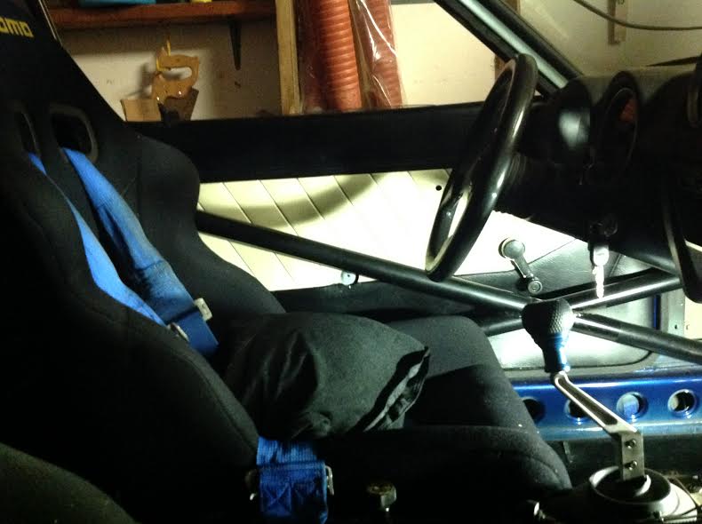
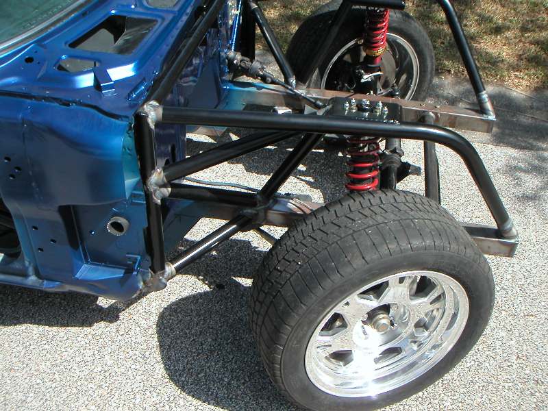
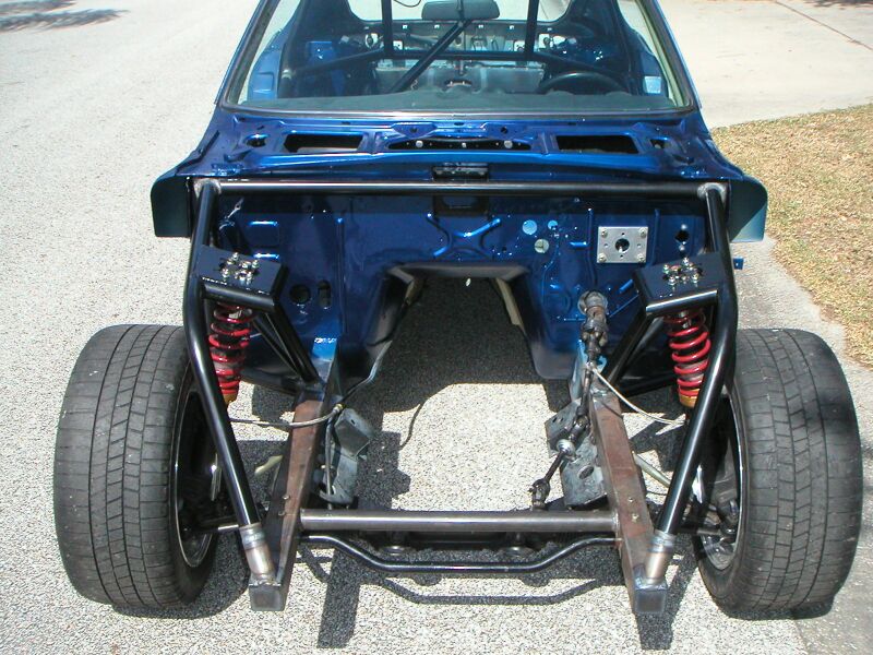
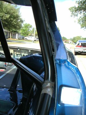
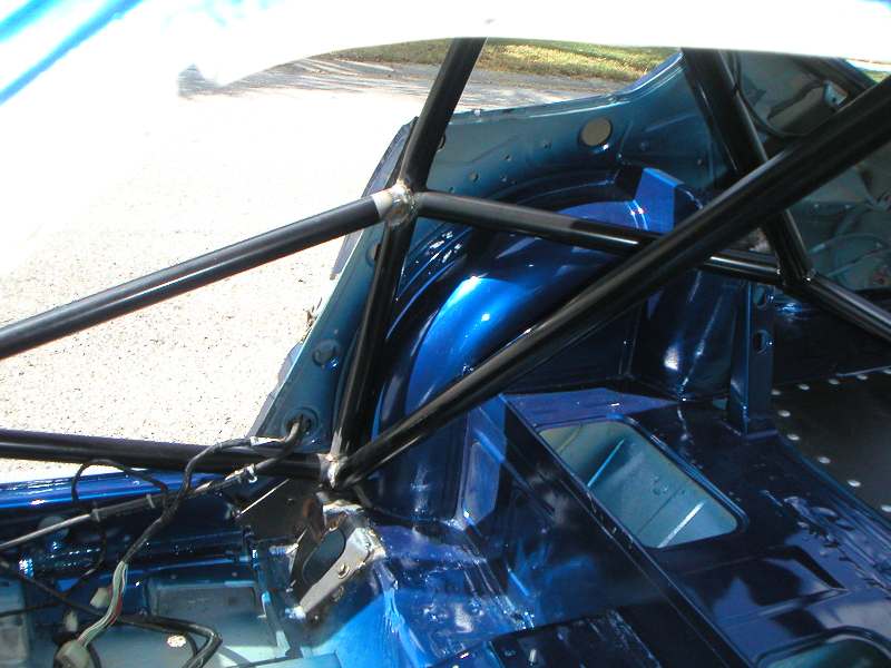
Here you go. I'm sorry there so dark, but I stink with a camera and the car is dirty from sitting these past two years. The second picture shows where the door bars penetrate the firewall to attach to the front. You could probably weld a plate in that corner to attach the door bars to if you didn't want to penetrate the firewall or if you don't want a front hoop.
-
Door bars that miss the window crank and door handle
74_5.0L_Z replied to RebekahsZ's topic in Fabrication / Welding
Here are some pictures from my chassis construction in 2003: The chassis is very stiff. I can jack up the car under the front sway bar attach point and get three of the four tires off the ground and still open and close the doors. The X across the doors is low enough that I can roll the windows down (the factory crank just rubs the bar as it passes). I did have to delete the 260Z armrest though.
-
Let's see some pictures of your ducting (both the inlet and outlet sides). I'm in the process of upgrading my font brakes (again). I've been running the Stage II brakes that Mike Gibson used to sell (11.5 x 0.81 rotor, Outlaw 2800 calipers), but now I want to change from running autocross to running track day events. So, I am upgrading to 11.5 x 1.25 directional vane rotors and adding cooling ducts.
-
I haven't used the Tokicos, but if they are gas pressurized like the old KYBs then they provide a significant force to extend the strut. Konis are not gas charged and provide no force unless the shaft is in motion. Preloading the spring will restore the ride height. I'm guessing that the rear of your car has about 650 lbs of sprung weight on each of the rear tires. So, if you install the springs without a preload the spring will compress about 2.9 inches. If you preload the spring by 1 inch then you will only compress the spring an additional 1.9 inches when you put the car on the ground and you will have that much rebound travel available Definitely get some thrust bearings to put between the spring and lower perch. I used to preload my old 250 lb springs. Before installing the thrust bearing, it was a herculean task with all of the weight off the tire. After installing the thrust bearings, I can adjust the ride height by hand while the car is on the ground. I got my thrust bearings from Speedway Motors. I was going to paste the URL, but the editor is not allowing copy/paste.
-
How much did you shorten the rear strut housing? You aren't at the limit of your strut travel (in rebound), are you? What is your spring rate and free length? If you do not have variable rate springs then your spring rate should be almost constant over the usable range of spring travel.
-
Torsional Rigidity Testing, 280Z
74_5.0L_Z replied to Chris Duncan's topic in Brakes, Wheels, Suspension and Chassis
Great stuff. However, we need pictures. I'd be willing to bet that most of the flex is happening ahead of the firewall. It would be great if you could get intermediate measurements at the front of the rocker panels. Keep up the good work. -
In Motion
-
4.6L Ford DOHC modular motor in my 240z
74_5.0L_Z replied to notheredave's topic in Ford V8Z Tech Board
Offsetting the engine toward the passenger side (right) is desirable to help balance the car left to right, to reduce driveshaft angle, and to get better clearance between the exhaust and the steering shaft. -
Blue Streak used to make high quality caps and rotors with brass contacts. I haven't bought any in a while. Hopefully they are still available and still of high quality.
-
I have way too much time in the headers. There are a few reason that it took so long. First, this was the first time I have made a set of headers. Second, stainless steel is expensive, and I wanted to get every cut perfect the first time. Lastly and most importantly, I was trying to finish my Masters Degree in Mechanical Engineering. So, time to work on the car was in short supply. The program that I wrote to calculate the bends actually began as a project for my Robotics class. I convinced the professor that the procedure to calculate the bends for a header was the same as that required to solve the kinematics of a robot arm with seven degrees of freedom (which it is). So, I spent a semester doing the math and writing the code to figure the header tube paths. I finished that class in 2011, but had several classes to finish for my degree so the headers went on hold while I collected parts and finished school. I finished my degree in April 2013 and finished the headers in August.
-
Cross Member Mounting Points
74_5.0L_Z replied to TieFighter88's topic in Brakes, Wheels, Suspension and Chassis
OK, I went back and tried to reconstruct what the error was with the 260Z FSM frame drawing, and I believe that I have found the error. I am posting the 260Z FSM drawing below so that I can point out the error. Frame.bmp The dimension between the TC mount and Point B is too short on the 260Z drawing. The listed value is 11.3 inches. If you look at the frame drawing posted by NewZed, that drawing shows the dimension as 12.88. That number is correct. Unfortunately, that dimension is to the engine mount on the crossmember. You can however measure the crossmember and calculate the additional distance you will need to the frame mounting holes. I hope this helps. -
Cross Member Mounting Points
74_5.0L_Z replied to TieFighter88's topic in Brakes, Wheels, Suspension and Chassis
I think the sway bar mounting holes would be the easiest and most reliable reference point. When I made my frame rails, I used the dimension of the sway bar mounting holes that were published in the FSM and had no problem. I did have issues with the published fore/aft position of the TC mount and the position of "Point B."