74_5.0L_Z
-
Posts
1194 -
Joined
-
Last visited
-
Days Won
30
Content Type
Profiles
Forums
Blogs
Events
Gallery
Downloads
Store
Everything posted by 74_5.0L_Z
-
This is the start of an analysis of the front suspension on my car. It has been modified several times, so most of the dimension are different than those of a stock S30. However, as part of this discussion I want to establish the geometry of the factory suspension so that we can compare various modifications and determine whether an improvement exists. During this discussion, I plan to present the geometry of my suspension and discuss how I arrived at those published dimensions. I also plan to discuss the mathematical model of the suspension, and finally to make the model available to those who need it. All I ask is that people refrain from posting until I have finished the initial part of the discussion. I will post several installments before I open the floor for discussion. Until that time, feel free to PM me with questions / comments.
-

Relocating LCA inner pivot point
74_5.0L_Z replied to socorob's topic in Brakes, Wheels, Suspension and Chassis
Actually, I have been doing a little deeper digging into suspension geometry lately and have discovered that I was not completely correct in some things. To explore the suspension geometry questions that I have had and that have arisen here lately, I created an accurate 3D kinematic model of my car's front suspension (in Pro/Engineer) which I could move and measure things like camber, caster, toe. The model was great, but making geometry changes was time consuming. So, when I was satisfied that I had an accurate model, I wrote a program using Visual Basic within Excel that given the same input as the Pro/engineer model gave the same output (camber, caster, toe). The nice thing about the program as opposed to the model is that I can change the geometry very quickly and see the results. The most difficult part was not making the Pro/engineer model nor was it writing the program, but was getting accurate dimensions of all the necessary components that make up the suspension. To model the kinematics accurately, you need to know the center of the attach points of the LCA, T/C rod, strut top, and inner tie rod relative to the chassis. You also need accurate geometry for the LCA assembly (which consists of the LCA, TC rod and ball joint), accurate geometry for the strut assembly (which includes the steering arm, spindle, strut insert, and spring), and accurate geometry for the rack and pinion. I have spent considerable time lately doing my best to quantify all of this, and I have been trying to find the time to post the measured geometry and the derivation of the model. I have spent hours cutting apart ball joints and disassembling steering racks and measuring all sorts of parts. I also plan to freely distribute the Excel Program to those who want it. Within the next couple of days I will begin a thread with my results. What I will ask in return is that those who have better measurements to provide them. -
Yeah, If mine was a street driven car, the fuel cell would not be fun.
-
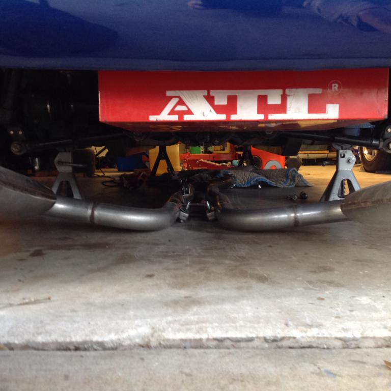
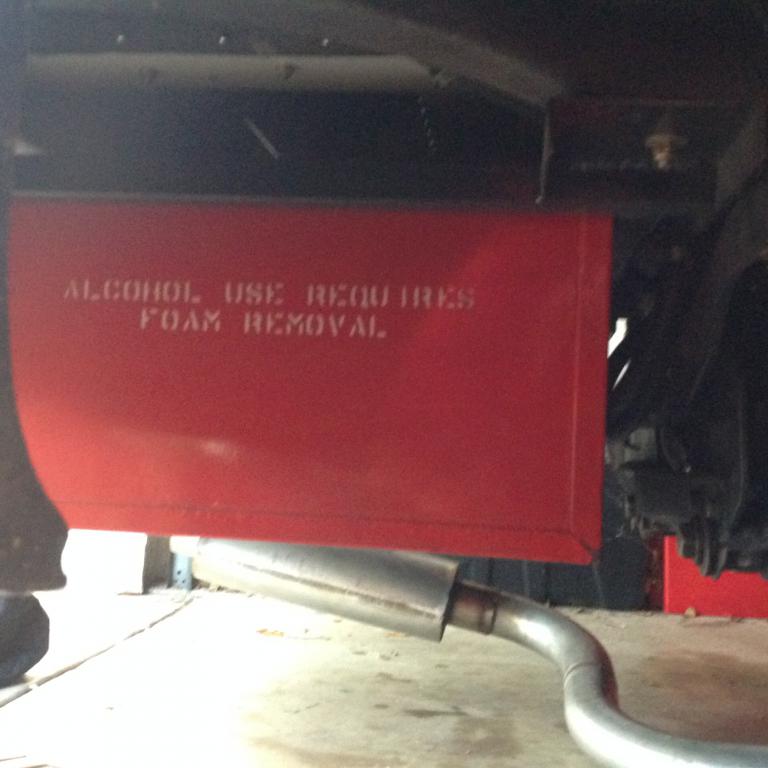
The type of fuel cell that you removed are terrible for fuel delivery. What you have created should work much better, but you could have achieved similar results with off the shelf parts. A real fuel cell (ATL or Fuel Safe) can provide consistent fuel pressure under all conditions even when the fuel level gets really low. I have an ATL SP112 cell with the ATL Black Box fuel pump and sump installed. The cell is 12 gallons and is mounted below the rear deck. The only real downside is that without a fuel sender, you do not know when you are low on fuel. I ran an event last weekend and made five full autocross runs with out starvation. Today I started the car in the garage and ran out of gas at idle. The only use of gas from the last run until today was loading and unloading from the trailer.

-
27/10/15 Hoosiers
74_5.0L_Z replied to mr_han_solo's topic in Brakes, Wheels, Suspension and Chassis
Those will be way too tall. Look at the Hoosier 23.0x9.5-15 or the Avon 23.0x10.5-15. About the tallest tire you can hope to fit on a non-lower 240Z is about 24.5 to 25 inches tall. -
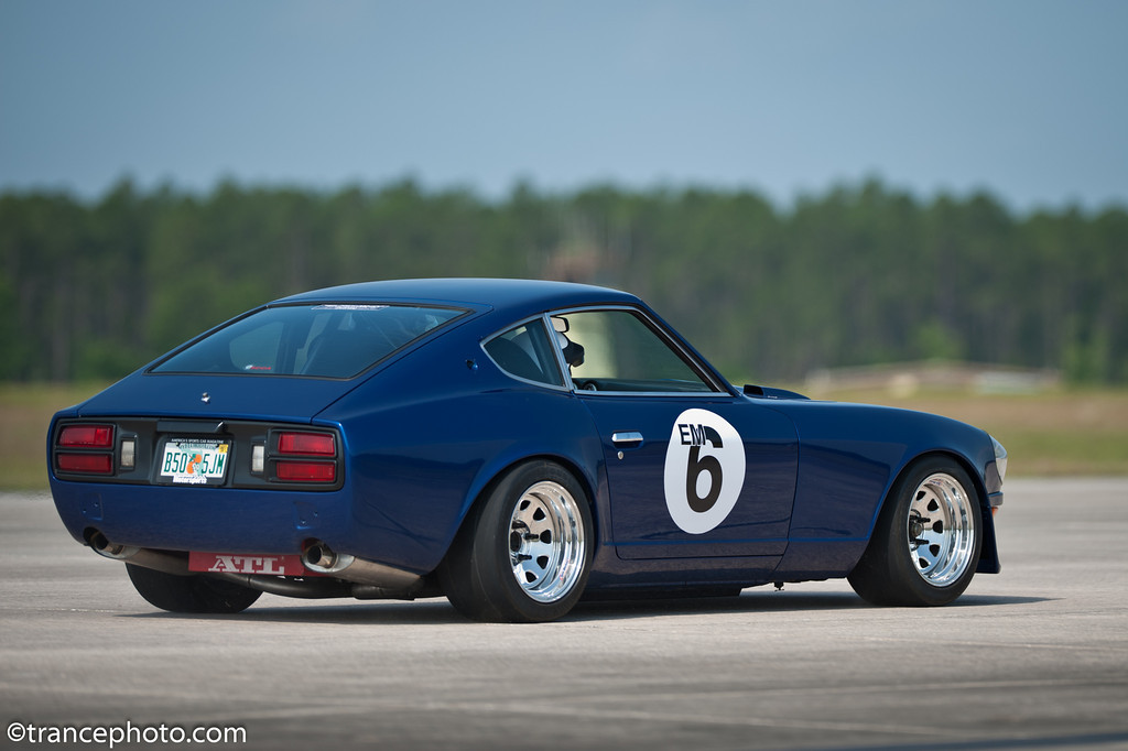
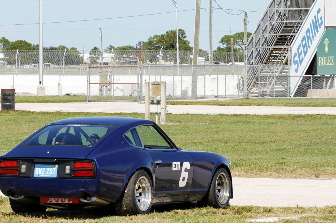
I haven't shown my rear end in a while, so here you go:
-
Wilwood Rotor Hat Now Offered
74_5.0L_Z replied to JustinOlson's topic in Brakes, Wheels, Suspension and Chassis
What size wheels do you need to be able to run those? -
Techno Toy Tuning - GTX2 Control arm and T/C Rods
74_5.0L_Z replied to ktm's topic in Brakes, Wheels, Suspension and Chassis
Cool. I didn't have dial indicators laying around, and I stumbled upon my bump steer set-up on ebay for $75.00. It is essentially two dial indicators, an adjustable base, and a graduated plate that mounts on the hub. -
Techno Toy Tuning - GTX2 Control arm and T/C Rods
74_5.0L_Z replied to ktm's topic in Brakes, Wheels, Suspension and Chassis
I am not sure how you would measure bump steer with just two dial indicators. What are they attached to for a stable reference, and how do you track wheel height displacement from nominal ride height? -
Techno Toy Tuning - GTX2 Control arm and T/C Rods
74_5.0L_Z replied to ktm's topic in Brakes, Wheels, Suspension and Chassis
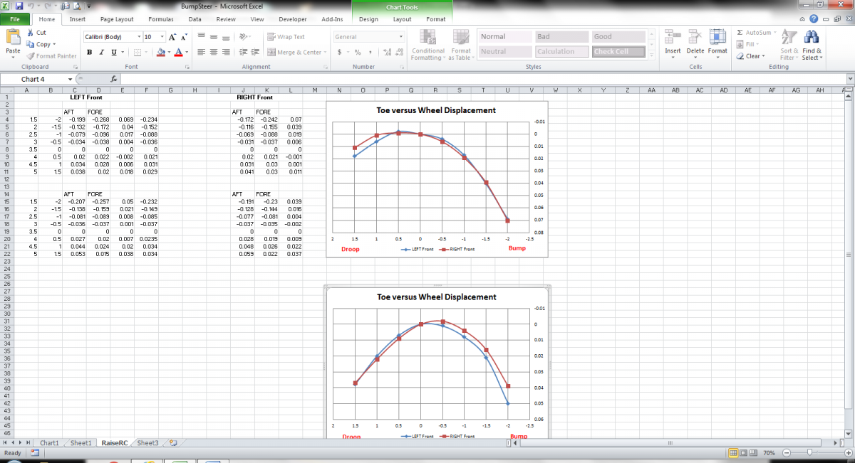
I have the InterComp Bump Steer Gage. I had to buy the four hole plate separately. When you bump steer the car, you need to do a few things to get accurate repeatable results. 1. Get the car on a nice level surface. 2. Center the steering. For this I have made two equal length (2.39") spacers that fit over the rack shaft under the boots that force the rack to its center position. 3. Find ride height on the strut shaft. For this I push the bump stop against the strut housing, lower the car, roll it back and forth, and then raise the car and measure the displacement of the bump stop. 4. Remove the springs and disconnect the sway bay. 5. Follow the instructions in the bump steer gage. Take measurements at 1/2" increments of bump and droop starting from ride height. You want to perform the bump steer measurement on both sides of the car. If the measurements from the two sides are significantly different, then the cross member may be shifted left or right, or the rack may not be square with the car. Attached below are two different rounds of bump steer measurement for my car. The top set was a baseline after I raised by LCA attach points 1/2". For that initial measurement, I used a stack of spacers to raise the rack .39 inches. From the curves, I had not raised the rack enough because bump was causing toe in. So, I made thicker spacers that raised the rack an additional .050". The second set of data shows that I shifted the bump steer curve slightly to the right and up. So, for at least the first 1/2" of bump, the tires bump out. My car has 500 lbf/in front springs, so I do not expect to get very much deflection over typical road bumps. If I raised the rack further, I would shift the curve farther to the right and farther up. As an aside, I am not really happy with these results. My next action will be to verify that a shorter rack will help the bump steer. My calculations indicate that a rack about 2.25" shorter center to center will virtually eliminate bump steer. To test this I am going to steer the current rack 1.125 inches and lock it in place. Then I will make a longer tie rod assembly to return the toe to its original setting (on one side). Then I will repeat the measurements above to verify that the shorter rack will fix the bump steer. Figure 10 of the following link explains how to interpret bump steer curves. http://www.woodwardsteering.com/PDF/tech%20section%20guide.pdf
-
Techno Toy Tuning - GTX2 Control arm and T/C Rods
74_5.0L_Z replied to ktm's topic in Brakes, Wheels, Suspension and Chassis
Everyone with an S30 has bumpsteer. Some bump understeer is good, but bump oversteer can be very bad. Some people notice bump understeer more than others. Everyone will notice bump oversteer because it makes the car difficult or even dangerous to drive. From the factory, the S30 has bump understeer. The front wheels toe out during bump and toe in during droop. This is desirable for a street car because it is stable on the highway. The factory bump steer is desirable because the following happens when you hit a bump with the factory bump understeer: Tire hits bump, suspension on that side compresses, tire toes out steering toward side which hits bump, car leans away from side which hits bump causing suspension to droop and toe to return toward original heading. Depending on severity of bump, the car may overshoot the original heading, but the steering will want to return to center. Now, lets say that you have lowered the car, raised the LCA attach points, added roll center spacers, and added caster without changing the rack height. It is highly likely that you will end up with bump oversteer. Bump oversteer happens when the tires toe in during bump and toe out during droop. This is a highly undesirable condition because of the following: Tire hits bump, suspension on that side compresses, tire toes in steering away from side which hits bump, car leans toward side which hits bump causing suspension to compress further and toe in further. This condition requires the driver to compensate by steering the wheel to keep the car pointed straight. Unfortunately, there is a critical speed above which the driver cannot react fast enough to correct. Bump oversteer is VERY bad for cars that are driven at high speed. For a race car, bump steer should be minimized (It is impossible to completely eliminate). The bump steer that can't be eliminated should be in the form of bump understeer. -
For me the S30 is just a blank slate for whatever I want to try. The only impediments to my imagination are time and money.
-
I don't want to redo the bodywork to fit taller tires.
-
I have seriously been considering some sort of SLA front suspension. The C6 is a logical choice for a donor. One of the things that concerns me about the C6 set-up will be the necessity of using 18 inch wheels. I would love to be able to use 15 or 16 inch wheels with whatever SLA set-up that I go with.
-
Techno Toy Tuning - GTX2 Control arm and T/C Rods
74_5.0L_Z replied to ktm's topic in Brakes, Wheels, Suspension and Chassis
Swap the fully threaded bolt for the appropriate shoulder bolt and you're in business. I like the idea of an adjustable mono-ball in place of the lower ball joint. Unfortunately, I'm not sure that I could package those inside my 15 x 10 front wheels. -
Modifyed Miata power steering rack for 240Z
74_5.0L_Z replied to BoonZ's topic in Brakes, Wheels, Suspension and Chassis
As far as the Woodward racks go, I think you can change the ratio just by getting a different pinion. I just went from the stock 260Z rack which had a gain of 1.59 in / rev to the stock 240Z rack which has 1.81 in / rev. The effort increase wasn't terrible, and the increased rack speed was noticible. Next I was planning to get the Woodward 2.09 in / rev (22 inches center to center) rack and install it without power steering. Then as funds permit I am going to add an electric power assist column. With a rack that is too long, all you can do is raise/ lower the rack or ends to get yourself on the right side of the bump steer curve. If you have bump steer, you want the front tires to toe out on bump and in on droop. Unfortunately, the slope of the bump steer curve is almost entirely dependent on the center to center length of the rack. -
Modifyed Miata power steering rack for 240Z
74_5.0L_Z replied to BoonZ's topic in Brakes, Wheels, Suspension and Chassis
3D Kinematics analysis of the S30 suspension shows that minimizing bump steer requires a rack with a center to center distance shorter that what came from the factory. Any rack longer than 24.25 inches center to center will make bump steer worse. For what I want from my car (autocross), minimizing bump steer is a priority. While power steering would be nice, bump steer and rack speed are more important to me. I have my eye on a custom Woodward steering rack that will be about 22 inches center to center. -
Modifyed Miata power steering rack for 240Z
74_5.0L_Z replied to BoonZ's topic in Brakes, Wheels, Suspension and Chassis
First, cool work on the rack. I hadn't considered modifying the length of an existing rack. I just measured up a 240Z rack for the purposes of modeling the front suspension kinematics. To do so, I disassembled a couple of spare racks that I have and measured their component parts using calipers and a tape measure. I even cut apart an inner tie rod to measure the ball diameter. Then adding up all of the measurements, I was able to determine that the center to center distance was between 24.2 and 24.3 inches. My measurements agree with yours but I can't specify the accuracy beyond one decimal point. It sounds like you have access to better measuring equipment than I do. Did you use a CMM for your measurements? Also, the stock rack has a total of 4.78" (2.390 each direction from center) of travel unless the factory limiters are removed. From my kinematic analysis of my front suspension, if I were to replace the stock rack with something different, I would buy or make one that was between 22 and 23 inches center to center. -
I have a friend who owns the company that makes the Brunton Stalkers. The Brunton M-Spec cars come with LS Engines and have side pipe exhaust. The sound of his cars is very nice, and well below the SCCA dB limit. He uses catalytic converters in line with the mufflers to keep the exhaust quiet. If you give him a call (Scott Minehart), he can tell you which mufflers and cats he uses. http://stalkercars.com/ Here is his car on track.
-
First impression of Formula Atlantic slicks
74_5.0L_Z replied to 74_5.0L_Z's topic in Brakes, Wheels, Suspension and Chassis
Cary, I did run limiters on the front for a while just to keep the springs from getting loose when I jacked it up. I've since raised the front just enough to no longer need them. Clark, I am not having either an understeer or oversteer problem. The car pretty much goes where I point it. It just takes more slip angle to make it change direction. I am still not used to the Bias ply slicks. The car always feels at the limit of traction (even when its not). I am slower on the bias ply than on the radials. I may get used to them and get faster after a bit more time, but I plan to go back to radials. So, I probably won't spend much effort trying to perfect this set-up until I am back on radials. -
First impression of Formula Atlantic slicks
74_5.0L_Z replied to 74_5.0L_Z's topic in Brakes, Wheels, Suspension and Chassis
The car could use more droop in the rear. Unfortunately, way back when I sectioned my rear struts, I shortened them too much. I have a couple of options to get some of that droop travel back. 1. Lower the rear. I can lower it about 1/2 inch before the spring loses all pre-load at full droop. Unfortunately, that gets me really close to rubbing the inside if the wheel well at full bump. 2. Add an aluminum spacer between the rear camber plate and strut tower to lower the camber plate mounting relative to the body. Then also perform option 1 but lower the spring farther. 3. Get some new rear strut housings and start over. -
First impression of Formula Atlantic slicks
74_5.0L_Z replied to 74_5.0L_Z's topic in Brakes, Wheels, Suspension and Chassis
I started with the tires in the 18 to 20 psi range and the tire temperatures seemed to indicate that was the correct pressure. Unfortunately, the car felt like it was falling over all the time and the tires were rolling under pretty badly. So, contrary to the tire temps, I started adding pressure until the car felt more stable. I've got the car down to 2580 full of fuel with me in it. I have 610 lbs on the right front and 638 lbs on the left front. -
First impression of Formula Atlantic slicks
74_5.0L_Z replied to 74_5.0L_Z's topic in Brakes, Wheels, Suspension and Chassis
Yes, I am experiencing the same problem that I spoke of earlier. This was a really tight course where you had to brake pretty hard and then turn pretty tight. I am trying to decide what I want to do to settle the car down. Currently, I have 500 lb/in front springs, 425 lb/in rear springs, 20mm front sway bar, no rear sway bar, and Koni 8610-1437race struts all around. The front suspension has the following static settings: camber: -1.8 caster: 6.3 toe: 1/8" out front roll center on the ground or maybe slightly below The rear suspension has the following settings: camber: -1.2 toe: 1/8" in The rear roll center is about 2.5 inches above ground. Tires: AVON 10.5/23.0-15 Cross Ply Slick (A11 compound) all around 22 psi rear / 27 psi front Wheels 15x10 with 5.25" back space mounted with no spacers. This gives me about 2 inches of scrub radius. I have no droop limiters on the car at the moment (except the struts themselves). The car really pitches around more on the bias ply tires than it did on the Hoosier A6 tires I was running. The tire itself seems to deform much more. When driving, I do not notice the tires lifting (front or rear). When these tires are done, I plan to go back to a radial. I am thinking about lowering the rear roll center, raising the front roll center, softening the rear springs, or adding a stiffer front sway bar.
-
If you don't want the 6061-T6 to crack when you bend it you have to ensure that the inside bend radius is at least 2.5 times the thickness of the sheet. So, if that is .125 thick sheet, you need a .375 radius. If you anneal the material in the region of the bend before you bend it then you can get away with a tighter bend (approximately 1.5 time the thickness).
-
I like how you blended in a rear spoiler to the quarter panels. What spoiler is that?