
bradyzq
-
Posts
285 -
Joined
-
Last visited
-
Days Won
2
Content Type
Profiles
Forums
Blogs
Events
Gallery
Downloads
Store
Everything posted by bradyzq
-
If the float bowls were emptying due to lack of fuel flow, the AFR wouldn't be able to go from 14.5:1 back to 10:1 in the span of about 250RPM at 5500RPM or so. That dyno sheet just looks wrong.....
-
I would question the dyno in this case. It is VERY odd that you have EXACTLY the same torque on the black run from 2750ish RPM to 5K RPM, flat as a table. It is also very odd that on a carbureted car with a distributor ignition that power peak is at EXACTLY the same RPM on all 3 runs, not even off by 1 RPM. And it is also extremely unusual that it appears the O2 wanders between only 2 readings (10:1 which is probably as rich as the dyno can read and 14.5ish:1). At an honest 10:1 AFR, your car would likely have killed the mosquito population for miles around and been unable to generate the good torque measured. I guess what I'm suggesting is not to put too much faith in that dyno sheet, and before you start changing needles and whatnot, make sure there really is a problem, and that it is as shown on the dyno sheet. Just my $0.02.
-
You'll want to check that the rotor is pointing to the correct post on the distributor cap once you've sync'ed the timing. It sounds like yours has been messed with enough that one should not assume it's pointing to the right post. Basically, with the engine manually at about 25deg BTDC, the middle of the rotor should be pointing at post number 1 on the cap, or, if you'd rather set the engine at TDC (easier to do), the #1 post should line up near the back (trailing) portion of the rotor. If you ensure this is the case, you will reduce your chances of arcing to the wrong cylinder.
-
What Derek said. Be careful with some "pro" MS builders.Not naming names because their builds still worked, but I've seen some (non-Z community) "pro" built MS boxes that are hideous in their execution. I've had great luck with DIYAutotune for MS stuff, if you're looking for somewhere that builds MS as well as supports it. The difference in price between unaseembled kits and assembled boxes is laughable. It's really not worth building it yourself unless you want to learn. It's a slippery slope when you start modifying and more boost is just a click or a few keystrokes away.... Enjoy!
-
What resistance to use with low impedance injectors?
bradyzq replied to Zmanco's topic in MegaSquirt
A typical high impedance injector will be 12-16 Ohms impedance. You can use that range for your calcs. -
All you need to use to calculate the right ratio is the RPM signal from the car and road speed from the dyno at any point in whatever gear you're running in. Your dyno sheet will still show MPH on the horizontal scale, but you will know exactly what RPM your engine is spinning. The dyno operator "should" know how to do this. Edit: I know this sounds very similar to z-ya's post above, but I'm trying to say that even if the the dyno can't be told what your overall gear ratio and wheel circumference are, the dyno operator himself should still be able to calculate this easily.
-
Water is not a fuel. But methanol and alcohol are. So, by itself, water shouldn't add power. It will cool the charge, and slow down the burn, thereby allowing higher pressure though. And the oxygen in the water is not particularily easy to access, so it won't add to the "air" either. BTW, I think the aircraft you mention could safely run higher boost while the water injection was active. That's how they got their power gains. As for methanol, it cools the charge but also is a fuel. When tuned for it, an engine needs to run leaner to compensate for the fuel component of the methanol. The cooling component acts as the water does. So, unless your engine is running too lean to begin with, I doubt you'll see any power gains simply by injecting water or methanol. You have to tune for it either way.
-
To clarify, a wobble extension is NOT a u-joint! It's an extension with a rounded off end that allows 15ish degrees of slack, like this: http://www.supermotors.net/getfile/463262/original/wobble.jpg The extensions themselves look like this: http://www.vapormatic.com/_assets/images/vla1269.jpg They can really help when trying to get around header primaries.
-
As are flex head Gear Wrenches and, of course, for the absolute win........ wobble extensions. With the extra few degrees a wobble will give you over a standard socket extension, you will be amazed what you can get a socket on.
-
You're using a Haltech _F_9, right? That's fuel-only, as you mentioned. What are you using to control ignition timing? IMO, that's primarily where your torque is hiding.
-
Hi All, I know this thread has been dormant for a long time, but what I have to add/ask seems topical, so here goes: Your flow analysis has been from the point of view of the charge air, since all else is external. The charge air sees a cross-sectional area in your case of 18W x 3.5D or 63sq. in.. This number is proportional to the flow rating of the intercooler, all else remaining equal. So, in theory, a 21W x 3D or a 25.2W x 2.5D intercooler core should flow the same as your 18W x 3.5D core. So having a shallower but wider core should not impede flow. But, would it not cool the charge air more effectively? The ambient air that is going through what it sees (in your case) as an 18W x 6H core has the biggest temperature delta (difference between charge and ambient air temps) as it just begins to pass through the 3.5D core. So, it stands to reason that it has the smallest delta temperature just as it exits the core. This means the ambient air cools less and less efficiently as it passes through the core. So, if the above is accurate, wouldn't a shallower core be more efficient than a deeper one? I realize you were just trying to salvage a crappy design, but the thread seems to have gone beyond that, even though it has barely touched upon the cooling abilities of different types/shapes of intercoolers (air-air in this case). If you're interested in doing the simulations, I'd be curious to see whether a 21W x 5.14H x 3D core or a 25.2W x 4.29H x 2.5D core would flow any differently than yours, all else being equal. These all have the same frontal area (108sq. in.) and same end tank x-sectional area (63sq. in.) Or try them with 6H, too? I have zero experience with the type of software you're using, but if you can introduce the cooling effect of the ambient air, it would be very interesting to see which version "wins."
-
I put on my Lonewolf intake, and 90mm TB
bradyzq replied to big-phil's topic in Turbo / Supercharger
It doesn't have to. You can plumb it the way Big-Phil has it. You send boost to the top of the WG to keep it closed, and let it vent to open it. And the lower port is always fed a boost signal. -
I put on my Lonewolf intake, and 90mm TB
bradyzq replied to big-phil's topic in Turbo / Supercharger
When did you do that? Maybe the diaphragm wasn't torn before, like when it would hold 9 psi to redline, but is now torn, or at least not sealed somehow, now that it can't hold 15 psi. Is it possible that the 15 lb spring is incorrect? As in it binds somewhere? Wastegate location is obviously fine if it could hold a low 9 psi. Buuuut, did I hear some doubt as to whether it really did hold 9 psi a couple of posts back? Can you try it again with your 9 lb spring? Let's weed out the bad or obsolete symptoms so we can move foreward. If it can't hold 9 psi, then that was a red herring and it led us astray. -
I put on my Lonewolf intake, and 90mm TB
bradyzq replied to big-phil's topic in Turbo / Supercharger
And, of course, quadruple check the vacuum/boost hose from the manifold to the bottom of the wastegate. -
I put on my Lonewolf intake, and 90mm TB
bradyzq replied to big-phil's topic in Turbo / Supercharger
Hmm, well that certainly is creep, and a lot of it! Have you checked to make sure your wastegate moves freely? I wonder if it is not opening all the way, and is therefore acting like a smaller wastegate. -
I put on my Lonewolf intake, and 90mm TB
bradyzq replied to big-phil's topic in Turbo / Supercharger
Can you also video the way the BC is plumbed, and scroll through the settings on the Profec while you're at it? -
I put on my Lonewolf intake, and 90mm TB
bradyzq replied to big-phil's topic in Turbo / Supercharger
But your wastegate CAN control the boost based on what you've told us. When the boost controller is not plumbed in and the only hose connected to the wastegate is a boost source to the bottom port of the wastegate, it gives you a smooth 9psi to 6500RPM, right? That proves the wastegate is doing its job. So that leaves only a few options: 1. The boost controller is plumbed incorrectly. 2. The boost controller is programmed incorrectly. 3. The boost controller is broken. So, based on that,how is the Profec plumbed in? How is it programmed? Duty cycle, gain, maximum boost allowed, duty cycle default when it overshoots max boost allowed? -
I put on my Lonewolf intake, and 90mm TB
bradyzq replied to big-phil's topic in Turbo / Supercharger
Have you tried increasing the gain on the Profec boost controller? It can smooth out the boost curve. The Profecs are usually pretty good. Job 1: get boost approximately where you want it after it's spooled. (adjust duty cycle) Job 2: make boost curve flat. (adjust gain) Job 3: get boost to correct level readjust duty cycle) -
280z Progress. Frame, Floors, Exhaust, Fuel Cell - Lots of Pics!
bradyzq replied to trwebb26's topic in Fabrication / Welding
Just a suggestion, but do your accel enrichment tuning last. Actually, turn them off, to zero, zip, nada, for now. If you nail your base VE tune with enrichment off, you'll find that you need way less accel enrichment later on to perfect your throttle response. BTDT x lots. Congrats! I'm curious about the weight of you car. How much (very worthwhile) weight have you added? -
Wheel Show! Post your pics of you wheels
bradyzq replied to k3werra's topic in Brakes, Wheels, Suspension and Chassis
15 x 7 0 offset Golden Wheels. They have hexagonal center bolt style centercaps, but I think they look better without them. -
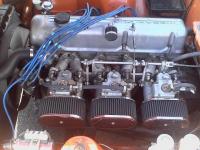
918 Orange 1972 Datsun 240Z, owned since 1990. 15x7 Golden Wheels, ZX 5 speed, 4.11 R180, 3x40DCOE18 Webers, 6-1 MSA headers, 2.5" exhaust.
-
-
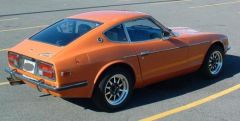
From the album: My 72 240Z
-
I put on my Lonewolf intake, and 90mm TB
bradyzq replied to big-phil's topic in Turbo / Supercharger
Hi Chris/All, I stand by my absolute vs. gauge pressure position on this one. To clarify a bit, consider your example at 15psi (1bar boost) instead of 22psi: According to your math (2.8L x 1.0 bar ( 15 psi) = 2.8L), a 2.8L boosting 1bar would ingest the same mass of air as a NA 2.8L, which is not the case. It should be equivalent to a 5.6L. Using absolute pressures solves this contradiction. Regarding the firing order (1-5-3-6-2-4), there are not 2 cylinders doing the same thing at the same time. Yes, for example, cylinders 1 and 6 will both move up and down together but they are not on the same stroke. For example, 1 will be on the intake stroke (down) while 6 will be on the power stroke (also down). Obviously only number 1 will have an intake valve open to admit air. In that respect, there is only 1 cylinder beginning its intake stroke at any given time. However, due to camshaft duration, that intake valve may be open for quite awhile, during which time, cylinder 5 and maybe even cylinder 3 may begin ingesting air. So, in THAT respect, there are effectively at least 2 cylinders somewhere in their intake strokes at any given time on our L6s. -
I put on my Lonewolf intake, and 90mm TB
bradyzq replied to big-phil's topic in Turbo / Supercharger
Me again. You're on the right track but a 2.8L at 22psi is running at 2.5bar if your NA Q45 example is at 1bar. You need to use absolute pressure here (1.5bar boost + 1bar atmospheric pressure). 1.5bar would be 7.4ish psi. So, assuming absolutely perfect compression of the air by the turbo and intercooler (no heat added and no pressure lost), that boosted 2.8 would ingest air like a 7L NA motor, not a 4.2L. -
I put on my Lonewolf intake, and 90mm TB
bradyzq replied to big-phil's topic in Turbo / Supercharger
Hmm, I don't agree. Why are you suggesting that the 90mm single TB feeds only 2 cylinders? It is a 6 cylinder engine. Yes, assuming 240degrees of duration on the intake lobes, since the cylinders are phased 120degrees apart, I suppose you could say that 2 cylinders are breathing in at any given moment. But that doesn't seem realistic to me. Especially as the revs rise and the time between strokes decreases. 6 45mm diameter circles have 50% more total area than 1 90mm diameter circle, not 50% less. One more question though: If the intake pipe is 90mm in diameter, and the intake runners are 45mm in diameter, assuming negligible flow disruption from the throttle plates themselves at WOT, does it really matter where and how many throttle plates there are at WOT?