-
Posts
150 -
Joined
-
Last visited
-
Days Won
2
Content Type
Profiles
Forums
Blogs
Events
Gallery
Downloads
Store
Everything posted by RB30X
-
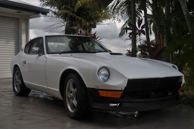
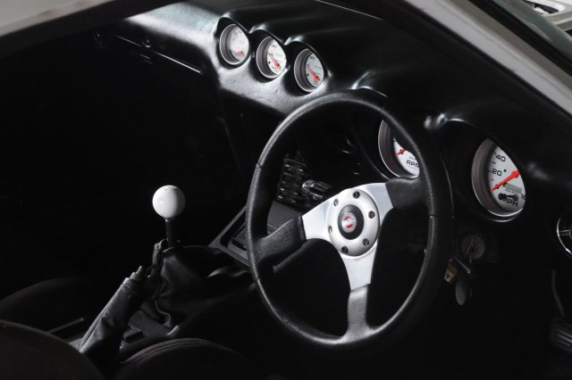
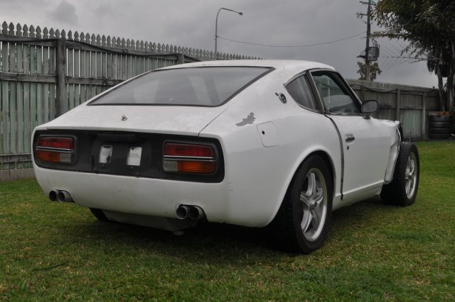
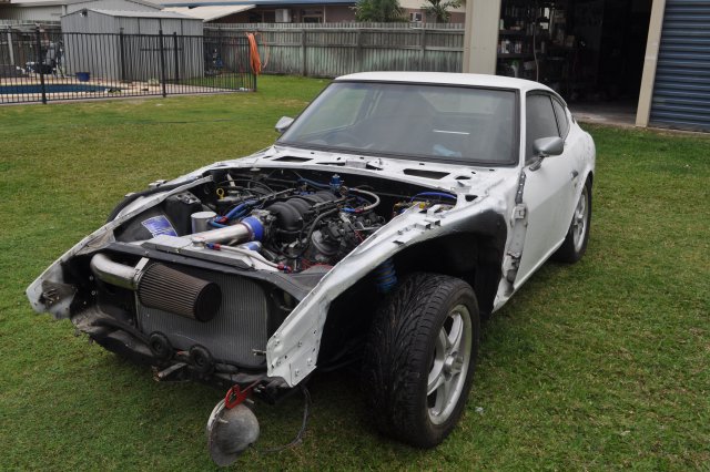
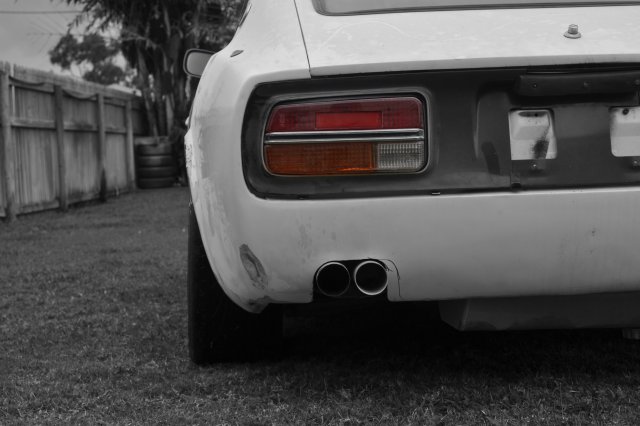
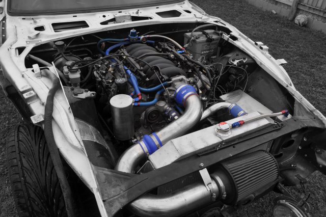
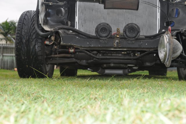
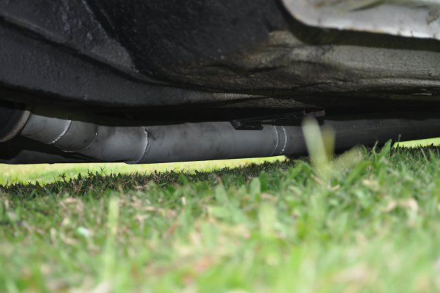
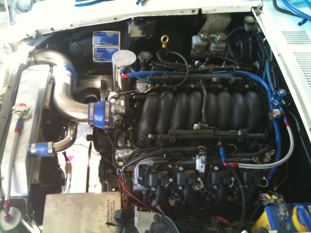
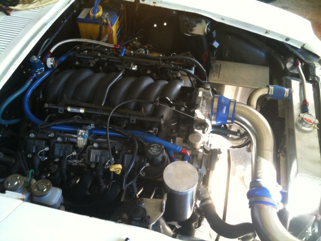
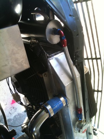
I thought I'd post some pics up here of my build. Its a 71' 240Z with an LS1 / T56 conversion, R200 diff, Z32 brakes and coil over suspension. Currently in the process of repainting it white. The last pics are with the coil overs dropped fairly low just to see what sort of clearance there'd be. Not much.
-
Hi mate, very good job with your car. I love the white paint job. I am currently painting mine exactly the same colour, same front spoiler and all. Do you have any other pics of it on a sunny day at all. Post up what ever you've got, I won't get sick of looking at them cheers
-

DIY Stage III Shift Kit Installation for S30 and S130 Jatco Autos
RB30X replied to RB30X's topic in Drivetrain
Yes auto's do limit the use of the vehicle in any racing forms except drag as you mentioned. There are the cruisers out there that have squeezed a little more horsepower from their L series and its the sloppy auto shifts letting them down. A shift kit would suit those people. There is a famous VL turbo track car in New Zealand with a Jatco auto. Smashing down gears coming up to corners in an auto does not offer the engine braking that a manual gearbox does though. -

DIY Stage III Shift Kit Installation for S30 and S130 Jatco Autos
RB30X posted a topic in Drivetrain
I have been contacted by a few people regarding a shift kit that I was involved in developing a few years ago. We actually developed this shift kit for the 4 speed Jatco 4N71B but recently adapted it to suit the S30 and S130 3 speed Jatco 3N71B. The kit is especially effective in turbo cars which soon destroy the standard auto after winding up the boost. The installation can be complex for some, but easy for others. It can be a great modification for those who have an auto S30 or S130 but don't want to go through the hassle or cost of converting to a manual. I have included some info below from my development (which may be different to others) so people can read up and understand the process involved, and find out what a shift kit does if they didn't already know. This shift kit was developed to reduce the sloppy, soft gear changes during acceleration in older cars with hydraulically controlled auto transmissions. This improves acceleration and reduces wear or damage caused to the transmission, espcially when the engine is producing more horsepower than standard. This kit allows safe operation of the standard auto with up to 14 psi boost pressure on turbo engines (calculated on the 4N71B 4 speed only). MY SHIFT KIT CONSISTS OF: 1 x DVD containing an electronic document with all the developed information including detailed photos and diagrams required for you to remove the valve body from your transmission and perform this shift kit modification yourself, as well as templates to show you which existing holes in your valve body require enlarging. 1 x Spring, to replace the existing pressure modifier spring inside your transmission’s valve body which will increase fluid pressure. All you need, is to have a small amount of mechanical know-how to perform this modification yourself. If you do not feel confident, you can always take the contents of this shift kit to an Auto Transmission service center and they can install it for you. An automatic transmission's main focus is smooth shifting between gears. To accomplish this it often goes into two gears at once while shifting up, which is known as a shift overlap. By installing a shift kit you are increasing the speed at which these gears are changed. It will also reduce wear because the transmission won't be taking as long to slip from one gear to the next, similar to riding or slipping the clutch in a manual gearbox. Increasing engine horsepower in automatic cars can also speed up the damage and wear caused inside the auto transmission because the automatic is trying to smooth out gear changes as it was designed, with only the factory levels of horsepower. This is especially the case with turbo engines where it is very easy to achieve up to 50% more horsepower with little modifications to the engine. HOW IT WORKS: An automatic transmission has bands and clutches that are actuated by hydraulic servos controlled by the valve body to change gears. It is this hydraulic control center or valve body that receives pressurised fluid from a main pump operated by the fluid coupling/torque converter. The pressure coming from the pump is increased by replacing a spring in the valve body so the regulated pressure is higher and as a result, pushes a network of spring-loaded valves, check balls and servo pistons much faster. The fluid ‘pressure’ is not only increased to speed up the gear change, but the fluid ‘volume’ as well. The valve body is contains a separator plate consisting of many holes which let fluid pass from one side of the valve body to the other. Enlarging particular holes allow a larger volume of the higher pressure fluid through. Turbo cars also make use of the existing vacuum line which runs to the auto transmission from the engine inlet manifold. This vacuum line initially uses the engine vacuum to control shift points. During acceleration when the engine is producing boost, this shift kit allows the positive pressure from the turbo in the intake manifold (boost) to increase the firmness of the gear changes as well. Installing a shift kit will not correct or eliminate symptoms of a previously faulty transmission. The auto gets signals to change gears from both vacuum from the engine inlet manifold and electronic signals from the accelerator pedal or throttle position sensor depending on year model. This shift kit will rely more heavily on the vacuum modulator on the side of your auto to control gear changes rather than electronic signals so if your vacuum modulator (small round thing your vacuum line hooks up to) is 40 years old it may require replacing to get the full benefits of this modification. Ok. So to perform this modification to your valve body you need to do the following. - Pick up a service kit which includes a new bottle of trans fluid, a new filter and pan gasket (usually pretty cheap). I also recommend running an external trans fluid cooler if you live where it gets hot as this will generally help your auto last longer regardless of your modifications. - Jack the car up, handbrake on and shifter in neutral. - Have a container ready to catch the fluid. Unfortunately there is no drain plug for this so it gets messy. Steps: 1. Undo the 10mm headed pan bolts starting from the lowest point of the pan. Oil will begin leaking from here first so keep drip tray handy. Take note of how easy the bolts come undone. This is how tight they should go back on. 2. As fluid draining slows down, support pan with one hand as you remove the last bolt. Lower pan away. *Note: How does your trans fluid look? Are there bits and pieces of fibrous material floating around in it, or is it dark in colour indicating high metal content? Does it smell burnt? These can be signs of how healthy your auto may be. 3. You should be able to see your valve body. 4. Take note of how the gear selector linkage is sitting in the rod on the RH of the valve body (red arrow in pic below). 5. Also take note of how the pins/rods from the solenoids on the LH side sit inside the valve body (yellow arrows in pic above). Note: depending on your auto you may have two electrical terminals to disconnect from the valve body as well. 6. Remove the following 10mm headed bolts (yellow arrows below) and providing you’ve left your trans in Neutral, you should be able to drop the drivers side down and slide it off the pins on the LH side. The vacuum rod can fall out, while the electrical solenoid rod will stay in there. Do not undo the nuts where the red arrows point to, you will undo these later. 7. Drain remaining fluid from valve body. *3N71B valve body pictured below. 8. On a clean surface, undo the 8mm headed bolts (and one 10mm) that hold the trans fluid filter to the valve body. Take note of the torque required to loosen. 9. Remove the remaining bolts, working from the outside towards the centre (this includes the second 10mm headed nut and bolt) As the very last bolt is loosened in the centre the valve body will begin separating. Hold it together with one hand as you remove the last bolt completely. With two hands holding it together like a burger, flip it over and lower it down on the surface where the filter was attached. 10. Remove the top half of the valve body ensuring the separator plate remains on top of the lower section. 11. Lift off the separator plate carefully and you will see a ball bearing sitting on a strong spring. There will also be one or two small cups sitting on very weak springs. It is important you remember where these go. 4N71B Valve bodies will have one black cup without a spring underneath. *3N71B shown here. 12. Remove the loose springs, cups and ball, and clean all the parts with petrol or Brakleen. There will be a lot of fine build-up in the small chambers and channels of the valve body. 13. Identify side plate A (as shown below) and carefully remove the three 8mm headed bolts. Take note of bolt torque. Valves inside are spring loaded so the plate will eject itself. *4N71B shown. *3N71B 14. Remove the pressure modifying valve and the spring. Replace the existing spring with the red ‘higher pressure’ spring (supplied with shift kit), reinsert valve. The stronger red spring will increase fluid pressure. 15. Compress the three valves against their springs so the plate can be reinstalled. This can be tricky. Try compressing the valve with the red spring first, then sliding the plate over it, then compressing the other two. *Red spring installed 16. With a clean separator plate, mark the holes to be drilled out using the template provided. (template included as part of shift kit, if I included the rest of the photos and diagrams, it wouldn't be fair so its words only from here) 17. Some holes just require enlarging to the diameter (mm) in the picture, others will need enlarging and elongating or extending. This can be done by drilling a second hole next to the existing hole, and using the drill or a dremil, port out the small gap between the holes. Ensure you do not go outside the stain on the separator plate that shows where the channels are. Drills holes out accurately and sand off burred edges of hole with emery tape. If this step is not followed, fluid may pass through where the separator plate does not seal. 18. Clean separator plate once again. 19. Reinstall springs and cups or balls in their original position. 20. Sit separator plate on top of lower half of valve body, ensuring cups and ball sit under original holes. 21. Rest top half of valve body on the separator plate, ensuring it stays straight. Compress slowly so cups and ball rest on their springs in the appropriate valley. 22. Flip valve body over as before, and with one hand keeping valve body compressed together, wind a couple of 8mm headed bolts in finger tight. 23. Install short 8mm headed bolts and the one 10mm to secure the valve body together finger tight at first so you ensure the valve body halves and separator plate all line up well, then tighten. Remember the initial torque required to loosen them. These are aluminum threads so we don’t want to strip them by over tightening. 24. Install new fluid filter with the remaining 8mm headed bolts and one 10mm headed bolt and nut. 25. Check all bolts have been tightened. 26. Slide valve body back up inside auto, ensuring solenoid pins line up again, as well as the gear selector rod. 27. Install bolts in correct order, note the different lengths. 28. Clean off old gasket from pan (cork gasket in this case) 29. Depending on what your replacement gasket is made of, apply gasket sealer etc and reinstall pan. 32. Add approx 3L of new trans fluid through your filler point. 28. Start the engine and with foot on the brake, test that the engine revs drop when auto is placed into Drive and Reverse indicating the auto is working as normal. 29. Drive car off car ramps or lower as required. 30. Trans fluid level should be checked again with the engine running at operating temp and the auto in Neutral or Park. Top up fluid as required by dip stick level. 31. Take car for drive and enjoy. Hopefully this little tutorial will help you guys understand a little bit more about how your auto works and what exactly a shift kit does. -
So you have a 4 speed manual in a 74'?
-
Can someone please sticky this?????? Any pics of a white S30 with goldly colored rota grids?
-
I seen a few people use this method as a sutle way of strengthening the chasis without going a full cage. I've got an LS1 in my 240z and I don't want it to snap in half the first time I drop the clutch at the strip with some sticky rubber under the rear.
-
What are these braces called and is there any info on what they are made from or where they should be installed? Thanks
-

Relocated ignition coils on LSx - any ideas?
RB30X replied to Boy from Oz's topic in Gen III & IV Chevy V8Z Tech Board
You get the dimensions of those brackets Peter and I'll fabricate them -
Ok. Maybe this has gone a little deep. I'd love a practical diffuser but how about just cosmetic. I've since found out it's about 150mm to wide any way so it would have tone shortened.
-

Running AN fittings & braided Stainless on Triples
RB30X replied to LowCarbZ's topic in Fuel Delivery
I did mine almost like how you describe you want to do yours. I am still very happy with the result and I haven't seen another set up I like better yet. A full thread of mine and more like it is below. http://forums.hybridz.org/uploads/monthly_03_2010/post-5891-12675448296219.jpg http://forums.hybridz.org/index.php/topic/89337-show-off-your-braided-fuel-lines-and-dash-fittings/page__p__848125__fromsearch__1#entry848125 -
That's correct, but its a start that looks good, and you could modify underneath to actually become practicle. As far as fabbing up a functional diffuser to fit a Z, if it was that easy, why don't we see them everywhere already. I mean good ones.
-
Has anyone here fitted a G8 or GXP rear diffuser on an S30?? I think it would look ok, especially if you have twin pipes out the back. They are pretty cheap to buy, I wonder how easy to fit? Someone with some photoshop skills should merge one onto a rear end to see what it woud look like.
-

Catch can location in an S30 LS1 engine bay (pics please)
RB30X replied to RB30X's topic in Gen III & IV Chevy V8Z Tech Board
-

Catch can location in an S30 LS1 engine bay (pics please)
RB30X replied to RB30X's topic in Gen III & IV Chevy V8Z Tech Board
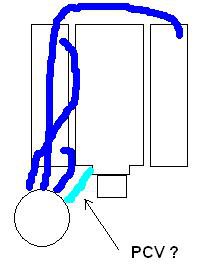
I've decided its going to go just in front of the RH bank. Our Australian LS1's have two breather hoses coming from the RH rocker cover and one big one from the LH. To keep it legal, these three breather hoses will go to the baffled catch can, and a single hose will return to the inlet manifold. Just before the current hose enters the inlet manifold, there is a PCV valve. Not sure how US ones are set up. Does this need to be there, and what difference would it make if it wasn't? Cheers Proposed set up: -
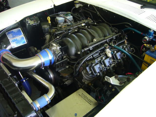
Just trying to sort out where the best place is to install an oil catch can / breather tank in my engine bay. It's an LS1 obviously. I'm currently making a radiator overflow tank that will go on the LH front wheel side of the radiator, and the engine pcm is there also so that space is taken up. Where have others placed such a set up in their engine bay?? I also noticed there isn't an 'S30 LS1 engine bay pics' thread, so maybe this could also be such as thread. Keen to see your pics.
-
Just updating some prices. I've found a new supplier of parts and can offer these fittings at a lower price. These fittings screw straight into your rocker cover: -8 $35 AUD = $30 US -10 $45 AUD = $38 US -12 $55 AUD = $46 US The -8 pieces are solid, straight from a CNC machine and the -10 and -12 are two stainless threads tig welded together.
-
That's what I'm trying to do mate. Use a fitting so the rocker cover doesn't have to be modified, the buyer doesn't have to do any welding and kept as low as possible. None of the fittings shown previously come anyway near the bonnet, and all have the same or larger breather size as the factory fitting. You seem to have gone down in size with your fitting ( -6 ??) which will increase the speed at which the oil vapour will travel which results in more oil carry over to the catch can. And as also mentioned above, probably doesn't look quite as good with the fitting so far down the factory breather, which will also put some pressure on the weld. Sure you saved some money by only buying a -6 weld on, but looking at that fine engine bay tells me you aren't worried about the cost.
-
If anyone one is interested in such a straight or elbow fitting such as above, let me know as I am about to place an order. Cheers
-
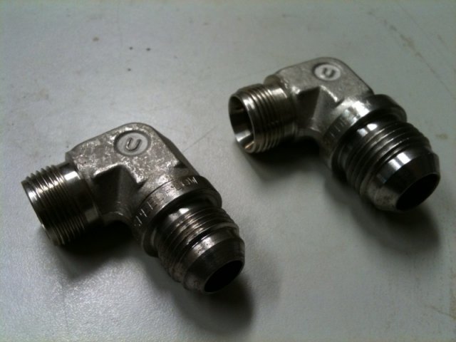
Here is another option. Elbows that screw straight into the standard rocker thread, then tig welded onto either -8 or -10 AN flare. This allows you to just buy a -8 or -10 anodised straight fitting, instead of an expensive bend. The inside diameter of the -8 'hybrid' fitting can be drilled out to the same ID of a -10 to acheive a better flow.
-
-
Here is the finished product. Quite straight foward really. Factory rocker cover thread into AN-8. I might see if -10 can be done too.
-
Just playing around on the lathe tonight. Trying to cut a UN thread on the dodgey lathe we have is going to be fun. I'm running with the -8 size as it's only slightly smaller in bore diameter than the standard fitting, plus -10 elbows look massive coming out of an L series rocker cover. The left hand side of the stainless fitting in the forground is the rocker cover thread, and the right side is obvioulsy trying to replicate the dash fitting without a thread cut yet.
-
Actually, I was just talking to one of my fitters and if we can tap our own NPT -10 threads we could do it much cheaper and eliminate welding all together. I'll do some investigationing.
-
Stainless in that size could be done for a little extra. I would get the stainless fitting with the rocker cover thread, get some weld-on stainless UN -10 nipples, then tig weld the two together. The tig weld would be on the rocker side of the fitting so you wouldn't see it anyway. It would be best to do a heap of them at a time to keep costs down. I know alloy and steel weld-on nipples are about $15 AUD in -10 size, but stainless steel ones are $25 AUD so much more expensive. But thats the price you pay for a fitting of that quality that will never deteriorate. Rocker thread + $25 -10 weld on fitting + about 20mins labour per fitting. $50 AUD is $42 USD atm Maybe $50-55 USD for full stainless?? It would cost $5-10 to send them to you individually?? Unless you got a heap sent to one person to distribute them once over there. Oh, and I have removed two factory elbows from the rocker cover by inserting a socket extension or breaker bar inside the horizontal section of the factory fitting to get some torque and just unscrewed it. They didn't come out easy but the fittings are strong and torque is your friend.

