macambra
-
Posts
171 -
Joined
-
Last visited
Content Type
Profiles
Forums
Blogs
Events
Gallery
Downloads
Store
Everything posted by macambra
-
New MS2 install. Runs but poorly. Settings help please.
macambra replied to macambra's topic in MegaSquirt
They do now. It was changed a few years ago as a cost cutting measure. I used to work in the auto industry. Nissan still lists it separately. Well, they did when I was working there 10 years ago. The oil filter is listed differently also by Nissan, but you can use a WIX 51515 (standard Ford FL-1-A). Some books like Fram's list them as the same. -
New MS2 install. Runs but poorly. Settings help please.
macambra replied to macambra's topic in MegaSquirt
I got it running pretty well, now. I could use some pointers, though. I'm still new at this and learning. My Z runs and drives but I can feel that it's still held back by something, and I think I need to turn down the boost. I only logged for a around 15 seconds. My idle hunts around a bit, maybe due to the cam profile. For some reason I can't post the files. I'll PM you with them. -
New MS2 install. Runs but poorly. Settings help please.
macambra replied to macambra's topic in MegaSquirt
Installed the factory FPR and adjusted the timing. It runs pretty well. Just a couple of bugs to work out and I'll be driving it. -
Maybe something like this even...

-
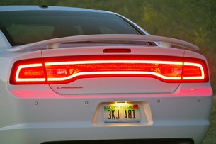
I have been thinking about getting some tinted glass cut to fit in the taillight recesses(flush with the body)and imitate the factory (late model taillight with black stripes) lighting with LEDs backing it. I was thinking it might be nice looking to have flush mounted taillights. I wouldn't be hard to manufacture, and the most costly part would be to get the tinted glass cut to fit. LEDs can be purchased inexpensively by the hundreds. You would need to mark out your pattern on a 1/16 inch thick black plastic sheet (in the shape of the taillight), drill holes for the LEDs, and wire up the LEDs with four parallel circuits(and a resistor for each leg)to divide the 14V. You will need four different circuits (brake, parking, turn, and reverse). You could use amber LEDs for turn signal and intermingle them with the reds to create a flip-flop look, or alternate straight lines with red and amber. The possibilities would be endless. It would just take some time to figure out what your pattern preference would look like. Hmm...maybe I'll start that project this summer...
-
New MS2 install. Runs but poorly. Settings help please.
macambra replied to macambra's topic in MegaSquirt
Replaced filter with a Z32 filter. It's not running lean, its running really rich. -
New MS2 install. Runs but poorly. Settings help please.
macambra replied to macambra's topic in MegaSquirt
I was thinking about my running issues last night(my brain won't shut off when I have a puzzle), and I think I'm going to remove the FPR and install the stock one back on. I think the fuel pulse from the factory pump might be causing issues. I had to remove the damper a while back, because it started leaking. The factory FPR seems a little more forgiving than the adjustable. I'll post my MSQ and log files next time I get a chance to run it. Thanks!! -
So, I finally managed to get my MS2 running again. I had it running a month ago and it ran pretty well. Then I had had some technical issues that I ended up finnally resolving. In the process of diagnosing the problems I replaced the factory injectors. Now I have it running and it runs like crap. I could use a little help with the settings. The list below has a running list of things I have done, some relevant some not. Please let me know what info or screen shots you would like. I followed the megamanual to perform the initial settings. Edit: Trigger wheel is set for 355 degrees per another user's posts. It seems to run at about 20 degrees BTDC at aprox. 1000 RPM (idle). my 280zxt PDF.pdf
-
Found the problem. It was a short between the leads of the new EV-1 pigtails. It looks like the shrink sleaving wore through. I ordered a set of 2 pin plugs to fix the problem permanently. Meanwhile, I managed to get it to run. Poorly, but it does run.
-
Update: Changed out Q1 last night(1 day shipping with USPS from Digikey--they must have a warehouse in Seattle). Works perfectly on the Stim again. Will try to get it back in the car and started tomorrow. Update edit: Tested wiring harness and definately have a short in the harness. Probably have a bad piece of shrink sleaving on one of the injector pigtails.
-
So, it's raining here in Washington State, and I don't feel like working outside. I decided instead to persue some testing on the MS2. I hooked up the JimStim and turned it on and lo-and-behold the Inj1 LED came on without having any RPM. I tested Q1 with my DMM and it is completely shorted. Off to order a couple of IRFIZ34N's... Thanks for the help guys!!!
-
I'll take #2, and #4. No, 86 didn't come with LSD in the US. 87 was the first year and only in the turbo. That's not to say that a PO may not have installed one- You'll never know untill you check it out. Factory Service Manual(FSM) check out xenonS130 website in the refference section. It's a free download.
-
As an electrician and part time electronics guy, let me tell you from experience-Spend the $65 and buy the DIY wiring harness. I built mine and I spent sooo much time building it and troubleshooting it, that it is not worth the effort. I built my relay board also, but once again-time vs money. Fortunately mine worked the first time and I didn't have to troubleshoot anything. A small detail I put into my relay box was an auxillary switch to bypass the ignition switch. I made a relay with some alligator clips and a radio shack horn button to make a remote start switch, and now I have complete control of the engine without climbing in-n-out of the car repeatedly.
-
Batch injection, running two banks-inj1,inj2-with 2 5amp fuses. I'll try the stim again, but last time I checked everything worked on my MS2. I think my next srep is to tear apart my harness for more testing.
-
So I'm back at it. Installed the 440cc injectors and my Pallnet fuel rail. Looks great. Replaced all the fuses, changed the injector perameters in tuner studio and tried to start. I managed to get it to fire and run on 3 cyl's. One set of injectors is still popping the fuse. I bypassed the fuse and gave it a straight shot and it popped the 20 amp fuse. At maximum the injectors should pull 2.5 amps (14.7/3= 4.7{following the formula for parallel resisors}then {E=IR (12=I*4.7)=(12/4.7=2.55319)}). Yes, I know it uses a PWM, so, it shouldn't draw anywhere near 5 amps, nor should it draw enough to pop a 20 amp fuse. Specs and tests: Full charge on battery-straight from charger to the car after 12+ hours charging. Tested wiring from injectors to relay and injectors to DB37-good continuity. Tested wiring insulation resistance- no shorts. High Z 440cc injectors- 14.1 ohms MS2 extra 12-1 CAS DIY disk. I check the MS2 on the JimStim before changing the injectors, and it seemed fine. Power for both injector sets comes from the same relay I suspected it's somewhere between the injectors and the MS2 but can't find it. I'm not quite sure where to look now.
-
If you can't get it figured out try this link. It's a PCB mount USB- DB9 replacement. I used it for my board and never had a communication issue at all, and the best part is that I don't have an adaptor sticking out. One tiny USB plug. Quick, simple, flawless. http://www.soselectronic.com/?str=998 Edit: I forgot to bring it up-The driver for this unit autoloads in Windows7. It was so easy, I didn't even need an easy button.
-
This guys flat tops look nice!!! http://www.youtube.com/watch?v=VgbQ33VJhIo http://www.youtube.com/watch?v=TR_5h-unBbE&feature=related
-
So, for those of you following this thread, We continued conversing via PM. He managed to resolve his issue by re-flashing.
-
Edit: No jumper. You are correct it does say to install it. It was written for the MS1 and some things need to be edited. I used the MS2 extra manual to assemble mine and there are alot of parts that don't need to be on the PCB. If I'm not mistaken you don't need any of the clock circuit stuff (MegaManual step 27+)since the clock is built into the MS2 DB. I never installed the crystal on my board. Take a look at the MS extra manual assembly guide. You might find that you want to assemble/change it per that manual, and then flash the MS2X 3.2.1 to your processor. You may or may not find it easier. Try not to get frustrated with the system- there's alot of info and alot of way to construct your MS2. The best way to do it is to follow EACH circuit to its ends and read, read , read. It's overwhelming for a while, until you have that "Aha!" moment. Edit#2: The clock circuit is completely bogus. You don't need to install it or uninstall it. It connects to nothing on the MS2DB. According to the schematic of the PCB and the DB, the clock circuit goes to pins 4 and 5 of U1 on the PCB. The DB has nothing connected on 4 and 5. It has no function. Sorry to alarm you for no reason.
-
Clock circuit? You didn't put the crystal on the PCB did you? You only need it on the PCB for MS1. The MS2 daughter board has a crystal on it already. I'm in Bremerton if you want to get together and hash out the problem. I'd hate to see you give up on the project when you're so close. PM about your decision either way.
-
Per MegaManual: 50. Next you need to make a decision. There are two input circuits for the tach signal: The Hall/optical/etc. circuit takes the square wave input from a Hall sensor, optical sensor, or points. It can also be used for triggering off the coil (but only if you are not controlling ignition timing). The VR circuit takes the AC signal from a variable reluctor sensor and converts it to a square wave for use by MegaSquirt. The Hall circuit can be built two ways - for a digital signal such as a Hall sensor or optical sensor (step 50.a.) or for a coil negative terminal (50.b.). these are the same circuit, but different components. The VR circuit is install in step 51, if desired. Did you install the right componants?
-
Yes.That's why there's a pull up resistor from a 12V source. Like Kaito said: build the circuit for VR and all should be fine.
-
Get away with what? You should read the Megamanual about applying the VR style dizzy, or the MSExtra manual, if that's what you're reffering to. Or adapt a 300zx (Z31) dizzy to your car. All of the Z31s have the CAS optical dizzy. Might be easier and better in the long run. If you're talking about the FIdle trick, It will work with anything, it's an output setting.
-
Did you change which point the tach signal goes to on the PCB in tuner studio? For my setup L28ET with CAS dizzy I had to change it to JS10 I think. It's in the "How to megasquirt 280ZXT" on DIYAutotune's website. http://www.diyautotune.com/tech_articles/how_to_megasquirt_your_280zx_turbo.htm Edit: It might be helpful to you (if you don't use FIdle) to change the Tach output to FIdle. So, when you put the MS on the Stim, the FIdle LED will flash. Just a nice visual cue to give you a warm fuzzy.
-
Remove the manifolds and replace ALL of the studs(head and manifold). Grind the broken stud down close to the manifold, use a sharp punch to make a dimple in the center of what's left of the stud, use a 1/8 drill bit to drill the center out of the stud, then use the next larger drill bit, and then use an easy-out. If the easy-out doesn't work then use a dremmel to cut into one side of the stud to oblong the hole toward the threads to break the tension then use the easy-out. Or if you drilled the hole slightly off center to begin with use the dremmel method. I had the same problem with my turbo manifold- the dremmel method works. Oh-Don't forget the Kroil. Once you drill the hole fill it with Kroil. If you nick the threads it's not a problem. Run a tap down the hole. as long as you have more than half of the threads it will hold just fine. There is not enough torque there to make a difference, just alot of expansion. In the end you will be glad that all of the studs are replaced. the aft exhaust studs are prone to breakage after long periods of time (30+ years). Every Z car that I have ever owned(5 early S30,2 S130) had the same problem with head and manifold studs.