
Michael
-
Posts
828 -
Joined
-
Last visited
-
Days Won
9
Content Type
Profiles
Forums
Blogs
Events
Gallery
Downloads
Store
Everything posted by Michael
-
I've found that if you have significant hot rodding and mechanical experience, you develop a "nose" for low-tech, low-cost, yet perfectly sound solutions. But lacking that experience, one tends to saddle himself with unnecessarily "high tech" methods. Part of the learning curve, I suppose. For a 300hp V8 Z, my opinion is that the only unavoidable "high tech" part is the manual transmission. Detriot products rarely came with stick shifts - especially the high-powered ones. The typical stick shift transmission (T5) is generally regarded as being too weak for 300 hp. The Muncie 4-speed is OEM, but those are rare, expensive, have an awful selection of gear ratios, and are probably notchy as well. Aftermarket choices - T56, Tremec, and Richmond gear - all involve some custom work, especially with clutch and bellhousing. Perhaps 300 hp is a "borderline case"; it might be better to go with, say, 250 hp (use a T5, don't worry about roll cages or subframe connectors, etc.), or go "all the way" for a 400+ hp street/strip car. Sometimes I really envy the muscle car guys. Their projects seem to be so off-the-shelf, so simple to assemble. The aftermarket industry offers trememdous support for these vehicles. But a V8 Datsun has a way of snowballing into an exotic custom creation, even with the most sober and "basic" intentions. It's a great engineering adventure, and surely gives the owner/builded more satisfaction than hopping up his Camaro or Chevelle, but sometimes "low tech" ends up feeling like a too-good-to-be-true fantasy.
-
The solid vs. independent rear comes up form time to time, but I've yet to see a rigorous explanation for the situations in which one is superior to another, except of course the superiority of IRS for rough pavement. Herb Adams' book is interesting reading, but too is vague about the issue. In the solid rear axle setup, the orientation of the rear tires relative to one another does not change, apart from minor motions caused by deflections of the axle under load. In the IRS, the camber of the left and right wheels changes relative to one another, depending on the vertical deflection of the suspension. That part is, of course, obvious. But what's far from obvious is whether this relative camber change necessarily reduces traction on launch (for example). There is little doubt that a Ford 9" solid rear axle is stronger than a Datsun IRS with R200. What I'm wondering about is whether in a hypothetical apples-to-apples comparison, the solid axle setup has better traction. IF the two systems, when "properly set up", have comparable performance - that is, if the difference is only a matter of strength and durability - I would prefer to stick with the IRS. But if I find that I just can't put the power to the pavement, even with huge slicks, then I would persuade myself to spend the >$5000 on a custom solid rear end and 4-link.
-
Very clever! where does one get ahold of liquid nitrogen - or for that matter, just dry ice???? I just completed my car's de-tarring. Took about a week with a chisel and hammer to do the whole floor and hatch area, and there's still a "residue" left. Lots of cursing and dozens of cuts on my hands. Pete's right - there is rust hiding underneath that tar, even if the top surface looks dry and pristine. The worst places are where the sheet metal panels join, and are covered by rubbery white glue. Rust wants to form at those joints. Of course, the metal is unpainted in those areas!
-
WANTED!!! Scan of structural diagram for 77 280Z
Michael replied to a topic in Brakes, Wheels, Suspension and Chassis
Fascinating drawing! Yet more evidence that this is by far the most useful automotive forum on the internet! One thing to notice is how the 280's frame rails continue for a long distance underneath the floor pan, but terminate ~6" ahead of where the rear subframe begins. A lot of unibody cars are apparently designed that way - almost full length frame rails, but not quite. I heard that the reason for this seemingly idiotic design flaw was NVH; splitting the frame like that is a deliberate compromise of rigidity to reduce vibration and harshness. On my '78 280, the "stock" subframes were retained, but were extended to the rear clip, and now terminate at the hard points where the rear sway bar used to mount. It's also interesting how the rocker boxes - probably the strongest beams in the whole car - just appear to float in space, supporting neither the engine nor the suspension loads directly. The roll cage design that I was talking about in an earlier thread was an attempt to tie into these rocker boxes. -
Well, there's more than one way to skin a cat, of course. But, I just wanted to make a couple more comments about the method that I attempted to describe.... With the roll bar "opened up", it ends up outboard of the seat. In fact, the seat backs up all the way to the wheel well. I'm only 5'9", but the firewall (and pedals, and steering wheel, and everything else) in my car is 6.25" set back from stock. With the way I have the seat mounted now, my legs are too short to even reach the pedals. The top of the roll bar sits underneath the stock roof "bridge". It's right under where the dome light used to be. But, I have to admit that I'm not using a stock seat. I have a Kirkey aluminum "drag race" seat, which is thinner and narrower than the stock seat.
-
Owen, I don't have the S&W cage, but the main hoop of my cage is anchored the way I'm describing in the following paragraphs.... My advice is to weld a 6"x6"x3/16" (or similar size) steel plate right over the "box" where the seat belt retractor thingy used to sit, and where the end of your roll bar hoop currently sits. That distributes the roll cage loads over a broad surface, instead of introducing a stress concentration, as would happen if the roll bar ends were welded into the seat belt retractor box. Tie that piece of steel over to another piece of similar thickness, welded along the side of the rocker box. Then cut the roll bar ends, and butt weld them to the plate. If you have access to a means of bending tubing, I suggest that you "open up" the roll bar (that is, reduce the angles of the bends in the corners at the roof and the side windows), to get the bottom ends of the roll bar to sit further outboard - that is, closer to the rocker boxes. Then you can weld the ends of the roll bar into the "corner" of your 6"x6" plate and the rocker box, and leave more room to pull back the driver's seat. That also makes a natural hard point for welding in X-bars in the door openings, and for a bracket for the lap belt portion of the safety harness.
-
The "NMCA drag racing series" has recently been featuring turbocharged Chevy small blocks in its semi-pro classes. These are making well in excess of 1000 hp. The hot setup is twin-turbo, with a huge intercooler sitting in front of the radiator. These are $50,000+ engines. One guy is even running a turbo destroked big block. On first impression, there is something mutually exclusive about turbo and V8. The combo can work, but I don't think that there is enough of a customer base to justify significant involvement from the retail aftermarket. Evidently that's why the V8-type car magazines only talk about the super high-end when they mention turbo V8's. At how many psi does a stock Buick GN boost? I wonder what tinkering would be required with the SBC bottom end to survive with the same boost level....
-
Folks, This might not be entirely related, but I was just wondering what people considered to be a "tube frame". My idea of a tube framed car was one where every body panel just bolts to the tube superstructure. So, the floor boards, the firewall, the roof - everything - is just along for the ride, while the "tubes" take care of all the loads. So funny cars are "tube framed", but something like the GT-1 Porsches and Corvettes are not.... ....which probably means that a roll cage bolted to a ladder frame, with the stock body welded on top, is not a tube frame. Any opinions? As to the original posting in this thread, I would have thought that the strongest part of the stock Datsun body is the structure forward of the firewall. So this would be the last portion of the car that one would remove and replace with a custom piece. The spacing between the frame rails is wide enough to fit even a big block, though accommodating the exhaust does require some modification. The area where the tension/compression struts mount underneath the frame rails is a natural hard point, and a good place to weld supports for engine mounts. With some fabrication, it is fairly "simple" to splice the front end of one Datsun into the rest of the body of another. The front clip of my car was completely cut off (and then welded back together), to accommodate my firewall setback project.
-
weight distribution - some measurements...
Michael replied to Michael's topic in Brakes, Wheels, Suspension and Chassis
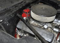
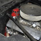
Folks, OK, here it is - pictures of my car: http://members.home.net/pparaska/MichaelOlsZ.htm A big huge thanks to Pete Paraska for hosting my "web page"! I apologize for the sloppy photography - hopefully I'll have better images soon. The last photo sort-of shows how the engine is installed, but the rear 1/3rd of the engine sits under the windshield valence panel, obscuring the view. If you look closely, you can see the Griffin radiator angled forward. With the hood closed, the air cleaner just barely sticks out. Big blocks are tall. I had to either put up with the air cleaner sticking out, or the oil sump hanging too far below the frame rails. Contrary to what the label beneath my user name says, I now live in Dayton, Ohio. Which means that racing season is drawing to a close. It won't be until next spring that I'll get a chance to run the numbers on the car at the track. But, it will take at least that long to fix the rod knock, figure out how to upgrade the stock half shafts, sort out the wiring (I threw away the 280Z electrical system and started from scratch), sand out the rust and get the car painted, etc., etc. Currently there is no room for the windshield wiper assembly, the dash won't fit because of lateral roll cage bar that's in the way, the window cranks and arm don't clear the X-bars in the door, and the fuel cell sits right behind the rear strut towers. But these are "minor problems", compared to what had to be taken care of us to get this far -
The best estimate that I have heard for fully dressed L28 (no transmission) is 425 lbs.
-
weight distribution - some measurements...
Michael replied to Michael's topic in Brakes, Wheels, Suspension and Chassis
Some more details... The battery is in the rear, next to where the fuel tank vapor canister normally sits. The radiator is a Griffin 28"x19" (frame rails notched to fit the wide radiator). Suspension is completely stock. The motor is all cast iron, except for block hugger headers and aluminum intake. For big blocks, aluminum heads are claimed to save 70 lbs. I looked at the GMPP aluminum heads - they are one of the options, along with Edelbrock and Brodix, among the oval port choices. Do any of the big block drivers have a particular recommendation? -
The transmission that I was talking about (Doug Nash 5-speed) was purchased used, with a claimed 20,000 miles on it. The application was in a V-12 Jaguar, and the seller claimed that he was selling it only because he upgraded to a six-speed Richmond (no overdrive in a Jaguar is even sillier than no overdrive in a Datsun). Anyway, what I bought almost certainly inferior to a brand new unit. But I only paid $750, with the shifter. The transmission also makes a dull "whirring" noise when going in reverse - and only in reverse.
-
My understanding of the flow measurement techniques is that cylinder head flow numbers are always obtained from tests on a flow bench, never on a running engine. On the flow bench, the head is subjected to a fixed pressure drop. Generally that number is 28†of water, which corresponds to approximately 1.0 psi. Each port is tested individually. The valve is held open at a set opening height, and flow volume measurements are taken for a sequence of opening heights. Generally, the intake manifold and engine block are missing; they are “modeled†by plastic pieces which attempt to approximate inlet and exit conditions at the cylinder head ports. And this is all done at steady state conditions and room temperature. So there is no combustion going on, no valve motion, no port-to-port crosstalk, etc. It seems to me that flow rate numbers are only useful as a relative comparison between different heads in the same catalog, and not as an accurate guide of what a particular head will flow in a particular engine. For instance, for my streetable big block, I can choose an “oval port†head that is rated to flow 140 cfm (intake) at 0.200†valve lift, 270 cfm at 0.500†lift, and 290 cfm at 0.800†lift, or rectangular port heads that flow 120 cfm at 0.200â€, 280 at 0.500â€, and 400 at 0.800â€. My cam tops out at 0.504†intake lift, so the rectangular port head’s high flow numbers at 0.800†are useless. But the oval port head’s better flow at low-lift will hopefully – hopefully! – increase low-end torque and throttle response. On the other hand, recent experience has shown that 450+ ft-lbs in a 2700 lb car and 3.27 first gear does not call for a lot of low-end torque. Probably the OEMs have the capability to measure flow in the ports while the engine is running; for example, by laser-doppler velocimetry. Otherwise they’d have a tough time designing such things as intakes with variable length runners. But I would be greatly surprised if any of the aftermarket manufacturers had comparable imformation. Making guesses is a big part of the hot rod hobby!
-
Well, amidst the chaos of the apparently failed rod bearing, I got a chance to weigh the "set-back rat" on a set of four digital scales. Here are the numbers (all are in lbs): with no occupants: left front: 718 right front: 690 left rear: 643 right rear: 674 total: 2725 with the driver: 777 680 727 723 That comes out to about 51% front/49% rear. I was hoping for something like 47/53. However, the car came out 100-200 lbs lighter than I expected. This is a '78 280Z with about 150 lbs of roll cage and other steel inforcements, aluminum (currently empty) fuel cell, 90% of the interior missing, no dash, no HVAC system, but all metal body panels installed, and technically in running condition. The most forward right-side spark plug is ~8" behind the wheel centerline. The conclusion is that 1) big blocks are really really heavy, and 2) decent weight distribution is still possible, but requires elaborate revisions to the stock vehicle.
-
a first drive - and spun rod bearings
Michael replied to Michael's topic in Gen I & II Chevy V8 Tech Board
whoops - the previous post got cut off. Anyway, after a few laps around the block, I noticed a loud and annoying knocking sound coming from the engine. It is proportionate to the rpm, but it is not constant. Rather, when the sound is loudest (at any given rpm), oil pressure appears to drop. Then the sound intensity ebbs, and oil pressure returns. While I have no tachometer (yet), I doubt that the engine ever saw above 3000 rpm. Trivial errors such as crossed plug wires and vibration of under-hood components were elliminated. Is this the tell-tale sound of a spun rod bearing? I'd hate to have to rebuild the engine before the car even makes its first pass down the drag strip. -
Yesterday I drove my '78 280z for the first time. It has a near-stock 454 big block engine and Doug Nash 5-speed transmission. With the stock tires, wheel spin is unavoidable in any gear. In traffic, the car is best driven by starting in 5th gear and never shifting. Maneuvering around the parking lot is possible in 1st gear, provided that the gas pedal is never touched and the clutch is feathered while the engine just idles.
-
Well, I just drove my rat-powered 280Z for the first time (see post under "Chevy V8" topic for more details). The car has a Doug Nash 5-speed. Even after reworking the shift linkages and oiling the shifter mechanicals, the thing is still incredibly notchy to shift. It's so bad that more time is spent on the 1-2 shift than under power in 1st or 2nd gear. There is essentially no feel for neutral, and telling 3rd and 5th apart is very difficult. Fortunately, the engine has so much torque that with street tires, 3rd and 5th gears are indestinguishable. So, to anyone contemplating the Doug Nash or Richmond transmission, let me caution them to beware of the king of notch. Perhaps with time this thing will smooth out.... I hope! But at least the clutch is light and smooth (3/4" Tilton master cylinder, McLeod hydraulic throwout bearing, Centerforce Dual-Friction clutch).
-
I ended up going with a Simpson 5-point camlock harness, about $160 at Summit. It's a bulky setup, with the shoulder straps and waist straps 3" thick. Putting it on takes much, much longer than putting on a regular seat belt. But, with the camlock, it comes off very quickly - and this is certainly the most important consideration in a race-type situation.
-
I'm the oddball here, but I thought I'd post anyway.... My "set back rat" Z has a 454 BB from a Suburban (1978). I installed a Comp Cams "Extreme Energy" hydraulic flat-tappet 218/224 (@0.050") .504/.510 lift, 110 degree lobe separation. It's relatively mild for an engine that big. But, with stock rockers, I'd run out of rocker slot gap with a larger lift cam. And the bone-stock heads are probably no good above 5000 rpm anyway. Now here's a question for the experts: to get heads with relatively small-area ports and small valves to breathe better in the midrange (I got the low end covered, and don't have high aspirations for high-rpm performance), is an otherwise too big cam (high lift) a good idea?
-
Pete, Actually, I think we're talking about the same thing. In particular, I'm referring to page 16-14 of the JTR book (6th printing). I wanted to get the largest backspacing possible, being fully aware that the tires will still stick out from the rear fenders, and that the fenders will have to be cut. That was for structural reasons, to keep the wheel's mounting face not too far inboard of the wheel centerplane. JTR says that coilovers increase room for additional backspacing in the front, but are of no help in the rear. I wanted to confirm their comments. The plan is to get Centerline 15x10 wheels for the rear, with 4", 4 1/2", or 5" backspacing (I need to decide which!), and 28.5x12.5-15 Mickey Thompson "Sportsman Pro" Tires. That's the drag racing setup. The "street" setup I haven't yet thought about. Would you happen to know the thickness of a stock 280Z brake drum? If I understand your web page correctly, the maximum backspacing for a 17" wheel is 149mm minus the difference in thickness between the stock drum and your setup's "hat"? I'll post something about my "set-back Rat" Z in the non-tech forum next week.
-
Aerodynamic data for 240Z needed & cooling idea
Michael replied to pparaska's topic in Miscellaneous Tech
My guess is that the BMW Z8 guy’s comments about no aero testing were just bravado. At the very least, they must have done some kind of wind-induced NVH testing, to make sure that the playboy in the driver’s seat isn’t subjected to too much wind buffeting, and that his escort’s hair doesn’t get messed up. As for the headlight covers – all of the ones that I’ve seen follow the contour of the hood’s sharp front lip. Cosmetically, that makes sense, but I’m not impressed by the design. Jim Biondo’s fiberglass “front clip†looks like a very sensible route (does he have any data on his design?), albeit the Ford Taurus-looking front “face†is not very appealing, at least to me. Forward of the radiator supports, there isn’t much structural metal in the Z – even in the 280’s. My impression is that the stock hood can be cut with a sawz-all just forward of where it bolts to the hinge mounts, and the resulting “hole†can be filled with fiberglass. For a template, a piece of pvc drainage pipe (say, 6†or 8†diameter) might work! By that I mean, wrap fiberglass cloth around the pipe, held laterally across where the hood lip used to be. The resulting “hump†will probably have to be reinforced somehow, but it’s a start. Then, the headlight sugarscoops would be cut to match, the remainder of the scoops filled in, and the headlights moved down and inboard. My guess (unscientific, of course!) is that this will get the total Cd down below 0.4. By the way, apparently Nissan claimed a Cd of 0.385 for the 280 ZX! That's a huge drop from the Z, considering that the two cars are of similar shape. I have pictures of the water tunnel tests, but until I figure out how to scan in slides, I won’t have anything to post. Ditto for the rest of my project. -
I would like to ask the complementary question: if the stock spring and strut assembly is retained, what does that do to the possible choices of wheels and tires? Or, phrased another way, is it true that in the rear, coilovers do not afford any greater tire clearance advantages? I would eventually like to run large diameter (28" or greater), large width slicks. The olny Z's that I've seen with such tires were back-halved. Any info would be greatly appreciated.
-
Aerodynamic data for 240Z needed & cooling idea
Michael replied to pparaska's topic in Miscellaneous Tech
The technique of taping tufts or strings to the surface of a body to get a sense of the flow around it, is a tried and true method. It tells if the flow is smoothly following the surface, or if it’s “separatedâ€, which generally (but not always) means low pressure. It also can give clues about flow reversal, such as in a large separation eddy or local backflow. Unfortunately, tuft flow visualization says nothing about how much air is flowing, how fast it’s flowing, etc. What makes engineering an effective cooling flow scheme difficult is that to do it right, other aspects of the flowfield about the front end of the car have to be considered, and that means taking into account front end lift (or downforce), contribution to the vehicle’s total drag, supply of dense, cool air to the carburetor, etc. For example, how to integrate the radiator ducting with the front air dam. On some late model cars, the radiator actually draws from behind the air dam. This reduces cooling flow (tapping the air in a low pressure zone) and reduces effectiveness of the air dam. As Pete pointed out, Terry Oxandale’s setup is an excellent compromise of the above factors. But, besides requiring major sheet metal surgery, it may not be practical with even the JTR engine setup (engine needs to be VERY far back), plus it will have problems in the rain. As for the 70-78 Z’s aerodynamics, well, they are not very good, to say the least. Taking a survey of information reported in several coffee table books on the Z, I get an average Cd of 0.45. So, the Z is no better (and occasionally worse) that sedans of the same vintage. Why – especially because it looks so “swoopyâ€? Well, I tested a model of a Z in a water tunnel. I did not have a wind tunnel, just a water tunnel. I made a 6†long model out of wood, bolted it to a “ground plate†and put the assembly on a supporting arm, inside a 18â€x24â€x72†test section of a low speed, low turbulence water tunnel (max flow rate: about 1 ft/s). With such a small model and such a low flow speed, scaling effects will invalidate any attempt at gathering quantitative data. But, injecting a carefully controlled stream of dye (food coloring) at various point in the vicinity of the model, I found three curious things: 1) that sharp hood front lip is a killer. A large swirling eddy (when scaled to full size about 1 ft long) sit on top of the hood lip. The front stagnation point is just below that region, and the accelerating flow can not go around the lip without separating. 2) Flow over the roof separates at the vicinity of hatch (deck lid) front lip. The Datsun engineers made a very poor choice of hatch slope. It’s not low enough for the flow to remain attached, and not steep enough to keep the separation controlled. The VW Rabbit, for example, has a steep hatch angle, and that design actually has a lower drag! 3) Flow from underneath the car will swirl up towards the rear of the deck lid. This accounts for the infamous Z exhaust smell inside the cabin, and also has a role in why the drag is so high. Unfortunately I do not have information on longitudinal and especially the transverse pressure profile over the hood. Why is the Z so screwed up? Part of the blame rests with Albrecht Goertz. It’s his “reverse swept†grill shape that motivates the sharp hood forward lip. But Nissan conducted wind tunnel tests on the Z (including tuft grid visualization!!). One photo that I found on the subject shows the Z in a wind tunnel test section, sitting on foot-high blocks underneath the wheels. These blocks evidently housed force balances. Possibly they did not want to set the car on the tunnel bottom, to avoid tunnel boundary layer effects. But what they did is an awful way to test cars! Not only does it miss ground effects, but their testing condition severely alters the flow about the front grill. They could easily have concluded that the sharp hood is “streamlinedâ€. So, what to do about this? As a first cut, modify the hood front lip and grill. But, as for cooling, my reaction is to first run the car and then see if it actually overheats. Chances are, it will be fine as is. Shakedown tests of my big block ’78 Z show no overheating, and that’s with a 28â€x19†Griffin radiator (I cut out the stock radiator supporting structure to accommodate a larger radiator and leave room for later mods) and Flex-a-Lite “Black Magic†electric fan. About NACA ducts…. I’ve been following the discussion on Carl Beck’s Z-car mailing list. Generally, NACA ducts are designed to draw ambient air inside a cavity, but some designs do the reverse (expel air). However, this works best when large pressure gradients are involved – for example, expelling the exhaust of an aircraft piston engine. I doubt that the pressure difference between the flow over the Z’s hood and inside the engine compartment is sufficient to make the NACA duct worthwhile. But if you can fabricate a duct system that fits over the housing of your radiator fan, and completely routes that air outside of the engine compartment, that should work much better. -
I have a Doug Nash 5-speed (same as the Richmond 5-speed) behind the 454 big block in my '78 Z. The car is oh so close to actually running, but right now it's sitting in a parking lot. The transmission fits in the 280z tunnel without too many problems. There was actually room for a dual 2 1/2" exhaust. However, the shifter is DEFINITELY a problem. I had to cut a 5" hole in the driver's side of the transmission tunnel, and then fabricated a cylindrically-shaped "box" to accommodate the shifter. These externally shifted transmissions evidently all have that flaw. Also, as pointed out by my hot rod buddy, some of the Richmonds have sloppily installed linkage rods. This is often misdiagnosed as hard shifting. We ended up having to cut, bend, and reweld several of them. The Richmond 5 (and 6) speeds are hot rodding staples, reputed to be the only transmissions that can handle serious drag racing. The official 450 ft-lb torque rating is very conservative. But, in hindsight, I would not recommend the Richmond 5-speed. It has no overdrive (5th gear is 1:1), and the shifter, like I mention, requires some finesse. But, if you have a "serious" racing engine (I actually don't, unfortunately), and want a stick-shift transmission, this is probably the safest option.
-
building a V8z that can travel across country
Michael replied to fl327's topic in Miscellaneous Tech
This is not entirely on-topic, but for those of us that have already committed to a transmission, and have a 3.7 or 3.54 R200, there aren't many options left to reduce cruising rpms, other than to get taller rear tires. Wheels and tires come up for discussion all the time; normally the topic is how to get the widest tires possible, but still get them to fit with the stock Datsun sheet metal. My question is, what are the TALLEST tires that people have been running in the rear? For a first iteration, I'm considering pickup truck or full-size Detroit landyacht tires in something like 28"-29" diameter. Yes, that will introduce traction problems, but with gas hitting $2/gallon, well, you know...