-
Posts
541 -
Joined
-
Last visited
-
Days Won
2
Content Type
Profiles
Forums
Blogs
Events
Gallery
Downloads
Store
Everything posted by Boy from Oz
-
-
Yes.
-
-
I'm trying to fit a GM brake booster as part of my LS1 install and I'm at the stage of having to shorten the plunger rod to attach it to the S30 pedal. It doesn't appear to be retained by a circlip (like a master cylinder) but rather a press-fit sleeve. The only Google reference I can find is from a 40 year old GM car which suggest I have to prise the rod out which will force the sleeve out at the same time. Looking at my 2004 GM booster it doesn't look like its changed much in 40 years. Does anyone know if this is how it's still done? http://www.corvette-restoration.com/restoration/body_and_interior/070603_power_brake_booster_removal.htm
-
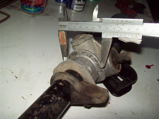
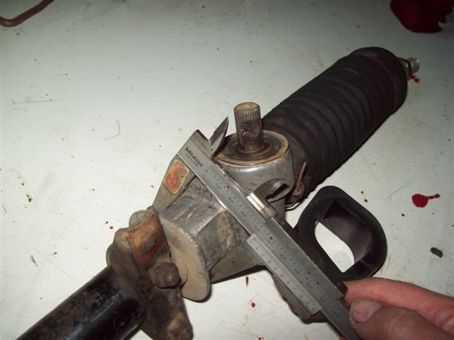
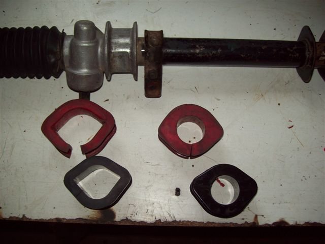
Nigel - From what you state it looks like a 240Z rack and further, the likelihood of a 280Z rack is remote as no 280Zs were sold in this country. The two dimensions on the mount are approx 43mm and 56mm, if anyone can confirm this with a rack they have off the car then it will suggest the new rubbers are duds as were the one fitted when I got the car 5 years ago - very strange!
-
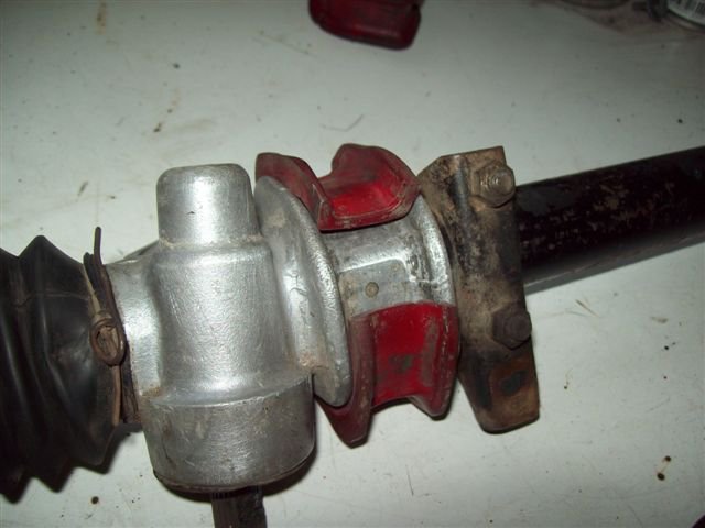
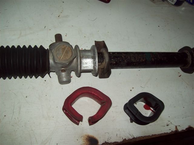
I'm just trying to refit the steering rack ('72, 240Z RHD) with rubbers I recently purchased. When I removed the rack I noticed the rubber (red) on the larger mount was not making a complete circle around rack. I now find that the new rubber (black) is even smaller. I appreciate that it will spread somewhat when I actually clamp it but it will still be some way short of completely encircling the rack. What's the go here? Were there different racks for 240s & 260s?
-
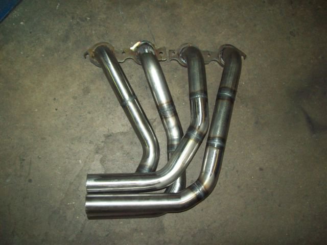
Here are some longtubes made up in Oz. It's the same place who will be doing my LS1 in a couple of weeks. http://www.bestmufflers.com/Information/Custom%20Systems/custom_exhaust_system_datsun_240z.htm
-

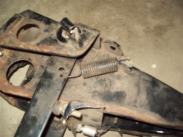
Clutch pedal return spring mount
Boy from Oz replied to camarojokester's topic in S130 Series - 280ZX
Apologies, I clicked on the thread via the 'last post info' column and didn't notice you have an S130. -

Clutch pedal return spring mount
Boy from Oz replied to camarojokester's topic in S130 Series - 280ZX
-
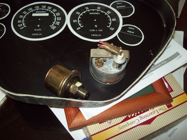
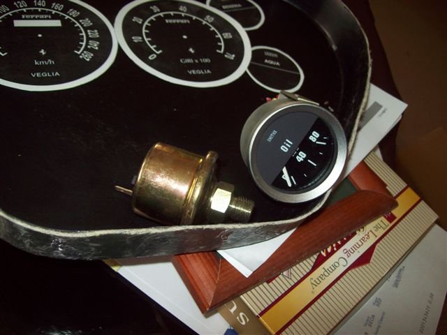
I would like to have a fuel pressure gauge on the dash so for safety it needs to be one with an electronic sender. So that the gauge won't look out of place with the other Smiths gauges I'm using do you think it feasible to use a 80 PSI oil pressure gauge (I understand the LS1 engine operates at around 55 PSI). Would the oil sender unit be suitable for the petrol (gasoline) pressure? Any instrument fitters out there?
-

Confirmation on where to seam weld before i start
Boy from Oz replied to Wedge's topic in Fabrication / Welding
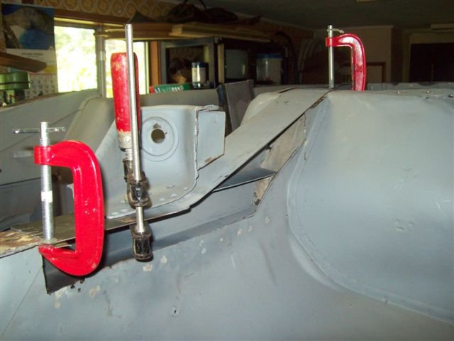
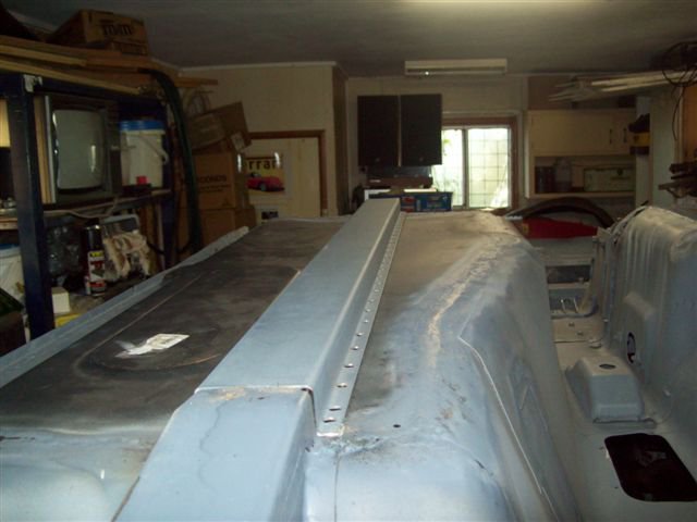
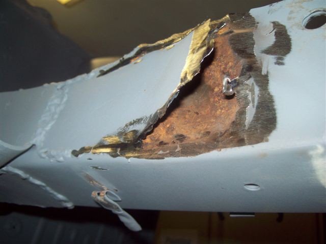
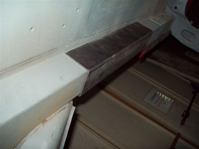
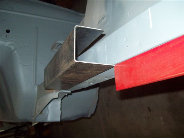
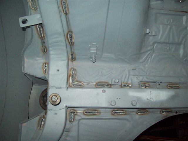
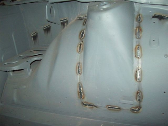
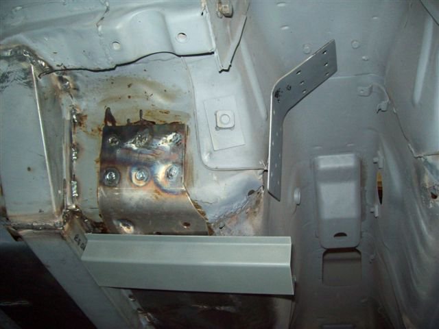
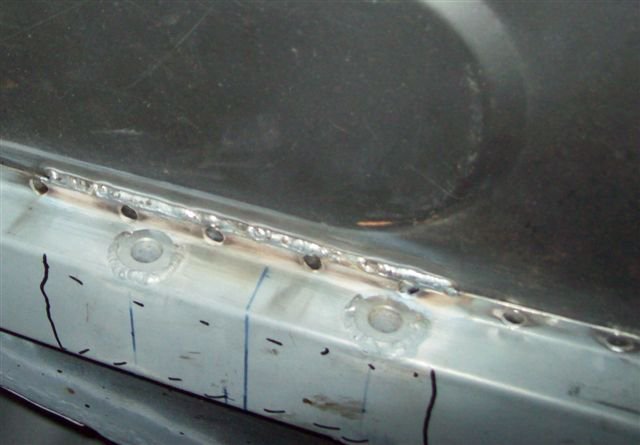
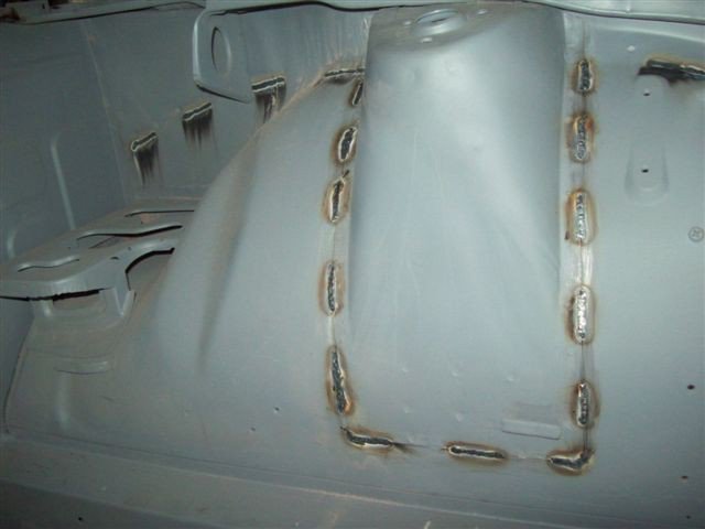
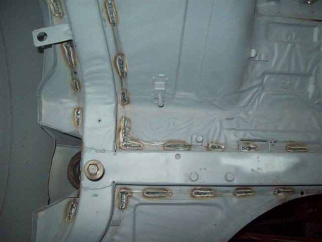
I agree with johnc about the greater importance of suspension loads and even though I’ve undertaken seam welding I’m skeptical of its worth. I think braces across the strut towers both front and rear is probably all that is needed. I have undertaken a complete rotisserie build for an LS1 installation mainly to address rust and poor repair problems. A front frame rail was in very poor condition and a previous repairer had just welded plates over sections. The floor needed relpacing so the seam welding was really a case of ‘well I’m here I might as well do it’. I do however consider extending the frame rails to the diff cross-member a worthwhile exercise. The first photos were not the completed job and I have in fact stitched the frame rails. I also fitted a 300mm ‘C’ channel over the front rails at the engine mount points to strengthen the area. -

Confirmation on where to seam weld before i start
Boy from Oz replied to Wedge's topic in Fabrication / Welding
Here is something you may wish to consider. It was my intention to weld every seam on the car but the chap I got to come and do it offered a pretty good reason not to do so. He has been involved in the preparation of race cars for 40 years so I figured he had some experience on such matters. In much the same way as rollcages have been adapted to serve a duel purpose, seam welding should try to emulate those same goals - crash protection and structural rigidity. That said, there is no need to weld seams which do not bear suspension forces or engine torque loads. By stiffening other areas you are reducing the impact attenuation properties which soften the deceleration if you hit something (or something hits you) and very importantly it allows any damaged panels to be repaired or replaced. If you have an overly rigid shell you don't know where it will give. Have you ever noticed cars that have had a tap in the back but the whole boot area retains it shape and the car folds around the rear window area. I wouldn't be welding the radiator surround or anything forward of the strut towers. Likewise I woudn't weld the rear frame rails rearward of the moustache bar cross-member. -
Agree - but all you need to retain from an OEM oil pan are the crankcase and bellhousing mounting points, the rest is free including any baffling you care to include, and a modified pick-up.
-
Do you actually need a windage tray with the Autocraft sump? If you need one it would be pretty straightforward to make yourself. Have you considered modifying an LS2 by aluminium welding to your own shallow front configuration. I think someone on here did that on a abortive 300zx install. Perhaps you could pick up a cheap front sump pan from a wreckers and have a play with it.
-
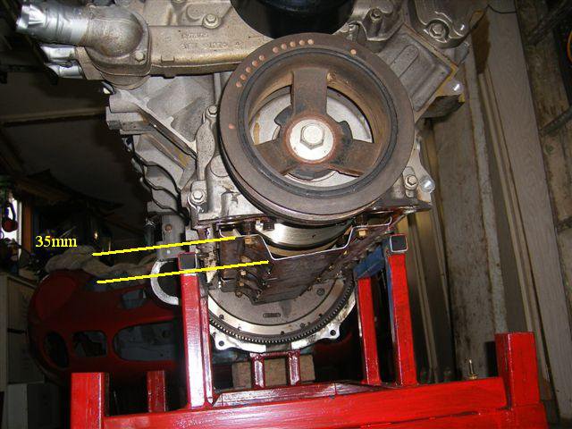
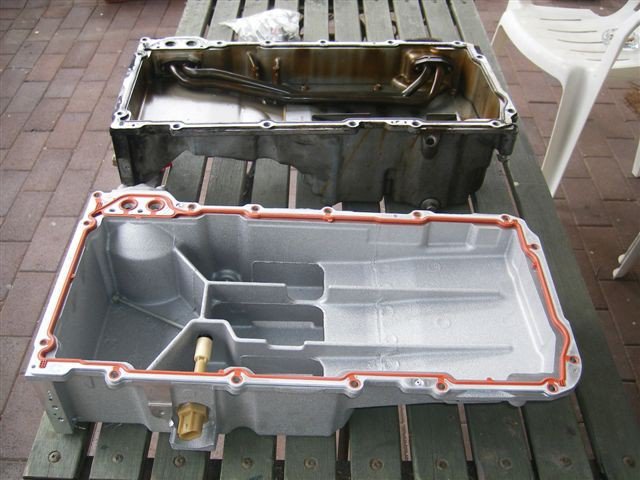
Unfortunately I now have the sump (oil pan) on so I can't be too accurate with this dimension, other than to say I just now measured the depth of the windage tray originally fitted to this Holden engine at 35mm. I would take that as your minimum depth of a fabricated pan. If this is for road use you must have a minimum 10mm clearance between the engine and chassis here in Oz. I've swapped to an LS2 pan for use in my S30. Hope this helps. Note: The windage tray in the photo is not firmly fitted into position.
-

Frame rails with integrated transmission mounts
Boy from Oz replied to Boy from Oz's topic in Fabrication / Welding
You have given me something to think about there. I'm halfway through attaching new seat support plates and there is a possibility of combining them with an extra cross-member. While the t56 transmission mount will also act as a cross-member I had planned on doing away with the standard diff front bracket as I'm fitting the GM diff with an RT style bracket, an extra cross-member in that area would be good. I'll probably wait until the tail-shaft and exhaust are fitted and see what clearance issues arise but I think it should be okay. Thanks. -

Frame rails with integrated transmission mounts
Boy from Oz replied to Boy from Oz's topic in Fabrication / Welding
That's probably some time off as the shell is still on the rotisserie. I have nothing unique in mind and just plan to mimic the JCI 280Z cross-member. I didn't have any issues with the cross-members but rather how they were attached to the shell. -
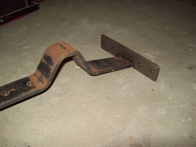
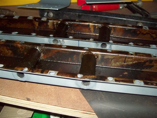
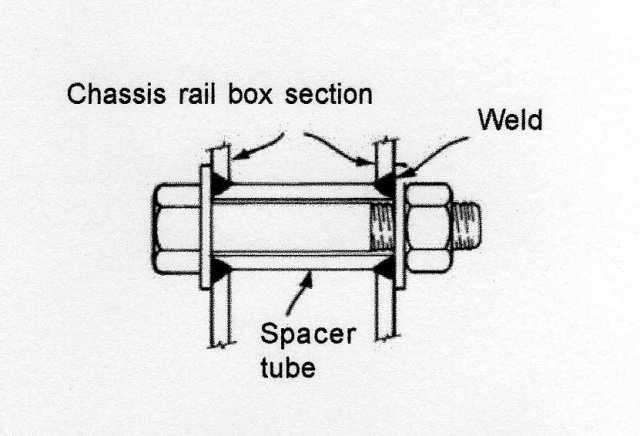
I was never really happy with the LSx/t56 JCI tranmission mounts, either 240 or 280 type, and as I needed new rails I decided to integrate mounting points into the rails. The rails are deeper at 30mm (about 1 1/4")but I figure the exhaust will probably be lower so it would not be an issue. Unfortunately I treated inside the rails before taking the photos and it is a bit difficult to see but I trust you will get the idea. I have TIGed the rails at intervals along the floor but have yet to MIG the new spot welds.
-

Why do doglegs rust? Can it be stopped?
Boy from Oz replied to Boy from Oz's topic in S30 Series - 240z, 260z, 280z
Thank you for your responses but I am particularly interested to know the design flaw which seems to always create rusting in the dogleg. -
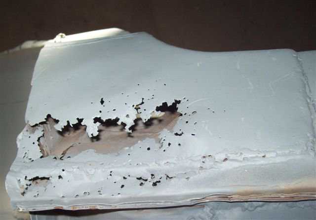
Apologies if this has been covered before. My car appears to have had at least two replacement dogleg sections on each side, meaning the panel has rusted at least three times. Has whatever causes this been identified and has any modification been known to prevent it from reoccurring? Thanks.
-
Here are a few photos of my car. The chap who did it has been involved in race car preparation for 40 years so I just let him go at it. It was my plan to weld the whole car but, as pointed out in an earlier post, he advised against this as any accident could significantly distort the alignment of the shell rather than just keeping the damage local. I don't intend to race it at all and did it mainly for an LS1 installation.
-
Could you post a photo or two on this - it sounds like a very sensible idea. Thanks.
-
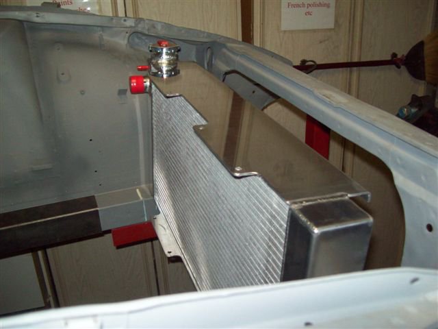
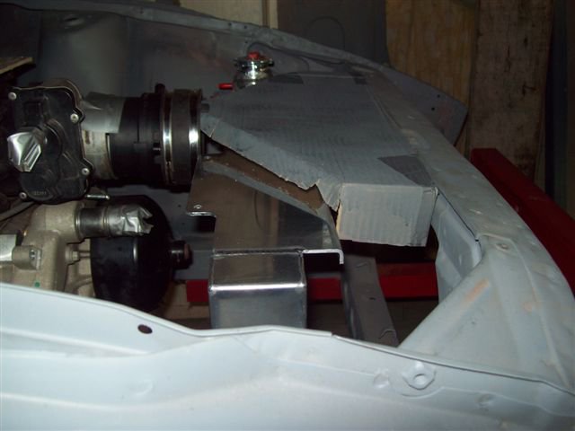
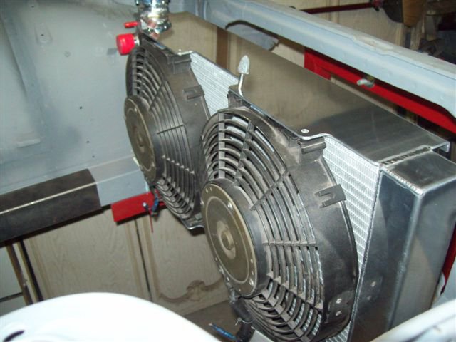
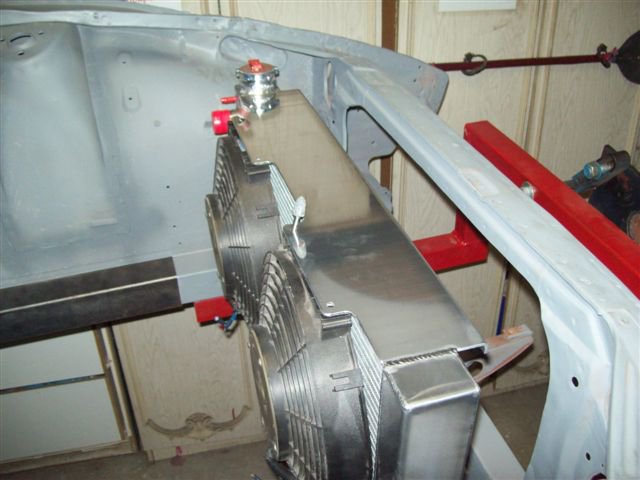
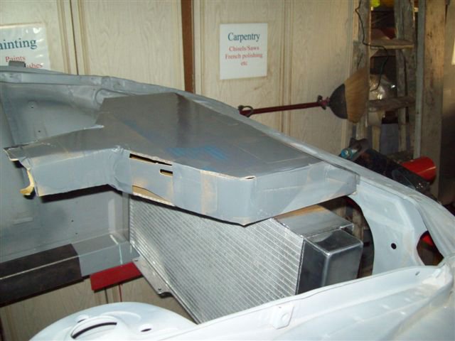
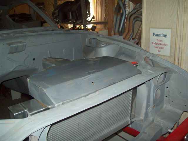
I wonder if anyone could provide some ideas on a cold air intake design. Over-the-radiator (OTR) cold air intakes are all the rage down here for LSx engines (not sure about the US), I personally am more taken with the aesthetics than the reports of improved engine performance. I have just had a radiator made that will allow me to run an OTR intake on my LS1/S30 and I have made a mock-up based on the standard commercial design. It looks a bit bulky and I thought to scale it down a bit. If the throttle body on the LS1 intake is around 85mm dia, (64cm2) is there any need for the cross-section of the intake to be any larger, other than at the mouth where the filter restricts air flow? Why do you think the commercial intakes have such large cross-sections right up to the throttle body? Thanks. Commercial intakes = http://shop.ebay.com.au/?_from=R40&_trksid=p4522.m570.l1313&_nkw=otr&_sacat=See-All-Categories
-
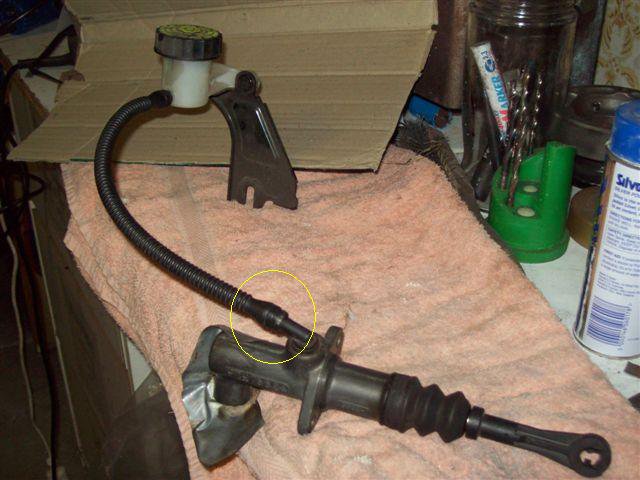
I trust this is not too OT but I had intended to fit a GTO clutch m/s with my LS1/t56 install. I am concerned by the failures of these cylinders experienced by 'm1noel' and 'RB30X'. I've had a close look at the units and thought the problem might with the swivel connector on the line from the reservoir to the m/c, rather than the cylinder itself. Could either of those gentlemen advise me whether the leak was noticed in the engine bay or the cabin. Thanks.

