-
Posts
541 -
Joined
-
Last visited
-
Days Won
2
Content Type
Profiles
Forums
Blogs
Events
Gallery
Downloads
Store
Everything posted by Boy from Oz
-
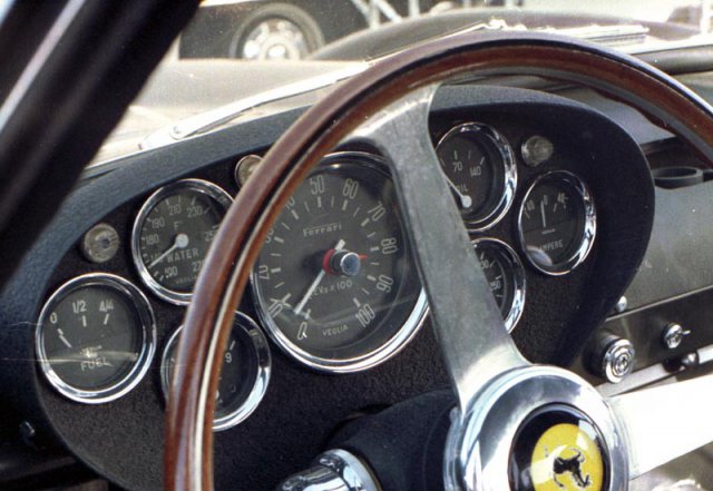
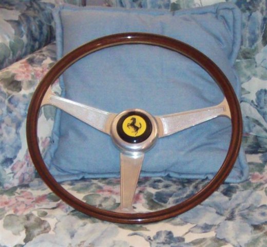
If you are referring to post #690, that is a hard top (berlinetta/coupe) kit. Re: Steering wheel - "Steering was by an elegant Nardi wood rim wheel of 400mm diameter. The three engraved aluminium spokes were gently dished and the central horn push carried the traditional Cavallino Rampante motif on a yellow background". Bluemel. K, Pourret. J, Ferrari 250 GTO, Bay View Books, Devon, UK, 1998, p.34. Probably the best you can do now is the Nardi Anni 60 which has a 363mm rim at around $600US. I think mine came off an Alfa or Lancia and I picked it up off the Italian eBay for $250US with the Nardi horn button. I then obtained a Ferrari horn button for about $35US. Measuring the wheel is from centre of the wood rim to the centre of the wood rim and not the outer edge. Many will advertise a 380mm dia when in fact it is a 360mm (or 363mm according to my Nardi packaging box). Apart from the original being a larger overall diameter the horn surround is also a larger diameter. You can possibly track down an original but even the replicas start at around $1600US! Here are photos of the real thing and mine.
-

Bad Dog 240z Frame Rails
Boy from Oz replied to matt_w's topic in Brakes, Wheels, Suspension and Chassis
I had a similar issue with my floor pan and a 6" length of 4"x2" timber and a hammer soon fixed it. I assume you have removed the carpet, so just position the timber on the floor above the rail and whack away. You'll see that it flattens out fairly easily. Like all good panel work, a thousand small hits are better than one big one. -
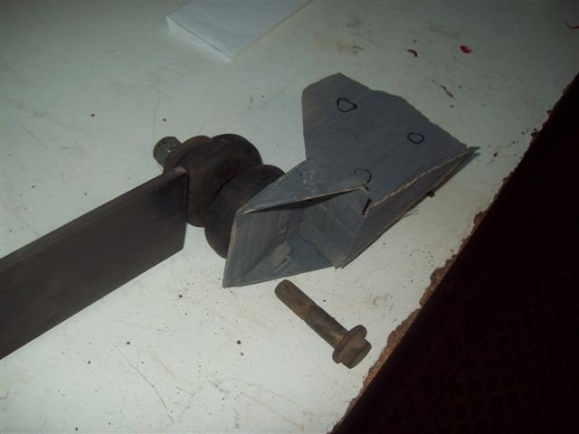
Okay - thanks for the info, looks good. You might want to consider a three point mounting for the lower front brackets, though with the upper bracket (which I don't have) you may not need. I've utilised the two existing mounting points and propose to add a third which will mount through the double layer section of the transmission tunnel to a nut and spreader plate inside the cabin. Here is an early version beer-carton template to illustrate the three bolt concept.
-
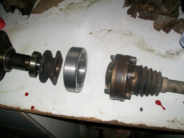
Great work. I'm interested in this as I'm trying to fit a GM diff and I have a couple of questions. It appears that your input shaft is on the centreline of the transmission tunnel, if so, does that mean you are going to run odd length drive shafts? Have you matched the angle of the diff to the angle of the motor/transmission? Do you need upper AND lower front mounts to limit movement, or is it merely to distribute the forces radially around the mounting area? (I intend to use a spacer through the rubber mounts to seat a large washer and nut on the mounting bolt, thus only requiring one bracket/s , i.e. lower). Will you need to make an adaptor from the outer CV to the Datsun rear axle shaft like I had to? I had thought of using the Modern Motorsport adaptors but the diameter was too large.
-
I'm fitting an alternative diff http://forums.hybridz.org/showthread.php?t=138675 and just finalising the nose mount. I have become muddled over where the forces might be applied. I was designing the mount to take forces in the vertical plane, i.e. lift the nose under power and drop it under deceleration, but I'm now confused at to whether there is a reaction force through the diff mounting points which actually propels the car. If that is the case and the moustache bar is flexible then a considerable horizontal would be placed on the front mount. Some designs I see only appear to address vertical forces. Help!
-

GM LSD IRS diff in S30 - fits like a glove.
Boy from Oz replied to Boy from Oz's topic in Drivetrain
I'm so close to finalising this but wonder if someone can provide a bit of information. I want to know the angle of the mounting plates which are attached to the transmission tunnel. I don't have access to an inclinometer. I searched for a drawing of the R/T mount showing dimensions (to work out the angle) which I'm sure I've seen before but couldn't find it. Thanks (edit - took a few measurement and figure it's close enough to 7 degrees) -
A very interesting site and when I looked at it the name 'Merlin' rang a bell. The chap credited with creating the first 250 GTO kit - the Eagle GTO, but best known as the Alpha - was Merlin Cafono going by the name Barry Goldstein (see post #419). I see that the 'artist' responsible for the Merlin is again Merlin Cafono but this time going by the name Baryla Khodorkovsky. Quite a character I would imagine but very talanted just the same. Also the rear closely resembles another Ferrari of the 60s-70s - a Daytona perhaps?
-

GM LSD IRS diff in S30 - fits like a glove.
Boy from Oz replied to Boy from Oz's topic in Drivetrain
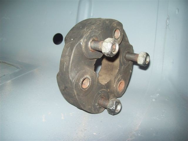
I understand I can utilise ‘perfect alignment’ as I will be using Jurid couplings as fitted to GM donor car. With the conventional Cardan or Hooke joint perfect alignment would result in brinelling, i.e. too much wear on the needles, however, the Jurid acts more like a CV joint and has no metal to metal contact points. -

GM LSD IRS diff in S30 - fits like a glove.
Boy from Oz replied to Boy from Oz's topic in Drivetrain
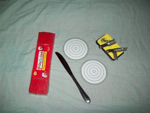
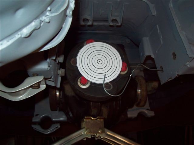
Yes and no. I have been installing the engine and gearbox to see if there were any alignment issues with the diff. Again it is all technically good news. Using the laser pointers and targets the gearbox output shaft and the diff input can be perfectly aligned. Just haven't hit on a front mount design that I'm happy with. I'm sick of crawling under to car to work on this so I'm putting it back on the rotisserie on Wednesday. Sometimes life can be more enjoyable standing up! Send me a PM with you mobile if you are interested in having a look. -

long tube ls1 headers
Boy from Oz replied to BOBBY BATES's topic in Gen III & IV Chevy V8Z Tech Board
It's been done on a RHD with JCI mounts. I'm not sure how the setup would fit on a LHD. http://forums.hybridz.org/showthread.php?t=143936 -
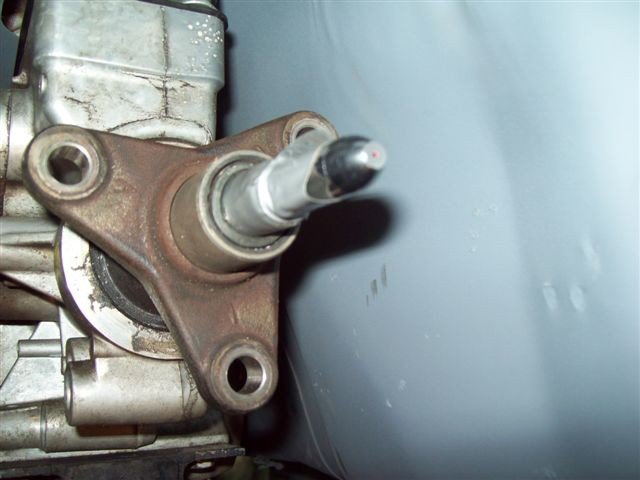
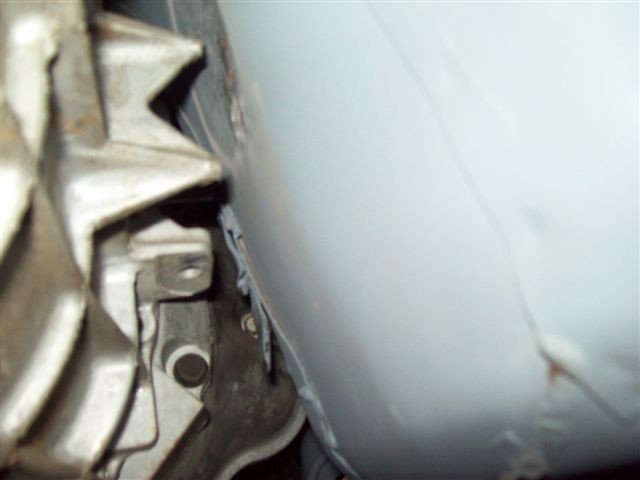
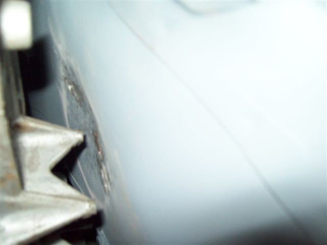
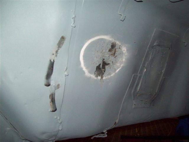
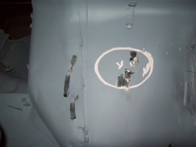
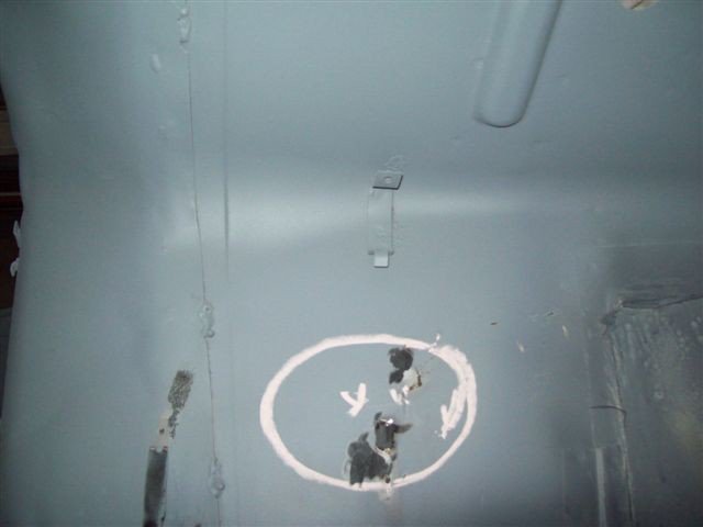
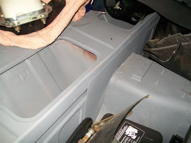
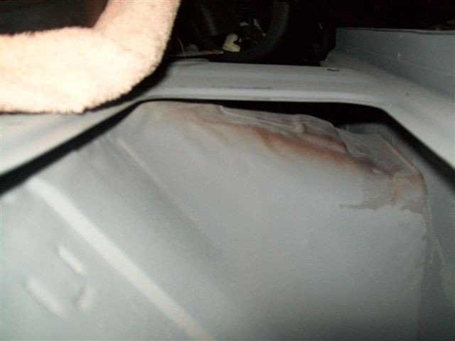
I don't know that anyone has posted this before so I took a few photos of the reshaping required of the transmission tunnel to clear the reverse light switch on the tremac t56 six-speed, mated to an LSx. Just a few knocks with a hammer is all that is required. The grind marks are where I removed two clips, so that may help others to further identify the position. Would others who have done the swap confirm this.
-

Advice on radiator location
Boy from Oz replied to Boy from Oz's topic in Gen III & IV Chevy V8Z Tech Board
They use K&N filters - look up Australian eBay and look under 'OTR' www.ebay.com.au From what I can tell there are three options for the radiator; - a gooseneck extension with the overflow going out of the system - a pressurised system where the overflow is stored in a tank and feed back to the system - a recovery tank where there is a two-way pressure cap which allows overflow to a non-pressurised tank but a scavenge line which allows the overflow coolant back through the cap when there is a vacuum in the system. Which best suits an LS1? -
I intend to fabricate an over-the-radiator cold air intake (see photo). This will require a wide radiator that is mounted relatively low. I have taken a few measurements (see sketch) and the water pump outlet is approximately 2" above the radiator hose point. I would just like some comments about the proposed location. Will I need to fit a longneck radiator cap mount or is there some other way I can purge the system of air?
-
I couldn't help but notice a degree of interest in 60s -70s racing cars on this thread. If you are not already familiar with the site below then there is a good chance some USA, UK, Canadian, Oz and Kiwi members will be up very late tonight reading some of the enthalling posts. http://forums.autosport.com/forumdisplay.php?s=&forumid=10 Jerry B - If you are so keen on Lotus you missed a chance at a collection sold in Sydney a few months ago.
-
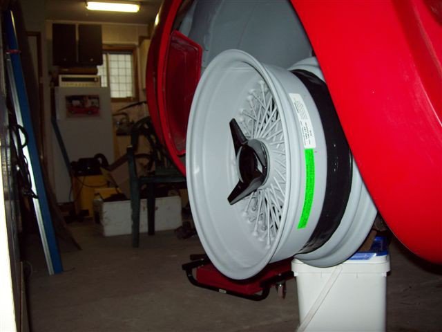
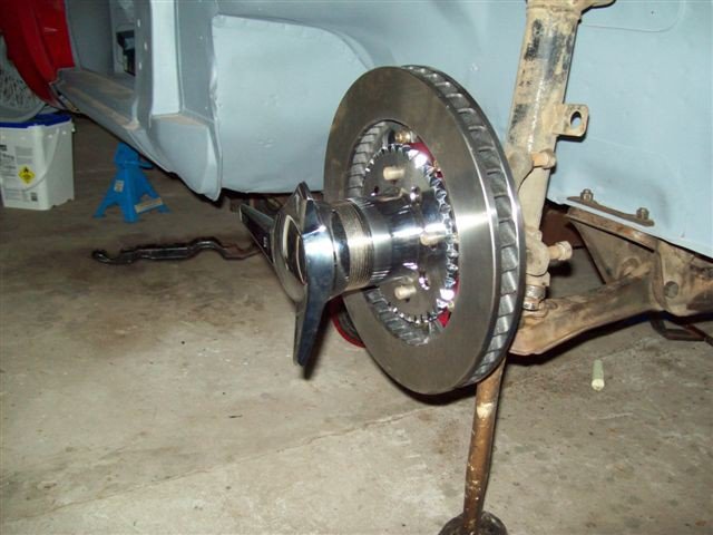
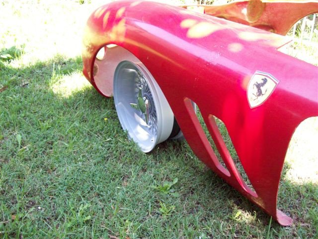
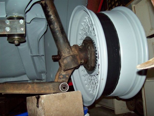
With the cost involved I feel like I have been a one-man stimulus package, but I have my Daytons ... well two of them anyway, and I have some information which may be of interest. Back in an earlier post I stated I wanted to keep to the original look as much as possible and I was hoping to fit 6" fronts and 7" rears. If that did not work I could go for the 7" front and 8" rear. With many folks running up to 10" rears I expected I would have to lengthen the rear control arm to widen the track but I wasn't sure by how much. To be safe I purchased the 7" rims first. Well surprise, surprise ... The 7" reverse-laced rims fit the rear perfectly. These rims have a 2" backspace which means a 6" frontspace (a 7" rim is actually 8" in overall width, as I'm sure you know). I contacted a GTO kit owner and it was confirmed that the 10" rims only have the same 6" frontspace but have a deeper backspace. In my view this means the critical measurement on GTO rear rims is the frontspace distance - 6" frontspace if you want the rim 1" in from the lip of the guard or 7" frontspace if you want them flush. Having sample fitted the 7" rims to the front I'm confident the reverse-laced 6" rims should fit perfectly on the front. Also important to state I went for 16" rims so that I can fit this parking brake. http://forums.hybridz.org/showthread.php?t=141819 By the way that's the finish colour but the flash has made them appear a little paler - I kinda like the Targa Floria look. Come down here for your R&R, just like the old Vietnam days. It's bloody hot I can tell you.
-

GM LSD IRS diff in S30 - fits like a glove.
Boy from Oz replied to Boy from Oz's topic in Drivetrain
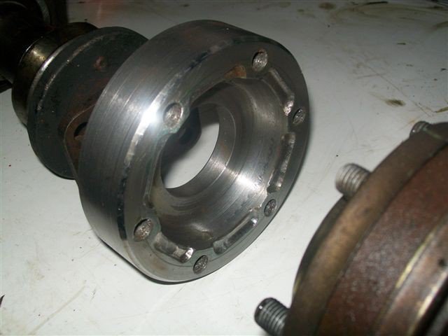
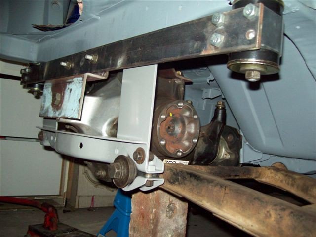
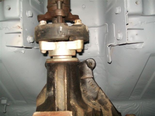
The rubber universal is too close to the bolt head on one of those four points (see photo). I could only go 2-3 mm before the uni would rub on the bolt. Material that thin would need gussets and that would create more interference. -

GM LSD IRS diff in S30 - fits like a glove.
Boy from Oz replied to Boy from Oz's topic in Drivetrain
Thanks for the comment. I considered that but there are two issues associated with a vertical attachment. Firstly, clearance for the parking brake cables and secondly, as you guessed, the area inside the car above the tunnel at that point (between the two storage areas) is difficult to access, particularly to mount a spreader plate. Registration requirements down here basically allow you to replace or add to the structure, but not remove any of the original. Thinking now of moving the diff 10mm off-centre with a RT style mount, and using different length axles. Any thoughts on that? -

GM LSD IRS diff in S30 - fits like a glove.
Boy from Oz replied to Boy from Oz's topic in Drivetrain
Well the glove is not such a perfect fit after all. Having all sorts of trouble configuring the front mount. Thought I could just adapt the Ron Tyler mount but the rubber universal is simply too close to the original mounting twin bolt heads on one side to allow this. Further, those twin points are some distance from the mounting points on the front of the diff making for awkward loads. There really doesn't seem to be any existing points that I can attach a front mount to. The only idea I have come up with is to weld strengthening plates to the curved portion of the body shell and install a cross piece to pick up the two mounting points on the diff - including some kind of energy absorbing fitting. I would appreciate any suggestions people have as to an alternative. Thanks -

Holden brakes again - ? for Aussies
Boy from Oz replied to GeeZ's topic in Brakes, Wheels, Suspension and Chassis
Post some photos of the caliper and the pads and I'll see what I can track down. -

FYI - Vanilla Sky Ferrari GTO Replica Listing
Boy from Oz replied to SpeedRacer's topic in Body Kits & Paint
Is there any chance you could get out there with a camera and get some photos of the sliding windows. I have been planning on doing that to mine and I would like to know how the front pane of glass can slide back that far when the opening appears to narrow towards the rear. It might be that the bottom guide is recessed deeper at the rear, with the upper and lower guide in fact parallel but not square to the sill of the door - if you follow. I would be keen to know how it was done. Thanks -

GTO T-56 shifter dimension request…
Boy from Oz replied to BRAAP's topic in Gen III & IV Chevy V8Z Tech Board
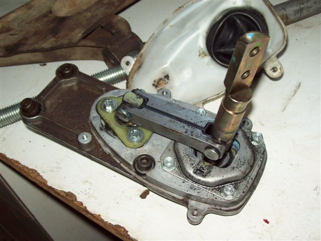
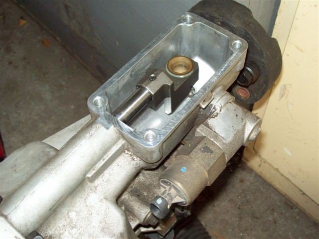
Paul - I might need a little more clarification to give you the exact measurement you want. I trust there is sufficient information in these photos for you to see exactly what the components of the assembly look like. I have attempted to give you a couple of dimemsions but if you need more just ask. -

velo rossa body kit
Boy from Oz replied to MIAMI240Z VELO ROSSA's topic in S30 Series - 240z, 260z, 280z
What you have there is not a Velo Rossa but a 250 GTO coupe kit - the roof of the S30 is retained as the roof of the coupe. The Velo Rossa is a spyder, i.e. open sports car. http://www.kitcarz.com/ . The kit in your photo is from a very early mold, Alpha probably, but a photo of the rear tail-light arrangement may help to identify it further. There is a fair bit of Velo Rossa and coupe information here and people willing to answer questions. http://forums.hybridz.org/showthread.php?t=115734 -
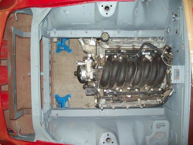
WAH HOO!... In hoping to run longtudes I've been working on new mounts to offset the engine back to the center in an attempt to give more steering shaft clearance on my RHD, now you say it can be done with the standard JCI mounts - fantastic. If you post more photos I swear I never call Russell Crowe an Australian, ever again! Along with Crowded House, etc, etc.

