

RTz
-
Posts
2941 -
Joined
-
Last visited
-
Days Won
23
Content Type
Profiles
Forums
Blogs
Events
Gallery
Downloads
Store
Posts posted by RTz
-
-
hehe Matt, well with all your rhetorical remarks lately towards the admins, can't say you didn't see the names coming with the way you've been acting. All in good humor or not...
 *sits and waits this one out*
I think I made my point in the 'other' thread. The 'tude can be superseded with an adjustment. Time will tell. 'Till then, DEFCON 4 will remain in effect.
Enough about this... we have better things to discuss
-
The one with the single yellow wire is the temp. 'sender'. Its only function is to provide a signal for your temp. gauge. It has no bearing on the EFI system.
-
always wondered who came up w/ making those titles under the user handles, I looked around user cp and couldn't find anything, then said oh well screw it.
http://forums.hybridz.org/showthread.php?t=130544
I'm sure if you just check them periodically and make sure they are torqued down they will hold up fine. Maybe that stud got stripped?
I don't know what Matt's particular issue is. I've used spacers before with no significant issues. I tend to agree that a proper torque should do just fine. However, after his experience, I can't say I blame him for pursueing some 'peace of mind'.
-
You were at DEFCON 1. Catch my drift?
Loose the crass, keep posting in real English, and I'll ditch the DEFCON 4. Fair enough?
-
-
(and hey look admins everything is spelled right and punctuated correctly!!!)
Good job! I guess we'll keep you around for a while longer
-
u no theirs a long tip n the camshaft, and the crank angle sensor(CAS) also has a long tip, inorder to line up the CAS to go in.my CAS is fine. just the longer tip from the camshaft is broken off.now its left with two peice inside the CAS, where its suppose to be one.if its stil hard to determand, ill post up picture for better understand. thanks
Your writing habits do not conform to our rules. I asked you nicely once and you chose not to take me seriously. Hopefully you will take me seriously this time.
Before you post again, I want you to read all of our rules. Please pay particular attention to #5...
http://forums.hybridz.org/announcement.php?f=65&a=2
If you post in this fashion again, I will suspend you for 7 days. After which, if you continue, I'll make the suspension permanent.
Please respect our rules.
-
i just removed my crank angle sensor from the cam today, so i can replace my timing belt.when took off i notice that somthing broke from the cam(the little tiny teenth thing that lines up with the crank angle sensor) that little peice from the cam was broken off from there. my freind say now, i will need a new cam. but before i do as my freind say, i want to no if its necessary or can i just leave it as is, and it wouldnt be a problem. please help..
If the cam is indeed broken, you're likely stuck with replacing it. A picture would help greatly here.
so your saying if i dont replace it, it will not start the car rite.That sensor is the single most critical sensor in the entire EFI system. There is no way to bypass it (with the stock ECU). It must be in proper working order.
P.S. please fix your shift key.
First and foremost, pay attention to what your saying. You mention cam AND crank. Which is it?Evan, Nissan calls that sensor a "crank angle sensor" even though it is, in fact, a cam angle sensor.
-
nice architectural shots Ron!
is that with the extension tube?
Depends on what tube is mounted but, for example, the 36mm tube reduces maximum focus distance down to around 4 feet (with my 200mm lense)... so no 'architectural shots' for the tubes.
-
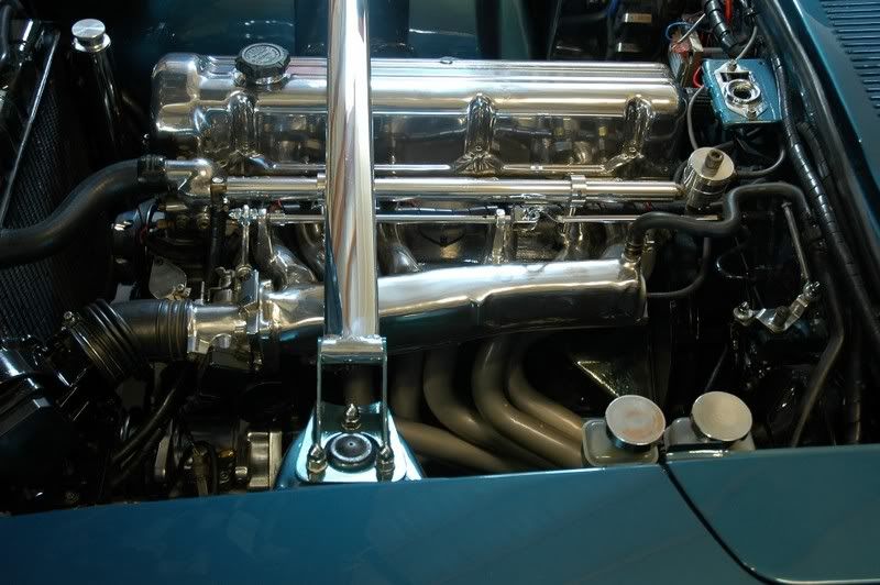
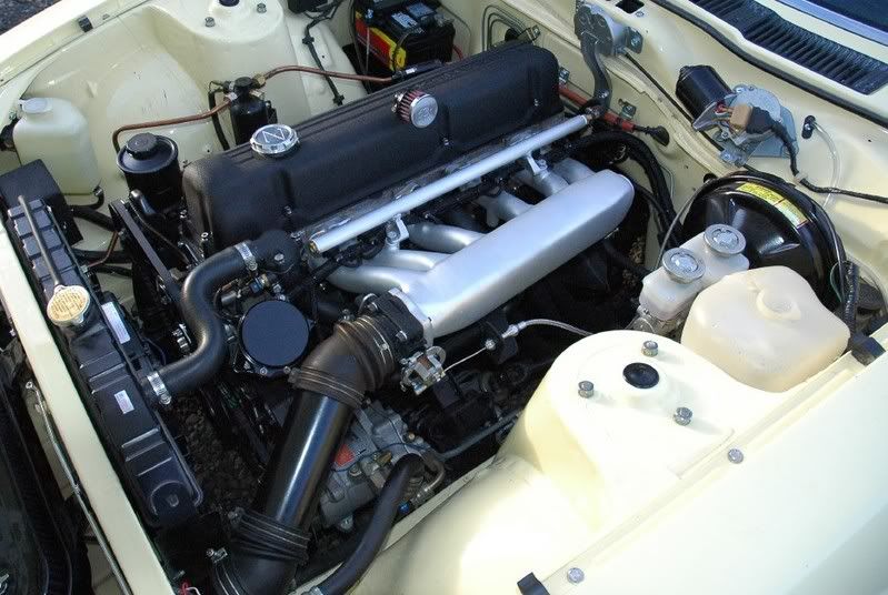
Ljet clean-up...
Aftermarket EMS clean-up...
-
OHSU campus...
BRAAP and I worked on this building for months.
Its difficult to capture its odd shape, a combination of compound angles, on a curve...
Located above Portland, the view from inside can be stunning at times. Some of BRAAP's earlier night pictures were taken in this building, pre-glazed.
The skeletonized structure on the right is an aerial tram, one of Portland's more controversial projects...
-
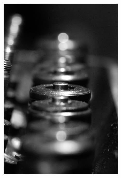
SBC Valve-train...
-
Jonas,
Whether you problem has to do with a spark plug or people at a retail location - your wisest solution is to start at the the ROOT of the problem.
In this mindset yes i have more than enough confidence in my comment.
In some cases, you point of view isn't completely unreasonable, but in many cases it *is* unreasonable. That's what Mike meant when he said "blanket statement". You can't say that about all entities.
Does the President know about all your speeding tickets? Nope. He's got bigger things to worry about. He delegates that authority to someone else. That doesn't make him a "corrupt ahole".
Does SuperDan know everything that goes on in this forum, including all the conversations and actions between every member and admin? Nope. Its not because he doesn't care... its because its an impossible load for one person. That's WHY we have multiple admins. He delegates that authority to people that he trusts. That doesn't make him a "corrupt ahole".
Not gonna allow it...That statement is synonymous with asking you to stop. This is not the first time you've been asked to cease and you continue arguing. If you've been asked to stop, please do so. If you feel strongly enough about your position, then PM that admin and discuss it with him. Continuing to publicly banter is not your wisest choice.
-
Melinda Gombert has this strip in her signature. Made me smile...
-
You crack me up Jeff... you create that which belongs in the Smithsonian, equally at home in the Fine Art dept. AND Science & Technology... and then install it on a old Datsun... I love it!
Thanks for sharing. -
did the 240z come with stock option for this?
Uh, no.
-
We don't have the accumulation you have, but we have had a fair bit of snow fall recently. Couple day's ago it was snowing profusely... and ambient was ~50F
. -
Careless teaching me to be careless...
-
Truce. Until next time...
May the Force be with you
-
A pair (or more) of resistors can be used to PROPORTION voltage. That is a voltage divider. That is what you're describing. There is no voltage loss, just a rearrangement. Total circuit voltage will always be the same, regardless of how many resistors are used.
And that will be the end of this debate.
It is seriously off topic anyhow (not your fault).
-
Technically I don't think that your first picture is a "circuit" the definition that I know requires a path for current. Doesn't the DMM complete the circuit?
In that circuit, the LED 'see's' 5v. The resistor is only limiting the current. Industry calls that a "current limiting resistor", yes?. Why do they call it that? Because that's what its doing. They don't call it a "voltage limiting resistor" because its not limiting the voltage.
Reducing the current, at the same voltage, decreases the wattage, and thats what keeps the LED from burning up.
The voltage on one end of the resistor will be lower than the voltage on the other.That statement, on its own, is misleading.
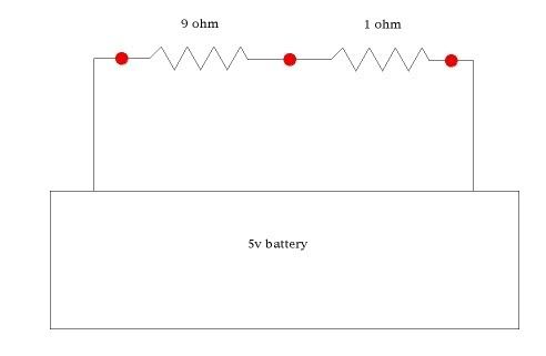
In this cuircuit, measure the voltages at each of the red dots, in any configuration you wish and write them down....
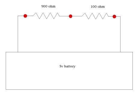
Do the same with this circuit....
You'll notice that your voltage readings are exactly the same in each circuit, even though there is 100 times more resistance in the second circuit. Why? Because resistors do not IMPEDE VOLTAGE.
However, put an ammeter in line of both of those and you see the total circuit amperage is 1/100 in the second circuit. Why? Because resistors do IMPEDE CURRENT.
Resitors impede current. That is their function. That is what the do. Every English written modern textbook says so. Resitors do not impede voltage... not one modern textbook says they do.
-
Top of the page... http://www.doctronics.co.uk/resistor.htm
"What do resistors do?
Resistors limit current."
Top of the page... http://www.kpsec.freeuk.com/components/resist.htm
"Function:
Resistors restrict the flow of electric current, for example a resistor is placed in series with a light-emitting diode (LED) to limit the current passing through the LED."
No reference to dropping voltage.
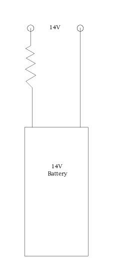
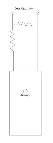
I have no idea what that picture is showing. It looks like you are applying 14.6 volts across the lead. And then 14.6 volts across the resistor. What the display is showing is just the voltage you are applying.This is essentially what my picture above is measuring...
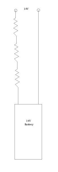
You can put as many resistors in series as you like and the voltage won't drop...
I'm having trouble seeing what's in your pictures, but it looks like its a voltage divider. Voltage dividers require two or more resistors arranged in a specific manor.
Like this...
Why does the voltage drop? Because you 'shorted' the circuit to ground. That's the way I understand it, anyway.
Sorry I may have gone a little overboard with the pictures. Any chance to play with the Keithley sitting on my desk. That thing is so cool
No apology... I like pictures
-
-
I'm going to attempt to remove the size 13 from my mouth...
Post 12 is accurate. What I said about voltage dividers is accurate. However, I didn't stop to think that adding a resistor in line with the AFM would effect the existing voltage dividing network of the AFM. In retrospect, it should influence it.
I have never tried it because I think its the wrong choice, for the two reasons I mentioned in post 13.
Sorry for the confusion.
 *sits and waits this one out*
 )
)


 Doesn't the DMM complete the circuit?
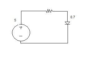


Admins, they are so clever!
in Non Tech Board
Posted
Sorry Woldson, I deleted your post. Lets let it go.