
JustinOlson
-
Posts
1710 -
Joined
-
Last visited
-
Days Won
3
Content Type
Profiles
Forums
Blogs
Events
Gallery
Downloads
Store
Everything posted by JustinOlson
-
spaceframe 240-Z update
JustinOlson replied to boodlefoof's topic in Brakes, Wheels, Suspension and Chassis
You need a better website host... I'd recommend google blogger. It would be a great way to have more bandwidth to share your project with the community. I'd be willing to transfer over all of your current info from your website to help you get it going. http://www.blogger.com/start Justin -
Drag/Track Car Cage
JustinOlson replied to JustinOlson's topic in Brakes, Wheels, Suspension and Chassis
Welding 4130 Steel for Race Cars During the WW II era 4130 high strength steel was used for some aircraft components. At that time oxy-acetylene was the welding process of choice for many of these items. The preheat and slow cooling inherent with that process made welding the nominal 0.30 carbon steel relatively straight forward (assuming one could oxyacetylene weld!). However with more modern welding process like TIG and MIG, the cooling rates can be much faster and care must be taken to avoid forming high hardness and brittle Martensite on cooling transformation. On heavier sections preheat and post weld heat treatment should be used. With the proper post weld heat treatment strengths of 200,000 psi can be achieved with reasonable toughness by tempering the Martensite that forms in the heat treating process. However when welding race car tubing, preheat is not often used nor are the parts post weld heat treated. Most of the tubing used for race car construction is referred to as normalized. This refers to the heat treatment and cooling rate the tubing was subjected to in manufacture. Most normalized tubing will range in tensile strength from 100,000 to 115,000 psi. This can be welded with the proper filler metals to achieve similar strengths. Although there are more weldable grades of steel (those with lower carbon content from 0.06 to 0.15) in the 100,000 to 115,000 psi tensile strength range readily available for plate and sheet, 4130 remains a commonly used grade for tubing. Just be sure to take the precautions noted when welding. PROPER FILLER METAL CHOICE FOR WELDING 4130 In the mid 1970’s, while managing an R&D group for a leading welding filler metals manufacturer, a phone call was received from a dragster chassis builder. They wanted to weld 4130 tubing and needed a filler metal suggestion. Being a “car buff,†a number of alternatives were considered to provide the optimum solution. After careful review of their requirements and desired welding practices, the solution was defined. They were welding 4130 normalized tubing, it would not be heat treated after welding, preheat was not desirable and most of the weld joints were intersecting tubes that required fillet welds. The best filler material to use was a low carbon alloy now called ESAB Spoolarc 65 (meeting an American Welding Society (AWS) ER70S-2 specification). The main objective is to produce porosity and crack free weld deposits. This welding alloy has a very low carbon content, nominally 0.06, which can handle dilution into the relatively high (in terms of weld metal), 0.30 carbon in the 4130. The resulting diluted weld deposit has a tensile strength of approximately 590 to 620 MPa ( 85,000 to 90,000 psi.) The actual strength will depend on the amount of dilution with the 4130, weld bead size and material thickness. This is usually an under match for the 4130 tubing which could have a 760 to 800 MPa (100,000 to 115,000 psi) tensile strength depending on how the material was processed. [Added Note: some normalized 4130 tubing may be only have a 90,000 psi tensile strength, it depends on the manufacturer] However, if extra joint strength is required, a slightly larger fillet size or gussets can be employed. In addition, this welding wire contains small amounts of aluminum, titanium and zirconium. Although these elements were initially added to handle welding over mill scale, they also contribute to a less fluid weld puddle. The benefit to the welder is, it is easier to make out of position welds. Note, it is suggested all welding on 4130 be performed on ground surfaces free of oil or grease (to keep the hydrogen levels as low as possible). Several years after making this suggestion, when looking at a catalog from the dragster chassis manufacturer, it was interesting to note they were advertising their use of the ER70S-2 filler metal for their 4130 welding. In fact, they were offering it for sale for those customers purchasing frame parts and doing their own welding! The Internet was searched to see what current recommendations were being made for joining 4130 tubing. Several hundred sites were found that recommend the ER70S-2 welding rod/wire alloy. It was the predominant recommendation. Typical of the Internet however, there were many improper descriptions of why this alloy should be used and several incorrect recommendations. Need a higher strength deposit? If a higher strength weld is required for perhaps a butt weld that cannot be reinforced, strengthened with a gusset, or put in a less critically stressed area, there are possible solutions. The use of Spoolarc 83, which contains 0.50 Moly, will provide a weld deposit with higher strength. When diluted into the 4130 base material a weld tensile level of 760 to 800 MPa (110,000 to 115,000 psi) can be achieved. If this higher strength welding wire is employed, a minimum preheat of 65 degrees C (150 degrees F) is suggested. Weld strength can increase to a level slightly higher than with Spoolarc 83 (AWS ER 80D-2). Do not use an austenitic stainless steel such as an ER308L, (which is recommended on some Internet sites). Diluting this or similar austenitic stainless alloys with 4130 can lead to cracks. Also, consider that providing a higher strength weld deposit cannot compensate for the reduction in strength that will occur in the parent metal immediately next to the weld deposit. If the part will be heat-treated after welding to achieve very high strength, a matching chemistry filler metal to the 4130 should be employed. Because of the relatively high carbon, a minimum of 200 degrees C, (400 degrees F) preheat and very slow cooling after welding should be used to avoid cracking. After welding, the part can be heated to 870 degrees C (1600 degrees F), quenched in oil or water then tempered back to say 370 degrees C (700 degrees F). A complex cycle, but this will result in a tensile strength of approximately 1380 MPa (200,000 psi). Since the weld is the same chemistry as the base material, it and the heat-affected zone will have the similar properties as the base material when heat-treated. All critical welds of this type should be inspected for internal soundness to assure they are free from cracks. End Of Abstracted Article OTHER PROBLEMS ENCOUNTERED In addition to the filler metal selection issues mentioned, some additional cautions should be followed. Many fabricators use TIG welding and make very small, concave fillet welds. There seems to be a feeling that the smaller the better. This raises several concerns. First there is little filler metal used to make these very small welds. Therefore the weld consists mostly of the high (by welding standards) carbon from the 4130 base material. This can cause cracking since there is no preheat or postweld heat treatment being used. Also cooling rates for these small welds, especially when using TIG, can be quite high. Therefore one suggestion I had made in the article (removed from this abstract) was that some stainless steels filler materials could be used. This is also mentioned on a number of Internet sites. However with these small fillet welds there is only a small amount of stainless filler in the deposit and possibly a significant amount of the high carbon base material. This combination can lead to a crack sensitive deposit. It is suggested stainless filler metals not be used for welding 4130. Making an analysis of the resulting weld chemistry for varying amounts of filler metal dilution creates a scary scenario at low amounts of any stainless filler alloy. When I discussed the use of stainless filler metal making these small fillets in 4130 tubing with a friend who is an acknowledged "worldwide stainless welding expert," he cringed! As he said, the suggestion that 312 stainless filler be used is based on at least 40 to 50% filler metal diluted in the high carbon material. If you make almost an autogenous TIG weld (no filler metal) and add just 20% of even 312 stainless you get a Martensitic deposit. You do not obtain the desired microstructure on which folks base their recommendation for a particular stainless alloy rod being acceptable. I have had race car fabricators say they like to use stainless filler because it makes the weld stand out and look good on unpainted frames they sell! Not a good reason since it could also contain cracks! With only small additions of these filler alloys to the weld deposit there is a high percentage admixture of 4130. In these very small deposits this can create a crack sensitive metallurgical structure. In fact for these small welds the use of ER70S-2 becomes even more of a preferred suggestion. ER70S-2 with its low carbon and leaner Manganese and Silicon alloy than some other of the rods/wires often recommended as usable such as ER70S-6, creates less of a dilution problem. Small cracks and the presence of a brittle Martensitic structure in these welds can lead to failure or can cause a brittle fracture when subjected to a crash. See the welds in the photo of the dragster chassis. I don't know what filler wire was used to weld these joints, what little there was, but the fillets are very small. It does not appear very much if any bending took place in the structure before they failed! Another problem created with small concave fillet welds is when they cool the surface is put in tension. This makes it susceptible to cracks especially near the toe of the weld where it is very thin. Bottom line is use larger flat fillets to assure less dilution with the 4130 and a less crack sensitive shape. CHECK WELD QUALITY It is very important to check weld quality and understand the types of defects that could be encountered. Check your weld procedures and keep them consistent. You should make some sample welds and bend them to destruction to assure failure occurs only after considerable bending has taken place. Look for porosity or cracks that may have been present in the weld. It would be a wise investment to hire the services of an American Welding Society (AWS) Certified Welding Inspector (CWI). There are some 20,000 registered. In fact many of them are members of the 50,000 member AWS. They can advise on procedures and what to check for such as small undercuts at the weld toe of fillet welds that can lead to premature failure. Consistently following the proper weld procedures and knowing how to check for possible weld problems is of major importance. Closing Suggestion When welding 4130 chrome moly in the normalized condition, AWS ER70S-2 filler metal, with its low carbon content is the proper choice. Make sufficiently large fillets and make them flat, not concave. If the part is to be heat-treated after welding, then a filler metal matching the 4130 chemistry should be employed. This requires preheat and special precautions to avoid cracking. http://www.netwelding.com/welding%204130.htm -
Drag/Track Car Cage
JustinOlson replied to JustinOlson's topic in Brakes, Wheels, Suspension and Chassis
" The fatigue strength of the Chromoly verses mild steel issue involves more than just the materials involved. When mild steel is welded, the resulting micro-structure in the heat affected zone (HAZ) is usually a combination of large grain Pearlite and Proeutectoid, which are generally relatively ductile. On the other hand, welding say 4130 or other alloy steel, an undesirable and very brittle Martensite micro-structure is formed. To reduce this brittle martinsite to a more ductile coarse pearlite (like in the mild steel case) you would need to anneal the steel. Unfortunately, once the cage is welded into the body structure, annealing is very difficult if not impossible. This is why a DOM cage is practical and desirable in all but a small percentage of the applications.However, if a Chromoly cage must be built, it is imperative that all joints be gusseted to reduce the bending and other distortional stresses that act within the joints. " http://www.honda-tech.com/zerothread?id=936638 -
Drag/Track Car Cage
JustinOlson replied to JustinOlson's topic in Brakes, Wheels, Suspension and Chassis
1020 Mild Steel, cold rolled Component Wt. % C 0.17 - 0.23 Fe 99.08 - 99.53 Mn 0.3 - 0.6 P Max 0.04 S Max 0.05 Density - 0.284 lb/in^3 Brinnell Hardness - 121 Yield Tensile Strength - 50.8 ksi Ultimate Tensile Strength - 60.9 ksi Shear Modulus - 11600 ksi Modulus of Elasticity - 29.7 ksi 1212 Mild, cold drawn Component Wt. % C Max 0.13 Fe 98.52 - 99.07 Mn 0.7 - 1 P 0.07 - 0.12 S 0.16 - 0.23 Density - 0.284 lb/in^3 Brinnell Hardness - 167 Yield Tensile Strength - 60.2 ksi Ultimate Tensile Strength - 78.3 ksi Shear Modulus - 11600 ksi Modulus of Elasticity - 29.0 ksi 4130 Chromium-Molybdenum, Normalized at 1600 F Component Wt. % C 0.28 - 0.33 Cr 0.8 - 1.1 Fe 97.3 - 98.22 Mn 0.4 - 0.6 Mo 0.15 - 0.25 P Max 0.035 S Max 0.04 Si 0.15 - 0.35 Density - 0.284 lb/in^3 Brinnell Hardness - 197 Yield Tensile Strength - 63.1 ksi Ultimate Tensile Strength - 97.2 ksi Shear Modulus - 11600 ksi Modulus of Elasticity - 29.7 ksi 4130 Steel, water quenched 1570°F, 1000°F temper Component Wt. % C 0.28 - 0.33 Cr 0.8 - 1.1 Fe 97.3 - 98.22 Mn 0.4 - 0.6 Mo 0.15 - 0.25 P Max 0.035 S Max 0.04 Si 0.15 - 0.35 Density - 0.284 lb/in^3 Brinnell Hardness - 302 Yield Tensile Strength - 142.0 ksi Ultimate Tensile Strength - 151.0 ksi Shear Modulus - 11600 ksi Modulus of Elasticity - 29.7 ksi 4140 Steel, normalized at 1600°F, air cooled Component Wt. % C 0.38 - 0.43 Cr 0.8 - 1.1 Fe 96.785 - 97.84 Mn 0.7 - 1 Mo 0.15 - 0.25 P Max 0.035 S Max 0.04 Si 0.15 - 0.3 Density - 0.284 lb/in^3 Brinnell Hardness - 302 Yield Tensile Strength - 97.9 ksi Ultimate Tensile Strength - 148.0 ksi Shear Modulus - 11600 ksi Modulus of Elasticity - 29.7 ksi http://www.matweb.com/index.asp?ckck=1 -
Drag/Track Car Cage
JustinOlson replied to JustinOlson's topic in Brakes, Wheels, Suspension and Chassis
Here's a good link about welding 4130: http://www.lincolnelectric.com/knowledge/articles/content/chrome-moly.asp http://www.tigdepot.com/faq.html -
Please Critique My Welds(4th day Welding)
JustinOlson replied to JustinOlson's topic in Fabrication / Welding
I've done some butt welds. I'll do some more tomorrow night and post them up. Regards, Justin -
Please Critique My Welds(4th day Welding)
JustinOlson replied to JustinOlson's topic in Fabrication / Welding
-
So I've been doing a lot of reading trying to figure out the requirements of SCCA and NHRA cages. I'm looking at building a cage that satisfies both requirements so that I can take it to the drag strip and run fast, but also have no issues passing tech for track events. SCCA Tubing Requirements for Roll Cages: Up to 1500 lbs. 1.375 x .095 DOM / Seamless / Alloy 1501-2200 lbs. 1.500 x .095 DOM / Seamless / Alloy 2201-3000 lbs. 1.500 x .120 DOM / Seamless / Alloy 1.625 x .120 DOM / Seamless / Alloy 1.750 x .095 DOM / Seamless / Alloy NHRA Tubing Requirements for Roll Cages: 1.625 x .118 DOM 1.625 x .083 4130 Chromoly. With these requirements in mind I created a table to show the weights of different materials when used in the cage: The two lightest options are 1.625" x .125" mild steel at 132lbs and 1.75" x .095" 4130 chromoly at 108lbs. So for $100 difference I will have a cage that 24lbs lighter and will pass tech in both NHRA and SCCA. I am capable of tig welding and feel 4130 is the best option in this case. My only major issue is how to sport the main roll hoop as NHRA and SCCA do it differently: SCCA: NHRA: I figured I could take the SCCA main roll hoop with diagonal bar and add the feet like the NHRA have going in. Would this satisfy both requirements? Input welcome. Regards, Justin
-
I think I'll be interested. Justin
-
It looks like the konis with steel sleeves are $850 per strut. Ouch. http://www.koniracing.com/2817.html http://www.koni.com/_racing/_damper_series/2817/2817_introduc.html
-
It looks like the konis with steel sleeves are $850 per strut. Ouch. http://www.koniracing.com/2817.html http://www.koni.com/_racing/_damper_series/2817/2817_introduc.html
-
Why are my rear tires moved forward?????
JustinOlson replied to Rebird's topic in Brakes, Wheels, Suspension and Chassis
I'm rocking the same 225/60-15's: I really need to lower the car but my front tires already rub my front air damn. -
Thinking about strut tubes, wouldn't it be cleaner to start with a new tube that fits the inserts easily? Instead of putting sleeves on and struggling to fit the insert I want to use, why not start out with a new tube thats threaded its full length? Does anyone know the source of full length steel strut tubes that are threaded? I know JohnC used some Penske units, but I couldn't find them on there website. http://forum.vwsport.com/pics/data/500/strut1.jpg http://forum.vwsport.com/pics/data/500/strut6.jpg http://forum.vwsport.com/pics/data/500/strut7.jpg Regards, Justin
-
Here are some pictures of Datum's setup: http://forum.vwsport.com/pics/data/500/Z17thAug06.jpg http://forum.vwsport.com/pics/data/500/strut9.jpg http://forum.vwsport.com/pics/data/500/strut7.jpg http://forum.vwsport.com/pics/data/500/strut6.jpg http://forum.vwsport.com/pics/data/500/strut1.jpg http://forum.vwsport.com/pics/data/500/strut4.jpg http://forum.vwsport.com/pics/data/500/strut2.jpg
-
PICS: Custom rollcage fabrication/install
JustinOlson replied to mull's topic in Brakes, Wheels, Suspension and Chassis
I'm not really uptodate on the rules for door bars, but what is the advantage to this design over this design? It would seem the first example would be easier to get in and out of, but not as strong. Is there a strength advantage to bending the door bars towards eachother and welding together? VS -
Cameron, which strut insert are you refering to?
-
Cameron, which strut insert are you refering to?
-
An 18" X 12" X 4.5" garrett core is good for 975hp I'm not at home so I can't measure my car to see what would fit, but there are lots of high efficiency core made: http://www.precisionturbo.net/intercoolers-display.php?company_id=101795&category_id=3047
-
What range of spring rates is suitable for the 8611-1259?
-
What range of spring rates is suitable for the 8611-1259?
-
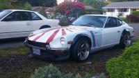
I think this front is very clean looking. If headlight covers would fit that is the front I would go with. Then YZ rear quater panels and you would have a beatiful sports car. Justin
-
I think this is a very good idea. Not only are you gaining shorter intercooler plumbing, but you are reducing total depth through the core by not making air travel first through the intercooler and then through the radiator. I would add a shroud to direct air into the intercooler and make sure it doesn't go through the thinner radiator. Regards, Justin
-
MSII installed running in 78 N/A 280z stock wiring
JustinOlson replied to twoeightythreez's topic in MegaSquirt
Great, Now I have a project for my stinking MS2 that I've never used. Justin -
everyone that has built a custom intake for the L6
JustinOlson replied to turbobluestreak's topic in Nissan L6 Forum
Actually, it may be counter intuative why a protruding velocity stack works the way it does. It actually ends up pulling cleaner air out of the boundry layer around the edge of the plenum which improves performance. I've personally seen good gains by going to a properly designed tappered velocity stack(which in its self helps turn turbulent air from the plenum into nice laminar airflow) that protrudes from the plenum around an inch. The prime example of this are Full-Race/Hypertune inlet manifolds for the supra: