Zmanco
-
Posts
1568 -
Joined
-
Last visited
-
Days Won
1
Content Type
Profiles
Forums
Blogs
Events
Gallery
Downloads
Store
Everything posted by Zmanco
-
Please don't get defensive, but you asked for an opinion on your approach, I told you that I would recommend a different approach and explained why. If you want to try it the way you've proposed, then please by all means do so. As I said in post 8, it may indeed work well enough. Part of the reason I have my Z is that it's a platform for me to try experiments and learn from them. So I encourage you to experiment away! But please don't expect me to tell you what you want to hear - routing noisy high current loads across long lengths of wire is not the best approach - period. That doesn't mean you can't make it work, and if it's important to you for ease of troubleshooting and appearance, then go for it! PS. Even with a larger monitor in my office, I still cannot read the labels on your diagram - I think the resolution of the picture is too low. PPS. I use FIDLE to control the fan as well, but as I said in post 6, I mounted the relay on the radiator tab. The high current wires are on the order of a foot or so in length and only 1 wire goes back to MS. To me, that's a cleaner approach than routing power and ground to it as well.
-
I had never seen that word before, yet instantly I knew what it meant
-
I just told you that this is not the best approach from an electrical point of view. If you want to go ahead and do it because it looks better on a wiring diagram, then go ahead and try it. It may work well enough. I was suggesting an approach that's more likely to give you less electrical noise. You need to choose Form vs. Function.
-
Sorry Jacob80, I'm in a hotel room looking at a small laptop screen and just can't follow your wiring diagram. But you should have a relay controlling the efan which you can mount on the radiator with +12V coming from the alt (with a fuse of course) and ground going to one of the bolts that attach the radiator, so why route that all the way back to your MS? It makes more sense to just route the ground wire that controls the eFan relay back to the MS by itself. Keep in mind that the eFan pulls on the order of 10-20 amps whereas the relay will pull a few tenths of an amp at most. Why would you want to route that much current over a longer distance than is absolutely necessary?
-
On my 73 240Z the headlight switch is on the ground side of the headlight bulb. In other words, the headlight bulbs always see +12V on one of the three terminals, and when the switch is turned on, the path to ground is completed. So with the negative connector of your voltmeter connect to ground, you should be able to see +12V on 1 of the 3 headlight bulb pins at the connector. If you don't then check the fuse box to make sure the fuses are good and the contacts are clean. If you do see +12V, then check the resistance to ground of the other 2 connector with the switch in the "headlight on" position (switching between low and high beam should change which one connects to ground). If the resistance is much more than zero, the problem is either with the headlight combination switch or the low/high beam switch. It could also be with with the wiring, but the switches at nearly 40 years of age are the more likely culprits. On my car the +12V wire is either Red (right side) or Red w/Yellow band (left side). Hope that helps with your 260Z.
-
I don't know what that switch/valve does (my car is a 73 and smog exempt), but I'm pretty sure I have one in a spare thermostat housing I have at home. I'll be back on Saturday and if you still need it, PM me and I'll confirm I can find it.
-
It doesn't matter which wires go to each connector. The sensor is just a piezo electric crystal that outputs a small voltage when it "hears" a knock. The polarity doesn't matter.
-
It's most important that you have a common ground for the small signal devices such as MS and O2 sensors. It's less important for things like eFans. In fact there's an argument to be made that they should be wired separately so that they won't have as much impact on the voltage sensitive devices like MS and O2 sensors when the high-load and noisy devices like eFans turn on and off. But the bigger and better your wires and connections are, the less impact high load devices will have. So it's as much a function of the quality of your wiring as it is how you wire it. That said, I have my MS negative buss (an 8 position terminal IIRC) wired to the negative side of the battery and the plus side wired via a big fuse to the output of the alternator and have not had any electrical noise issues since I switched to Magnecor spark plug wires.
-
Thanks for the cam card S130Z! Interesting that the LSA is 112, not 114. I'm guessing that results in better high rpm breathing (power) with the trade off of less low rpm torque?
-
I know we've left the world of passenger cars driven on the street now ... but I'm curious how the turbo is kept spinning at its optimum speed in the scenario you describe Tony? It seems to me that the ECU would need to maintain some minimum throttle position when the driver lifts off the gas far beyond what we normally know as idle in order for the engine to still expel enough exhaust to keep the turbo spinning.
-
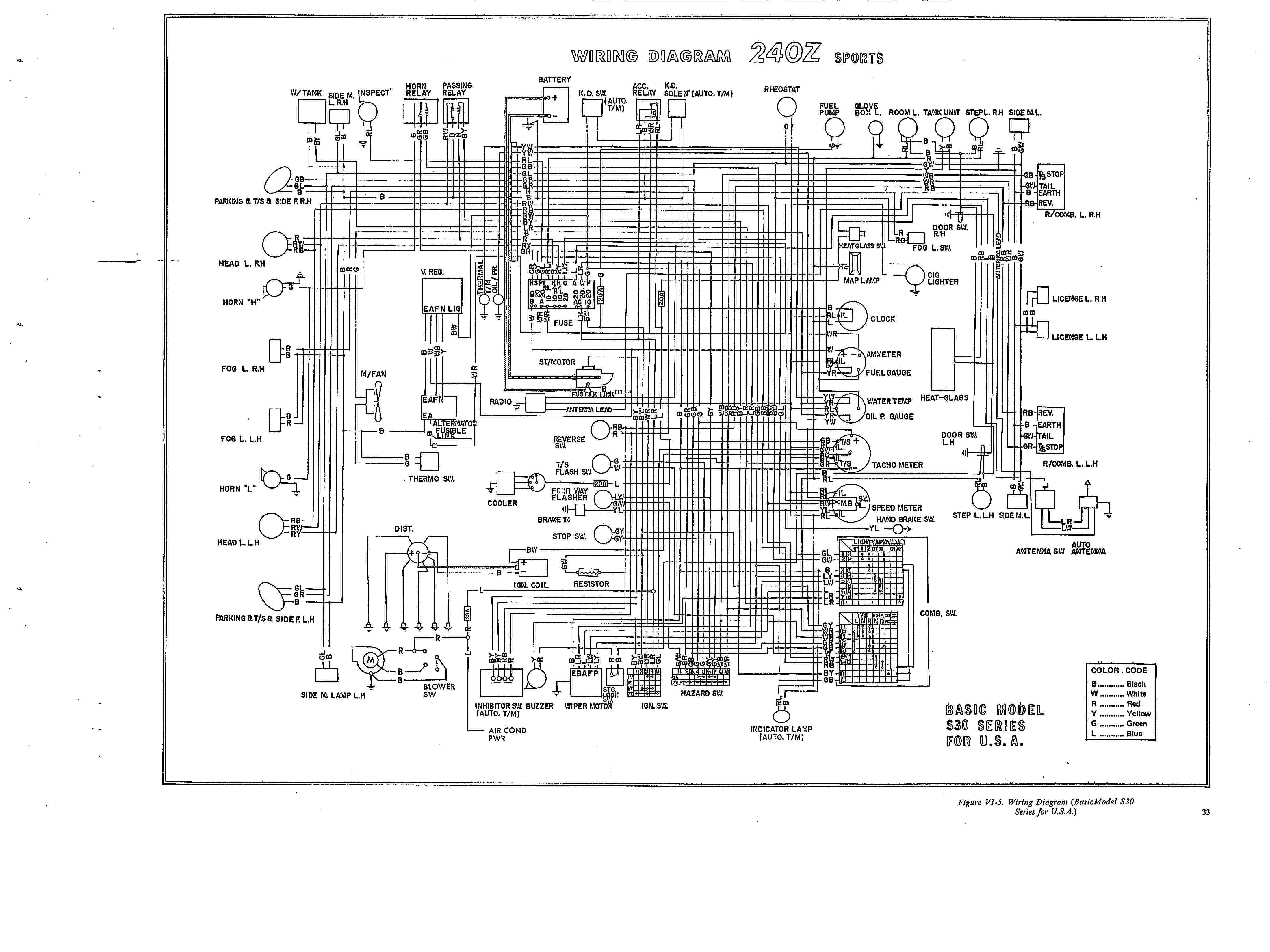
Here's a copy of the wiring diagram for a 73 240Z attached. I don't recall where I found it.

-
The 73 has an inductive (or current triggered) tach and is wired in series (in line) with the supply to the coil. Basically every time the coil fires it is in effect creating a pulse and the more pulses per second, the more the tach needle moves. You should get the wiring diagram for the car - it would have answered your question about how it's connected. These tachs are famous for failing as they are almost 40 years old now. If you can find a known-good one to test with, I'd expect it to solve the problem. I doubt what you're describing has anything to do with wiring. One simple thing to check - pull the tach out and make sure that the needle hasn't come loose and isn't rubbing on the face. It could be as simple as that.
-
You must have a different type than I do. The minimum force to move the actuator correlates to about 8 psi of boost. I can't see inside it but I'm guessing the spring is already compressed. Lengthening the arm just causes the wastegate to leak.
-
Loading the AFR tables is required regardless if you are running O2 correction. MS needs to know how the incoming voltage correlates to the measured AFR and does this with a lookup table. With the ignition (and MS) on but the engine OFF, go to the Tools menu and select Calibrate AFR Table and then choose your controller and the configuration that matches how you have yours set up. I'm guessing that your table is corrupted. Normally you only need to reload the table when you do a firmware upgrade. The table is not stored in the MSQ file, at least not yet - I think Phil is going to add it eventually. A few times after a firmware upgrade I've forgotten to reload it and I've experienced the same symptoms.
-
If it was an external wastegate, then I could change the spring. But it's an internal wastegate with an enclosed (not sure how else to describe it) actuator. The spring is inside it and it's all sealed up. I cannot set it at less than 8 psi unless I change actuators, and I haven't seen any that will fit on a T3/T4 hybrid (needs a bent arm). I'd be thrilled if someone could show me an affordable 4 psi actuator
-
MS controls boost by reducing the pressure applied to the wastegate actuator, thus causing it to open at a higher boost level. It cannot cause the waste gate to open at a lower pressure than the internal spring provides.
-
Have you checked that the stub axles are still in one piece? I had a vibration that turned out to be from stub axle snapping where the splined section ends. I had driven like that for some time
-
You need to tell us what year car before we can help you.
-
I forgot that I'm using the BIP373 coil driver which does shut down when it overheats. Questions: 1. For those of you using a high current coil (I'm using an MSD Blaster) what are you using for max dwell? I was at 3.2 ms, and took a run at 2.0 which didn't seem to make a difference, but wonder if maybe I need to go even shorter? 2. I felt the coil when I came off the track and it was warm like everything else in the engine compartment, but not so hot I couldn't keep my hand on it. Shouldn't the coil be hotter than that if the dwell was long enough to cause the driver to shut down? My instincts say "yes". I feel like I'm fumbling in the dark here, so if anyone has some other thoughts I'd love to hear them.
-
At the track this weekend I was having power dropouts when the day got warmer. My theory right now is that the injector drivers were overheating and shutting down for a few seconds. So I have a few questions: 1) For those of you using a resistor in series with LOW impedance injectors, what value are you using? I have 3 x 6 ohms in parallel with a measured 2.2 ohm resistance. Perhaps this is too low? I can't remember now what led me to choose this value. 2) Can anyone confirm that these FETs behave that way? In other words, does the IRFIZ34N have an over temp protection mechanism? The datasheet doesn't say anything that I could find that says it has this feature. 3) Here's a thread I have going on the megasquirt site that so far hasn't yielded anything substantial. Can anyone suggest an alternate theory for why I'm seeing the power dropouts? One problem with my theory is that the power drops completely which would mean that both drivers would need to shut down and then resume simultaneously, something that seems improbable to me. 4) Could it be the ignition coil driver overheating instead? I tried reducing dwell to only 2ms and it didn't make any difference. The VB921 datasheet doesn't say anything about overtemp protection either. This is a really hard one in that I can't reproduce it on the street. The nearest track is 80 miles each way with limited availability and costs $90 per half day. I really need to work this out "on the bench".
-
I had the car out on a road course this weekend and what felt too sensitive on the street was just right on the track. I suspect it was because most corners on this track are 3rd gear with entry speeds between 50 and 70 mph, so even full boost (8 psi) wasn't affecting the chassis balance too much. There was one 2nd gear corner hairpin at the top of a crest and I had to be careful to avoid wheel spin accelerating out.
-
John, forgive me if this is a stupid question, but that cam doesn't look eccentric. How would it help?
-
I just can't resist: I'll add some more thoughts based on my experience with an S30: - 300 HP from a turbo L28 is still reasonably streetable and reliable, although the power delivery on boost is tough to modulate - I don't think 400 HP would qualify as streetable or very reliable for a DD. - The more you modify the suspension to improve track performance, the less fun it's going to become as a DD. I don't know how an S30 compares in this regard to an S13, but I'd guess that the S30 would need more agressive mods so perhaps a well set up S13 would be easier on the street? I don't know this - perhaps others can chime in here. I'm not a huge fan of the 2+2 due to the extra weight, but I suspect that a warmed-over (engine and suspension) 2+2 would be pretty unique just about anywhere you went. You'd surprise a lot of people on the track I'm sure.
-
I had the dealer-installed AC in my 73 and even when refilled with R12 it was nothing like a modern car. It was barely adequate at highway speeds, but pretty much useless in stop/go driving. I have not tried the Nostalgic Air, but I have a friend who put a Vintage Air http://www.vintageair.com/ into his 73 and says it blows ice cold.
-
LOL, I've got a track day tomorrow which will be the first event with new Techno Toy Tuning front LCA and TC pieces and the extra camber and caster they bring up front. Frankly I'm a little nervous because I expect to have more FRONT grip than I'm used to, as well as more power that's difficult to modulate and can overwhelm rear grip. That could be a recipe for less-than-graceful cornering. I'll know a lot more in 24 hours.