Z Greek
-
Posts
110 -
Joined
-
Last visited
Content Type
Profiles
Forums
Blogs
Events
Gallery
Downloads
Store
Everything posted by Z Greek
-
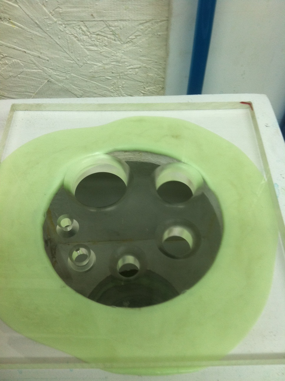
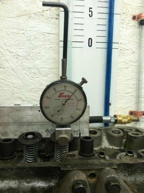
Here are some pictures of the bench, manometer, calibration plate, valve opener, etc.

-
https://docs.google.com/open?id=0BzPD5idjMQ5BYlFLOHNpUEw4WWM Per loy's suggestion above, here is a link to the flow data on the P79 vs P90 I did today My 14 year-old did this for me, hopefully it works!
-
Well I thought I had some fun stuff to share, but the site will not allow me to attach an excel spreadsheet, and if I try typing the data in manually, it bunches it all up. The long and short of it, the stock P79 flows just as good as the P90 (on my budget flow bench). The big difference, you can change the P90 port. Short of cleaning up the transition from the seat to the liner on P79, you are pretty much stuck the way it is. I have a P79 on my Chumpcar endurance racer that I spent a ton of time on. I am getting ready to take it out of the car and will flow it when I tear the engine down. It will be interesting whether I went forwards or backwards! The Chump L28 made 178 to the wheels on a dynojet 24 last summer. The engine now has 45 hours of racing on it. I am going to try to get it on the dyno one more time before I tear it apart to see how 45 hours of pretty intense use affected it.
-
Well that did not work, hang tight!
-
I built a budget flow bench a couple of months ago. I have spent the time since I built it refining, and calibrating. I built it per a design from a book by David Vizard, and had a calibration plate machined out of lexan per a design by a friend of Vizard's, Dr. Helgesen. I say all this because although this bench was built on a budget, it is pretty accurate, especially if one is just comparing before and after, or one head to another. Initially I was having trouble getting repeatability, and traced the problem to varying line voltage in my shop. I have since run a separate, designated 20 amp circuit using over-sized wire to minimize voltage drop to my air source (two 6 hp shop vac's!) So I finally have the bench working well enough to achieve repeatable results. I also pieced together a fixture for opening the valve incrementally. I have a P90, and also a P79 in completely stock, unmolested condition. I flowed the P90 first, doing the intake first, and then the exhaust. While flowing the intake, I had an N36 manifold bolted to it. The exhaust was left open at the port. I realize not having a stub exhaust pipe bolted to the head affects flow, but I did the P90, and the P79 the same, so I think any error should equalize between the two tests. Most everyone I talk to, or read about praises the superiority of the P90 exhaust port, and how "evil" the P79 port is with the liners. Well gents, look at the results below. Not only did the stock P79 flow as well as the P90, it was virtually identical. I did not flow the P79 intake yet, but since the P79 and P90 are identical on the intake side, I do not expect any surprises. P79 VS P90 flow characteristics Home-built floating depression flow bench. Calibrated with Helgesen Plate. P90 Intake P90 Exhaust P79 Exhaust Valve open increment Inches of H2O CFM Inches of H20 CFM Inches of H2O CFM 0.05 44 30 18.2 18 18 20 0.1 40.7 60 16.9 50 16.8 40 0.15 37 105 15.8 71 15.8 70 0.2 32.2 148 15 86 15 85 0.25 30 180 14.5 94 14.5 95 0.3 28.5 200 14.3 97 14.3 98 0.35 31 165 14.2 100 14.2 100 0.4 31 165 14.2 100 14 105 0.45 30.8 170 14.2 100 14 105 0.5 30.2 175 14.2 100 14 105 0.55 30 180 14.2 100 14 105 0.6 29.5 185 14.2 100 13.9 108
-
I have bought several N42's at our local pull and save yard for $150 for complete engine. Around 6-8 Z's seem to filter through each year. There is one out there right now, I just don't feel like crawling around in the rain to pull it, and it will be snow soon!
-
-
Looks like the head I just finished porting by hand.........ya right!
-
Wow, That's pretty dramatic. I run a WELDED R180 4.11:1 in an endurance car (Chumpcar), and it is very predictable. Oversteer can be induced very easily with throttle, but I have not noticed the violent off throttle oversteer your car seems to exhibit. The car has about 40 race hours on it, but we have not run it in the rain. I have spun the car a couple of times, but it was a combination of off throttle, and too abrupt braking (my fault, rookie mistake). What tires are those? Were other cars spinning? Personally, I would not be so quick to blame it on the diff., but others may have a different opinion. I plan on using a Subie VLSD in my street car.
-

Spindle-Pin-Puller Loaner program
Z Greek replied to Dave's topic in Brakes, Wheels, Suspension, and Chassis
Any of these left? I would hate to miss out if this is truly the last batch! I'll send you a paypal right away if you still have one. Thanks, Andy K -
Started my engine build (First ever engine build)
Z Greek replied to Ben's Z's topic in Nissan L6 Forum
How's it going Ben? Did you get the shortblock put together? -
Started my engine build (First ever engine build)
Z Greek replied to Ben's Z's topic in Nissan L6 Forum
I just looked at your photo's above. I was not able to expand them last night, the telegraph wires must have been a little finicky last night up here in the inland NW, we barely have indoor plumbing, much less high speed internet! The bearing shell hanging beyond the width of the cap is NOT RIGHT! Take all of the caps back off and find out where you have them mixed up. Not what you want to hear, but you are only talking about 30 minutes. Remember, if something does not seem right, stop, investigate, and rectify! -
Started my engine build (First ever engine build)
Z Greek replied to Ben's Z's topic in Nissan L6 Forum
I put them in carb dip and used an old ring to clean the grooves along with a plastic brush from my gun cleaning kit. Be really careful with an old ring, it is really easy to damage the land surface with a sharp object. I know it sounds like I am harping on this, but it is really important. You can have the best ring seal in the world on the bore surface, but if the ring does not also seal against the ring land, a portion of that gas you are trying so hard to trap in the combustion chamber finds a way out past the ring/ring land interface, and down into the crankcase. It is not like the engine won't run, but with the time and effort you are putting in, you want it to be as perfect as possible! Good luck. (I know what you meant about the "megasquirt" quip, hardly anyone ever responds to my posts either. Sometimes it's best to keep comments like that to yourself though, so as not to stir up the natives!) -
Started my engine build (First ever engine build)
Z Greek replied to Ben's Z's topic in Nissan L6 Forum
If you promise not to call me a dickbag, I'll chime in a bit. I am not a professional engine builder, but a dedicated hobbyist, a lifelong car nut, and someone who has gotten to know and appreciate the L6 engine over the last year or so. I have built three L28's this year, and have learned a thing or two along the way. I have assembled dozens of automotive engines, but only BUILT a few. If you get serious about this engine thing, you will find out what I mean. 1. Regarding the question of different bearing widths, there ARE different widths, but it is very obvious where they go. The width of the bearing shell matches the width of the cap/main saddle. In regards to your main seal question, it must be square with the face of the main cap/main saddle. There is no "step," as was previously mentioned in this post. You must drive it in square. Some prefer to place the seal on the crankshaft before lowering it into the bearings. I have tried this, and did not like it, but I can see how it would work OK. Regarding the rubber pieces along the side of the rear main cap. I put a DAB of silicone on the bottom of of the rubber, and then slide them in as far as they will go. There will be about a quarter inch still sticking out, trim that off with a single edged razor blade. Now carefully drive the nails (or flat metal pieces, depending on the make of the seal)flush with the pan gasket surface. I am not trying to patronize you, but here is something to pay attention to. For each pair of main bearing shells, only one has a hole in it. the one with the hole MUST go in the saddle in the block. If you put the shell without the hole in the block, the engine will fail instantly. This mistake has been made more than once. Here are a few "laws" of engine assembly I pay particular attention to. 1. Cleanliness is next to godliness. Clean everything until you could either eat off of it, or eat with it, and keep it that way. Seriously. 2. When installing bearing shells, make sure the back side of the shell, and its mating surface is ABSOLUTELY CLEAN. Secondary job of the bearing is to dissipate heat into the mass of the block. Never put oil, or any other foreign substance between the bearing shell and its mating surface, especially not locktite, as I have once heard recommended! 3. If you ever question anything, stop, investigate, and rectify. (like you are doing now!) 4. Check the engine for free revolution each time you add a piece. The crank by itself should spin VERY freely. If you have everything right, the crank should actually continue rotating for at least part of a rotation after given a quick "crank" with a ratchet on the snout of the crank. As you add pistons, there will be ring drag. Ring drag is harder to judge, but engine should still rotate very smoothly as you add pistons. You will get a feel for it. 4.5 Speaking of pistons, check ring gap on every piston. Better to have a little too much than too little. If you do end up filing the end gaps, be very careful to keep the end gaps square. Also, pay very close attention to the ring land which the side of the ring rides against. This is a sealing surface. If you are using used pistons, and need to clean the ring grooves, be very careful not to nick or damage this surface. Ring seal is as dependent on this surface as it is the bore of the block! 5. Pick the machine shop with the best reputation in your area, and then re-check every dimension. You mentioned plastigage in your introduction to this post. Plastigage is better than nothing, but is a little like measuring with one of those wooden rulers we had in grade school as kids. Better than nothing, but not very accurate (my opinion). If you are serious about engine building, start investing in some precision measuring tools. Start with some micrometers, and some snap gauges for inside measurements. It takes practice, but soon you will be making accurate, repeatable measurements. I recently graduated from snap gauges, to a dial bore gauge, which is a wonderful tool! I received some great L6 specific advice from Peter at PMC Race Engines that was a huge help in my early quest for L6 power, Peter is a master of these engines, and a gentlemen as far as answering questions, if you ask nice!. I would also recommend setting cam timing, even if you are running a stock cam. If it is a stock cam without a cam card, I have had good luck setting it at split overlap (both valves open the same amount at overlap). This is actually how Rebello recommends timing the cams they sell, as they do not supply cam cards. Have fun, good luck, and hope you find some horsepower! -
Why did you decide to stay with the Datsun L6 motor?
Z Greek replied to logan1's topic in Nissan L6 Forum
First of all, I am a bit old school. That being said, I have grown to appreciate the wonderful design of the L-series engines. I am building a street car with a 3.1 stroker (which the long block is finished on the stand), but have been bitten by the racing bug, and have had a blast building a couple of budget L28 endurance engines. The last one is bone stock, runs SU's and made 178HP to the Wheels on a brand new Dynojet 24. The car that engine is in weighs 2,150 with a full tank of fuel, and is a kick in the ass to drive. These engines are brilliantly designed, tough as nails, and BELONG in our cars! And that is all I have to say about that. -
DOHC L6, Was somebody looking for the Goerz-Paeco DOHC L6 Head ?
Z Greek replied to Vintageracecar's topic in Nissan L6 Forum
Sparkin' bolt holes do look conspicuously absent. -
Don't do it, your transmission will get confused and start trying to shift by itself!
-
Very nice Peter, look forward to dyno numbers.
-
Great point, thanks for pointing this out.
-
I bought a 2 row Champion for my Chumpcar, but I have not tried it out yet. The construction looks very good. I went with 2 row due to the large size of the tubes. Currently we are running a stock rad (I would have to look, but I am pretty sure it is a 3 row) from a later model 280. The engine in the Chumper is a 2.8 that made 178whp on a new Dynojet 24, so I don't have near the waste heat that you do with your godzilla stroker turbo, but we do run in 100 degree eastern Washington heat for 24 hours at a time, and water temp stays rock solid at 190.
-
They are 6 x 1.0 x about 30mm in length.
-
It will absolutely leak if one stud is not used (any of them) sorry to be a downer, but it must be fixed.
-
Ahhh, I did not realize you were running a turbo. I have had very good luck with the felpro head gasket in my endurance N/A engine. Pretty modest output, but we torture these things for 24 hours at a time. I made sure the block and head were both dead ass straight, felpro headgasket, and used arp studs torqued to 60 ft lbs, set over night, and then relaxed, and torqued again. A good buddy of mine who builds endurance jet boat engines taught me that technique, and it has served me well. I am sure some of the other turbo guys can chime in and share their experience. Good luck!
-
Out of curiosity, why do you feel you need a metal head gasket?
-
Should be a beast, Peter. Can't wait to see dyno numbers!