

turbobluestreak
-
Posts
448 -
Joined
-
Last visited
Content Type
Profiles
Forums
Blogs
Events
Gallery
Downloads
Store
Everything posted by turbobluestreak
-
-
-
loud pop now only 10 psi of boost?? need help
turbobluestreak posted a topic in Turbo / Supercharger
I've got a problem. I've just installed a stage III turbine wheel in my t3/t4 turbo to solve my topend chock up. Well it was boosting fine 19-20psi and then just like that a loud pop and only like 10psi max. I don't belive that I have a leak but I'm not 100% for sure but it really sux. I do maintain a perfect idle with 19.5 in of vacume. tbs -
I believe that 81 280zxt came auto only. tbs
-
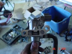 looks like an idle speed control device like that used on the 1G and 2G DSM's but I'm not sure though because this is nissan and not a mitsubishi.tbs
 -
On the GM typhoon there is a mitsu/garret hybrid 17c also 20g hybrids can be ordered for the typhoon as well. tbs
-
yah I torqued my head down right but I'm just worried that something is wrong. tbs
-
ok two weeks ago I blew an Nissan head gasket so I decided that I would upgrade to the hks steel head gasket. I had the head checked and said it was fine. So I installed it dry and torque it down to 55ft-lbs with oil on my arp studs. my problem is that when I start my z up i now see water come out my tail pipe which did not happen before I blew my gasket. So is my gasket not sealing correctly or WTF? Also as I remember my surface finish on the head wasn't the greatest but I've never used a metal head gasket and thought it would be fine. So now that read all the post that I could find here on hybrid and zcar after I installed it. Yah dumb move on my part I'm thinking I screwed up my install what do you guys think should I pull the head?? tbs
-
24 Valve DOHC head almost done!
turbobluestreak replied to turbobluestreak's topic in Fabrication / Welding
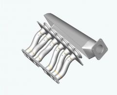
Nope. I haven't worked on it in a long time. I have been concentrating my efforts on getting my z ready for this year. But a little off topic my custom intake is done and will get some pics up on here soon. tbs -
Are the studs on located on one side or on oppiste sides?? Well the right thing to do is Legal Action but if you are hell bent on saving this block which I can under stand. I would hunt for a welder with a large oven and get him to out the bad areas out and weld them together and then bring the block back down to temp in the oven. My instructor at the college used to work for GM in a pattern shop and knows all about welding cast iron so if you need to know what rod to you I'll ask him. If you do this I'll send you the print dimensions for the head bolt pattern to get them back in alingment. I only wish you were closer, then I would just give you a block. tbs
-
I'ld weld it like I'm doing. Two bolts arn't going to do anything for holding the head together. I'ld like to know what crank gear you have on that? I've tried boring out a stock KA24de gear and it broke at 300ft and the key (thats supposed to fail) was still holding up. tbs
-
all emissions can be taken off. I know I did. Also get rid of that pop off valve and replace it with a 1inch pipe plug and take it out for a spin. tbs
-
franky, if you do a search on here for the DOHC under my name. You'll find that the suggestions of epoxy and welding. But one way was to mill extra off each piece and then lay up a .040-inch bead of weld on each side that butts and then mill it back into spec. Next build a jig to hold it and send it out to be laser welded it's about 40 bucks a seam. I wish I would have decided to do this but it's to late for that now. This way its perfectly sealed and then just stress relief the welds and your head will be solid. tbs
-
Yah my favorite L6 subject KA DOHC. Your head looks great I would like to talk to you about your lower timing setup that you have on that. What kind of valve to cylinder wall clearance do you see? I've been concerned with that issue since these heads operate on a 89mm bore? Now to the real issue welding the head I would get two cam blanks made up that will cause a slight interference fit, bolt them down tight. Make plates two of them to hold the sides in alignment. Next the bottom surface should be made from 1-1.5 inch thick steal plate that is ground flat and ream two head holes per chunk for locators. I you want a print of the spacing of the boltholes and bore spacing I'll send it to you. Lastly, it just wouldn't be a true DOHC L6 post if I didn't chime in. LOL Good luck and let me know if there is anything I can do you help out. tbs
-
Not to burst your bubble but casting is exspensive and why would you want to allow for the chance of casting inperfections when you could make a sheet metal intake that will be all smooth? tbs
-
Sorry I thought that was yours HS30-H. Could anyone tell me more on how the S20 is timed? Does anyone make performance cams for the S20? I think I'm going to need a set for my custom 24valve head because the S20 valve train resembles what I've got coming together from the two KA24DE heads.
-
I just saw your gallery on classic zcar club and I had no idea that the white z was your z, I've seen pictures of that before and it's breath taking. tbs
-
But p79's have exhaust liners kill flow. That’s why everyone wants p90 or n42 and in reality yes p90 will lower quench but if you raise the compression you will have a more efficient motor. Efficient motors make more power and take more advantage of existing and future mods. tbs
-
I purchased these seals and right now I'm not to sure letting some one else install them when I get my valves done. So I've got a ford valve guide on order and will see how these things go on the right style of guide. I plan on machining what ever ford has on there guide into my new z guides to insure proper seating. Just my 2 cents. tbs
-
so what kind of flow numbers do you get from each stage? tbs
-
Z31/300zx ECU/MAF to 280ZXT swap guide
turbobluestreak replied to Afshin's topic in Turbo/Supercharger
would the stock non turbo dropping resister have enough resistance to bring the voltage down? Also are we talking about going from 12volts to 6 volts? tbs -
spacers should be 1/2 inch thick and you'll need to grind away a little off the manifold or make the spacer about 6/8 thick. also you'll need longer studs for the turbo. However this can all be avoided if you swap back on your OEM turbo exhaust .63 a/r housing and grind a little off the manifold. tbs
-
What's the rod length going to be. tbs
-
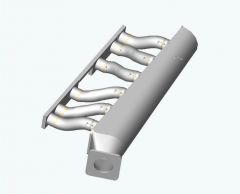
I haven't really be working on any heads latly. I've been so concered with trying to get little things done in the shop and still keep my grades up. Guys I need to know if this sounds right, i've read once the onset of boost the runner length no longer matters. If is true then I can go with my first design for turbo engines which makes my life so much easier but for non turbo I'm working on one that will take advantage of midrage to top end with a 248 cam. I understand that this cam is small but thats what I have in my turbo z and basied everything off of my engine so far. So I belive I'm all set to go with the first intake that I posted for my turbo car. If anyone is intersted I'll take the time to help you out in designing an intake to fit you needs. tbs
-
Phyxius it's around 3inches in the head I'll cc it soon and let you know the volume later. Right now I'm trying to detrmin what rpm to tune the intake in at I'm thinking around 4500rpm with my 248* cam. if thats true then the intake runners will be around 12 inches . Space is limited and I need to refigure the confinements of the engine bay. Phyxius I'll iges my Velocity stack and have you run a CFD on it before I start machining them. tbs