
Top Fuel ZX
-
Posts
48 -
Joined
-
Last visited
Content Type
Profiles
Forums
Blogs
Events
Gallery
Downloads
Store
Everything posted by Top Fuel ZX
-

Calling All LT1 Conversions
Top Fuel ZX replied to Danno74Z's topic in Gen I & II Chevy V8 Tech Board
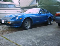
Minus the emission equipment, I got a bone stock 94 Pontiac TransAm LT1 in my 81 280ZX. Engine probably has 110K on it. It's my daily driver and I've put over 10K miles since the conversion. Car has the following: * Stock suspension * R230 differential * 4L60e tranny * Dual 2.5" going into a single 3" exhaust and a 40 series Flowmaster by the gas tank. * Don't laugh but I got a stock manifold on the driver side and a block hugger header on the passenger side. Clearance issues. Haven't had a problem yet. * MSD fuel pump. Fairly loud by the way. 1/4 mile: 13.10 @ 106 Pics in my album. It's a fun little sleeper Sean -
Great find! I just bought some muffler bearings from KalecoAuto. I hope that eliminates the noise coming from my exhaust. Sean
-
 Just to give you an idea of the sound...Dual 2.5" exhaust going into a single 3" out the back. No cats...Running one 3" Flowmaster 40 series muffler. So it's kindof loud
 -
And it was awesome I got the jump on him at the start but he overtook me 2/3 of the way down the track. All I can say is that car is fast!! 617hp!! The guy was kindof snobbish. Oh well. The only thing I could beat him at was the r/t and 60 foot time. Sean
-
Nice job...Now bring some sunshine up here so I can wash my car...haha..That's a nice paint job! I can almost tell the brand of camera you have just from the reflection off the water temp. Sean
-

-
 I got OWNED!!! by a SLR....and it was awesome
 -
Here's what I used to align the diff + tranny and measure the angles. I've been running my setup for over 1200miles....no vibrations. http://forums.hybridz.org/showthread.php?t=109413 Sean
-
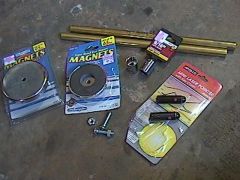
Alignment Tool Here’s info on how to make a Differential Laser Alignment Tool. This tool allows the user to verify that the differential and transmission are in phase. I have used this on my 81 280ZX(LT1/4l60E with R230) and have had no driveline vibrations. I am posting this info because there have been questions regarding how to align your diff with your tranny. This is a good alternative to the other options. Special Note This is Pop N Wood’s idea. He thought of the idea of using lasers and everything. All credit should go to him. This is NOT my write-up for building the alignment tool. I can’t find the originator and his website is long gone. I merely had a saved copy of his write-up on my computer. Additionally, the Hybrid Z thread discussing this stuff was deleted years ago due to the server changes. -------------------------------------------- Parts Required 2) 1/4" x 1" tapered head machine screws and nuts (I used 1.25" long screws and shortened them because that's just what was on hand) 2) 9/16" 'ACE' hardware branded sockets, 3/8" drive, 12 point (only use 12 point. other brands may work, but the tolerances may also be different enough that the fit will not be secure or too tight) $2.50 each 2) Model #MP600, Apollo brand laser pointers from office depot. $10 each 1) length of 9/16" brass tube from ACE $2.50 1) length of 19/32" brass tube from ACE $2.50 1) 3.2" diameter lifting magnet [The Magnet Source, model 07223] from ACE (particular magnet for your transmission application may differ. This particular model has a 1.20" diameter hole in the middle of the magnet, which allows the output shaft to fit inside enough for the flat end to seat against the metal shell of the magnet. other applications may need a smaller center hole so the magnet face seats on the output shaft, or a larger hole for a larger shaft. Alternatively, as long as the transmission you will be using does not have some change of output angle built into as some do, you can select a magnet that will fit firmly on the back of your engine's crank.) $7 1) 2 5/8" diameter lifting magnet [The Magnet Source, model 07222] from ACE $5.50 Below is a picture of all the parts required Attaching 9/16†Socket to the 2 5/8†Magnet Place one of the sockets on the top of the 2 5/8" magnet shell with the ratchet attachment side down. pass one of the machine screws down through the socket and into the small hole in the magnet shell. Thread one of the nuts down on the other side of the magnet and tighten. The tapered head of the screw should automatically center the socket on the magnet. Example pics show a 1.25" machine screw that has been ground down on the threaded end. A 1" machine screw should not require this, but be sure to check that the magnet seats firmly and that the screw is not high-centering the device against the input flange's nut. If the screws are ground down to perfect length, be sure to tread down one of the nuts past where it will be cut/ground so it can be backed off to realign the threads when done. Assemble Tools Read entire step before proceeding Step 1 Cut a 1.25" length of each end of each of the pieces of brass tubing. You will want the nice flat manufacturer's end of the tubes to be unmolested so they can seat firmly and evenly down in the socket. These two pieces will nest inside each other nicely, but given the short length of the tube that will actually be used, you may find a slight amount of play. In the z car, the short driveshaft length makes angular accuracy critical, so I felt I needed to address this nearly imperceptible tolerance. Your particular tubes may fit more snuggly than mine depending on manufacturer and such. If needed, some silicone gasket sealer or epoxy could be worked inside the 19/32" tube, left to sit for about 5 minutes and then insert the 9/16" tube. If you are going to do this operation, do so before making the 1.25" cuts. With the full length of the tubes nested together, there will be almost 0 angular movement, and this is the best environment in which to allow the gasket sealer or epoxy to set up. I used 'plastic welder' epoxy that has a set time of about 15 minutes and remains slightly pliable after setup so it wouldn’t fracture while I am cutting the tubing. I only applied it inside the last two inches of each end of the 19/32" and then fed the smaller tube inside. most of the epoxy will be pushed out, but that should be okay since only a fine film is necessary to close the gap. While the epoxy or silicone is setting, move on to the transmission side. Step 2 For the transmission end, my ford t-5 has a centered machined depression in its output shaft that could be used for centering the magnet with its protruding screw, except that the shaft sits in the inner diameter of the magnet, so the inside part of the metal shell needs to remain flat. What I decided to do here is screw the socket in the same manner as the differential unit and then place four tack welds around the base of the socket, then removed the screw and nut. You could alternatively use epoxy (jb weld) in substitution, just make sure the screw stays unglued so you can later free it once the epoxy has set...and take care to evenly sand the metal magnet 'skin' to give the epoxy something to set into while making sure the 'skin' surface stays flat and true. take care that the metal shell of the magnet does not warp from welding heat. use the lowest temp necessary. I placed my ground clamp on the socket, to keep the current path as far from the magnet itself, just incase that might have caused a problem. be careful to make sure the glue holding the under side magnet is not preventing the output shaft from seating evenly. It could probably be ground down with a dremel if it is. Hopefully the brass tubes are ready to be cut by now. Step 3 As stated before, cut 1.25" of each end of the tubes. be sure to use very fine blades. I'd suggest doing it by hand to be safe to make sure they don't deform. clean up the cut ends of the short pieces so they aren't jagged. The lasers have rubber buttons, and could be snagged and torn if the tubes aren't smooth. use some fine sandpaper for this. Be sure there are no burrs or excess globs of glue or silicone inside the tubes because they will be very difficult to extract later. Step 4 Carefully fit the pieces of each nested tube assembly into each socket. Some pressure may be needed because it is a very snug fit. be sure to apply pressure perpendicular to the face of the magnet. using a vice or press may be a good idea too. Step 5 Insert each laser into each magnet/brass tube/socket assembly. Sanding the paint off the laser may be necessary to fit it in the tube. Sand up and down the length of the laser to make it easier to slide in. To turn on the laser, simply push it down in the tube far enough to push the red button in [Addition: When you push the button into the tube, this will cause the laser to not be perfectly centered….Meaning if you rotate the magnet, the laser beam will follow a circular path instead of being perfectly stationary]. To turn it off, pull it out of the tube slightly. Optionally, you could pull the button off, drill a hole through the side of the tube and insert a rubber plug or something through the hole into the laser switch area and use a hose clamp to put pressure on the rubber plug. Using the Tool Now, make sure the laser assembly is accurate. place each one on the nose of a differential and turn it by hand, taking note of the path the dot takes against a wall or other flat surface. The greater the distance between the laser and the flat surface, the easier it will be to true of course. you can shim in a number of ways to get the laser true...placing slivers of aluminum soda cans, sheet metal, paper, or tape between the magnet and the surface, bending the laser and tube slightly, or placing paper or tape under the socket and re-securing the socket against the magnet. Continue to shim and test until the laser's dot does not trace a circle against the test surface. This entire calibration could be avoided though if you simply hang a sheet of paper in front of the transmission output shaft and trace the path of the dot to find the center while both are in the car. The same can be done at the diff. However, if the lasers are trued, you can use steam, dust, or a fog machine to very easily determine if the lines from the transmission and the diff are parallel in both dimensions just by eyeing them and moving the drivetrain components around. If a smoky substance is not available, you can insert a piece of paper at different points along the two beams and see if they stay equidistant or not and adjust as necessary. Addition To obtain the angle of the tranny compared with the differential: Arc tan(Distance between the two laser beams divided by the distance between the output shaft of the tranny and the input flange of the differential) Enjoy, Sean
-
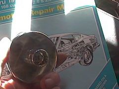
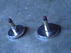 Shown is both alignment tools...the larger magnet goes on the output flange of the tranny and the smaller magnet goes on the input flange of the differential.
 -
-
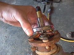 The smaller magnet alignment tool is placed on the differential and the larger magnet goes on the tranny
 -
 This photo is the underside of the smaller magnet. Notice that the bolt protrudes beyond the magnet.
 -
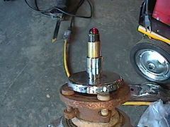
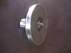
 This is a partly assembled laser alignment tool that I used when puting in the LT1/4l60E and the R230. This photo is the smaller magnet and the socket gets bolted to the magnet. The larger magnet has the socket epoxied or welded to it.
 -
-
80LT1- I can't wait to see what your car gonna run down the track. Eventually I'll build an LT1 motor similar to what you've got now. You're probably right about the slicks. I still think I could get a better 60' time. But I was only able to get two runs in Sunday (raceway was packed with cars due to the sunny weather). Sean
-
Currently I'm running a 3.69:1 R230 from a 300zxtt...So 80LT1, when is your car gonna be back on the road? Looks like your 280ZX is gonna be a import killer Z-Gad- Your right. It feels awesome getting my car back to the track. Now all I think about is what else I can do to go faster. Maybe I'll buy another LT1 and build it from the ground up. And do a quick swap of engines to keep the car on the road for as long as possible. Prior to my swap I was running a bone stock 81 280ZX n/a. Ran the quarter mile in 17.36 Sean
-
Made a couple of runs today in my 81 280ZX LT1 4l60e w/ R230 diff. I'm the one in the left lane. Ran a 13.309 That was my best time at the track today. Not too bad for a stock 94 trans am motor. Didn't have any traction issues to speak of. And that was with street tires and stock wheels (215/60r14) Only real problem is I think I'm hitting the rev limiter because the engine studders between gears. The best part is when people ask me what motor I got because they know the car's been modified. I jokingly reply, "what are you talkin about...suckers bone stock:)) All in all, it was a fun day. Sean
-
-
Similar to what Z-Tard said but you can tell if it's a LSD by turning the input shaft of the differential. Both output shafts will rotate together in the same direction. If its an open differential the output shafts will rotate in different directions. Sean
-
OK...So Who Wants To Buy A Brand New S20 Engine...PicS!!
Top Fuel ZX replied to slownrusty's topic in Non Tech Board
To each his own. If I had the money, I'd take the LS7. But the S20 would be pretty sweet to put in a Z. Cars that appeal to me are ones that are different and/or modified. I would respect anybody who had the balls to modify a car beyond stock (cold air intake and cat-back exhaust doesn't count). Why are we all here on hybridz.org? Isn't it because we all share the disease of modifying cars. Specifically, zcars? This site was founded on that belief. Other zcar forums might reject our ideas as EZ-E mentioned. Two years ago, I told a fellow Zer that I plan to put a v8 in a 280zx. He responded by saying, "now why on earth would you want to do a thing like that?" I've also been told that putting a LT1 in a zcar is "a waste of a chevy engine." Honestly, that's their opinion and not mine. Sean -
NOTE: [highlight]Part #3102-42[/highlight] is for the 300zxtt R230 (flange mounts to diff with 6 bolts) . To my knowledge, the Q45 R200 mounts the flange with four bolts. The Powertrain Industries part number for this is [highlight]Part# 3102-69[/highlight]. SOMEONE SHOULD VERIFY THIS THOUGH. Sean:)
-
I believe that is a driveshaft flange built by Powertrain Industries. I have noticed they are the only company who makes a u-joint conversion for the R230's input flange off of a 300zxtt. They also make a flange for the Q45 R230 as well. http://www.driveshaft.com/catalogs_type.htm?type=Flange%20Yokes And yes I did need it...very badly too So what did i win? haha Sean
-
Constantly getting looks, comments, honks.
Top Fuel ZX replied to BrandonsZ's topic in Non Tech Board
I feel your guy's pain...haha....My 81 280ZX gets looks from people of all ages. Just last week i drove past a group of kids and one of them yells out, "Nice car!" Also, yesterday I was showing the car to my coworkers and an older gentlemen was walking by, takes a look at the engine bay, turns around and was like "Is that a v8? Nice." If only I could drive my Z more often... Sean -
Took picture a couple years ago before conversion...still looks the same.