

JMortensen
-
Posts
13742 -
Joined
-
Last visited
-
Days Won
68
Content Type
Profiles
Forums
Blogs
Events
Gallery
Downloads
Store
Everything posted by JMortensen
-
 The area of stronger, reinforced metal where the bearing holders are attached to my early Z car is actually very small. It only extends maybe 1" on each side beyond the area where I've welded in the bearing holders on the bottom, and then it also attaches to the reinforced area in the trans tunnel as well. To the sides of the bearing holders the frame rail changes, and goes from .108" thick to .035" thick (guessing on the thinner stuff, but it is sheet metal thin). This small area of the chassis isn't only subjected to side loads, it also handles all of the upwards torque from the nose of the diff as it tries to lift. I have an alternate diff mount, but it still puts that torque into the chassis through the diff crossmember, and that means directly through the bearing holders. I suppose I could have done the Ron Tyler diff mount, but I've already put a lot of time/effort into the one I made previously, and don't just want to switch it out now. The point is, there really is a lot of upwards stress on the chassis right there. What I'm really worried about though is the fact that with NO rubber in the suspension there will be NO damping of any shock loads going into the chassis. That's why I'd like to make this area as stronger. I've already redesigned the uprights in the back to make them stronger, and the footprint of the uprights is probably 300% larger than the original design, so I'm hoping that will keep things intact in the back. I would like to do something to prevent damage in the front here as well. If the supports from the main hoop were straight up and down, that would mean that they would not be terribly good at dealing with side loads. They're not, though, and by coming in at a 45 or so degree angle they should be able to handle some side loading with too much trouble. For these braces I'm going to use 1.625 x .065 tube, which is about 1.1 lb/ft. So while I will be adding weight, and I'm trying to figure out the most efficient use of that weight, it won't be as bad as the main cage structure which is 2 lbs/ft. Lastly, I do think there is some value to adding more support back here. I'm going to be running some extremely heavy spring rates, taking a cue from those wackos down in Oregon... They seem to be having really good luck with spring rates over 500 in/lbs, so I'm expecting that I'll probably start out somewhere in that range. Not to mention I'll be on very wide slicks. If I use the previous slicks I was using, they're basically 10" wide, but I may go wider than that. I haven't decided yet. All of this translates into some pretty severe loading of the chassis, and that's why I'm looking to do all of this seemingly unnecessary support structure in the back. I'm not averse at looking to the bottom of the chassis to see what bracing can be done there as well. In fact I'll probably run out there and take a couple shots just to get an idea of how I could brace to the SFCs on bottom as well. I had already planned on welding gussets in the corners of the frame rails, and between the frame and rockers as well.
 -
I think a lot of people run out and buy a "high performance" clutch to go with their basically stock engine. This isn't really a good idea, since it just makes the car harder to drive, and doesn't really give you any benefit at all. I'd guess that was the case with 2ManyZs. If you can't tell the difference, then you don't need anything more than an OEM replacement. That's not all that surprising considering your own usage. A really potent ITS engine puts out what 200 flywheel hp? We're talking about engines putting down over 200 whp and the situation does change at some point. I had a little bit of slippage shifting into higher gears at WOT, but not bad, when I was running my engine with SU's (estimated 200whp). When I switched to triples the clutch just would not hold the power down. It wouldn't hook up when you left the line and it wouldn't grab when shifting into the higher gears. 3rd to 4th shift at WOT had the clutch slipping for 4 or 5 seconds before it would finally grab. I think if I were building an ITS race car that never saw the street I'd be inclined towards a stock pp and a puck clutch. Should be no slippage and it doesn't need to be street friendly. Plus the pp isn't strong enough to tear the fork apart like some of the aftermarket pps. In general I think the Centerforce clutches don't have a very good rep for L series engines, and that is the only one that I would really go out of my way to avoid. That's kinda weird, because everyone I know with an American car swears by them.
-
length of MR2 Tokico BZ3099 strut insert?
JMortensen replied to Sean73's topic in Brakes, Wheels, Suspension and Chassis
Ground Control sells them, I think I paid something like $10 for a pair. I'd guess that most other places that sell camber plates would have them too. I'd just ask for a bushing for a MR2 that you're installing plates on. -
Sachs is just a brand. They make several different clutches, all the way up to puck style for Porsches. Not sure what they would have for a 240Z, but if it was a stock replacement there is no reason to believe it would hold down more power than any other brand.
-
-
-
-
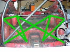
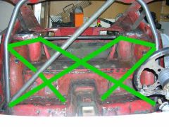
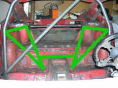
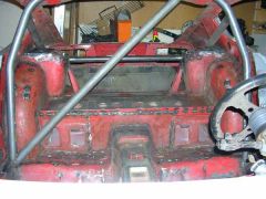
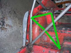
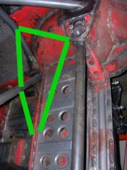
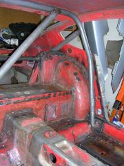
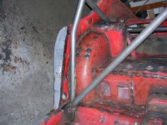
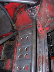
Thought this other picture would help too. My kinda crappy idea, tried to fix with a bar across the trans tunnel (this doesn't look like the answer to me): The X and a brace from the hoop to the floor: This just looks like too much to me, the X with the triangle design together:
-
-

-
I like my ACT pressure plate with a bone stock 225mm clutch disk. There are only two variables here, how agressive the pp is and how aggressive the disk is. I've seen damage to the thrust bearings and flywheels from puck style clutches, and while they're great for racing I just feel they're a bit overkill for anything else. Putting a more powerful pressure plate on with a stock disk also increases the holding power but is much easier to deal with on a day to day basis. Mine holds down ~240 whp no problem and is easy to drive. I don't believe that it is necessary to go too crazy with the NA engines, they just don't make enough power to require puck clutches in my experience.
-
Weber jets??All who live for their triples please read this
JMortensen replied to datfreak's topic in Nissan L6 Forum
EXACTLY! This is why triples and tall gears don't get along together. It's a high rpm induction system, and needs the rpms to work. 4.11's and 4.37's will help you stay in the rpm range where the carbs work. When I put triples on my car I actually went slower at autox than with SU's because I had a hard time keeping the rpms up high enough with my 3.70 gears. But get it on a big track where you can open it up and get the rpms up and OH MY GOD it is faster!!! -
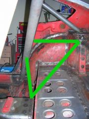
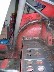
OK, so if you followed this thread: http://forums.hybridz.org/showthread.php?t=106457 you can probably guess where this is going. I want to tie the rear suspension pickups into my rollcage. The suspension pickup points are just to the sides of the tunnel in the back. I want to add a couple bars from the main hoop to the strut towers, and I also wanted to do an X from the strut tower to the bottom of the hoop on the opposite side like this: I'm thinking that this is a lot of weight back here, and maybe ultimately unnecessary. So in the interest of making the installation simpler, I've come up with another idea. I'm thinking that it needs some help though. It just doesn't look right to me, and I want to be sure I'm doing something worthwhile before I start notching tubes and welding things in permanently. So here's the pictures of the back of the car (blank slate in case anyone wants to sketch their better idea--hint, hint). So here's my idea. Make something of a triangle from the hoop to the strut tower, the tower down to the suspension pickup point (through the rear deck), and then back to the hoop. The main issue I think I'll have here is that the hoop is leaned back a lot for maximum head clearance, so the bar going from the hoop down to the suspension pickup wouldn't be the same left and right. On the right side it would have to intersect the diagonal in the main hoop, and from the inside of the diagonal it would have to then head in a more rearward direction to hit the spot on the floor. I don't know that this is particularly bad other than aesthetically. The other issue is that this idea doesn't tie the right and left sides together. So while the main hoop and the strut tower bar would connect the two sides, all of this other stuff wouldn't, which is I think a problem from a stiffness point of view. OK, here goes. Anyone have a way to make something salvageable out of this mess???
-

-
-
-
-
-
-
-
-
Final started chassis stiffening ...
JMortensen replied to heavy85's topic in Brakes, Wheels, Suspension and Chassis
I can SEE the scale on the plate that you welded, and your weld looks like you welded through scale. It's not a bumpy surface. It's a bluish colored coating, and it's on your plate steel that you're welding. You need to knock it back an inch or so from the edge. If you still don't believe me I can go out and grind some off of my big piece of plate and take a picture to show you. It's there though, and your welds will be A LOT better for getting rid of it. -
Final started chassis stiffening ...
JMortensen replied to heavy85's topic in Brakes, Wheels, Suspension and Chassis
You need to clean your plate before you weld it to the car. It has a coating called mill scale on it, and it will weld a lot better if you clean it off. I have some that has a SERIOUSLY tough coating on it, takes forever with a knotted wire wheel so I've changed to a flap sanding disk to get that crap off. Also if you're going to do the whole chassis I suggest you spend a couple days with a propane torch burning the thin layer of undercoating off of the body. I tried a heat gun and a scraper, it sucked. Then tried a wire wheel, it worked but was SLOW. Then got turned onto the torch. You just torch it until the coating starts to bubble, then you can scrape it right off and clean it up with a wire wheel. Overhead welding does suck and that's the main reason I made a rotisserie to put my car on. If you're going to stitch weld the whole thing or even if you're just planning on working underneath a lot, you might seriously consider going that route. I used 3 engine stands and some 1.5" square tube for most of it, a couple 1" square tube for gusseting. It was pretty easy to do and saves SO much hassle... Good luck with it! -
About 85whp/liter seems to be the limit for streetable compression ratios from what I've seen. Up the compression to 14:1, run a gigantic cam and rev to 9000 rpm and you might get up over 100, but then your engine's lifespan is measured in hours.
-
Never heard of a scatter shield for U-joints. The scatter shields that I've seen are all about the clutch and flywheel exploding, and preventing that from taking your feet and lower legs off. You can buy an appropriate bellhousing that works for the T56. They just make em out of 1/4" thick steel. For an L, there really isn't much out there. I kinda half-assed one together just by bolting 1/4" thick plate in the tunnel area near the footwell. You can also buy a Kevlar trans blanket. They're really supposed to be for trans gears coming apart, but it seems to me I've talked to a couple people who were using them for flywheel protection over the years. http://www.jegs.com/webapp/wcs/stores/servlet/category2_10001_10002_15519_-1 http://www.jegs.com/webapp/wcs/stores/servlet/category2_10001_10002_16731_-1