-
Member Statistics
33430
Total Members5167
Most Online
All Activity
- Today
-

Nissan L-Series Cylinder Head Flow Bench Testing and Development
DuffyMahoney replied to MONZTER's topic in Nissan L6 Forum
Gosh 240hp would be pretty bad for the amount of time put into my motor:) I guess time will tell -

Nissan L-Series Cylinder Head Flow Bench Testing and Development
MONZTER replied to MONZTER's topic in Nissan L6 Forum
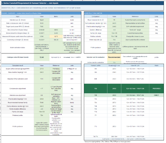
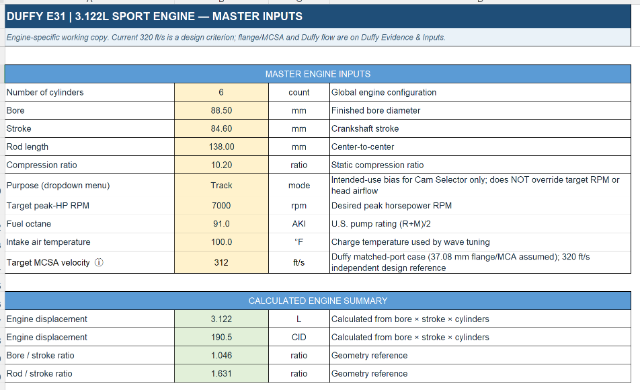
Hi Duffy, here's some more of the info I promised. Looking at your port size and flow numbers, I think your engine is pretty well suited to a 7,000 RPM power peak. Going with a much larger cam might shift the powerband higher without gaining much peak HP, especially given the head's airflow limitations. For a street-driven car, I'd favor average horsepower over chasing a higher RPM peak. I built my cam calculator around Kameari's range of cam profiles, with a dropdown for Street, Sport, Track, or Race to help determine the intended powerband. I originally had your engine set to Sport, which recommends the Kameari 70A at 241° @ 1 mm, or 232° @ .050" . Switching to Track changes the recommendation to the 73A at 253° @ 1 mm, or 244° @ .050". Your Bonk cam is 240° @ .050", putting it right between those two recommendations. So far, I'd say you made a pretty good cam choice. here is the cam recommendation tab in my calculator cam.pdf Next I'll show you the EAP simulated dyno curves for the different cams so you can see how they compare. I loaded all the engine parameters into my analysis program to compare the cams Here are the results. Of course some assumptions as usual, as I did not put the Bonk cam on my cam stand to actually measure its profile, so it is a educated guess where the Kameari cams are documented. As expected a little more top end a little less midrange but all in a good range for what you are building As a final note, in the calculator the simulation assumes ideal conditions, and these are engine numbers at the flywheel. so I would be very surprised to see these actual number, especially on a chassis dyno. What's important is the shape of the plot and getting the power where you want it and how you want it. This last one is my best guess of what your car should be around on a chassis dyno, 12% drivetrain loss and some reduction for real world conditions
- Yesterday
-

Fast Floridian's 240Z Track Build
jhm replied to FastFloridian's topic in S30 Series - 240z, 260z, 280z
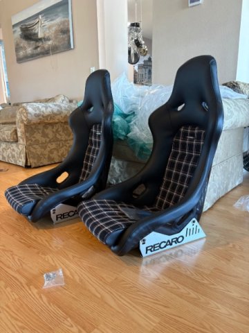
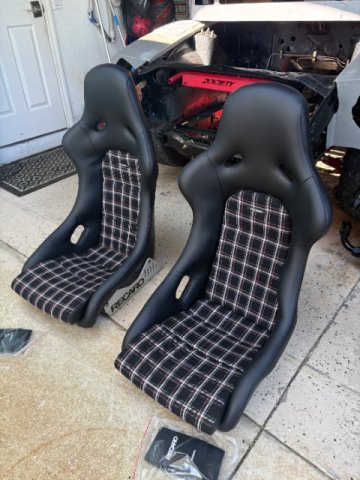
Very nice work (everywhere, on all components). I like the cool vintage-look inserts on the seats! 👍 -
11-08-2026. I finally got the broken exhaust manifold bolt out, got the new studs installed and then got the turbo header from Forever Fabrication mocked up on there, and re-clocked the Turbo and have it mocked up on there as well. PICS.
-

Fast Floridian's 240Z Track Build
FastFloridian replied to FastFloridian's topic in S30 Series - 240z, 260z, 280z
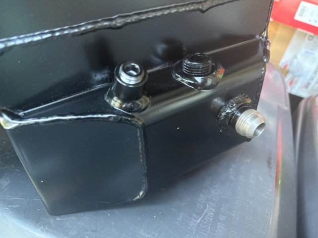
Welded the AN fitting on the oil pan, and my seats came came in 💪
- Last week
-

A 2026 SEMA SHOW 260Z Build all the way from Great Britain
toolman replied to toolman's topic in Body Kits & Paint
PART 20- WHAT HAPPENED TO THE SEMA SHOW 2026 260Z WITH GULL WING DOORS? wee, That is a good question. The Last Show they were still working on the Gull Wing Doors. Now the Here is the latest video from them but there was alot of unfinished customer cars in different stages of restoration but not completed. Let hope that 260z will somehow be completed and not just trashed. Please Comment about any unfinished project 2 cars that you might know of so other people can learn of the all of potential outcomes of their Dream Cars. -
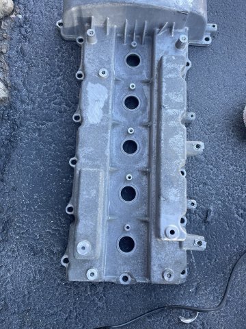
11-07-2026. Today was devoted to just the valve cover. I cut off all the tabs and brackets not needed, then trimmed off some of the "stubs" for wire ties, etc. and drilled out the 2 back breather ports for weld in female threaded -10 ORB fittings. I already have the screw in fittings, so that will be great. I also went ahead and drilled out the back portion for the oil fill bracket. To do this drilling, I had to carefully remove the baffles, which are VERY thin aluminum. I then chopped off the factory oil fill port ont he front chain cover and ground it down flush, and then took a piece of aluminum I had and made a plug to fit. Everything will now welded up, sanded smooth, and then the cover will go for a complete polishing at J&S Polishing in Colorado Springs. I had planned on cutting the chain cover potion down, but after taking measurements, the clearance is needed, ....I needed what was there so it will stay at this height.....it is different, as with the 6 cylinder cover, I had to take out approximately 3/4 inch. Progress pics follow. Cheers!
-
BIGBOSS240Z joined the community
-
Nissan L-Series Cylinder Head Flow Bench Testing and Development
MONZTER replied to MONZTER's topic in Nissan L6 Forum
For round ports like ours, these do alright, find the smallest location, and then measure this telescoping gauge with calipers , But remember diameter is different than area. With the diameter you can calculate area with an easy online calculator if you forget how to do it.
-

Nissan L-Series Cylinder Head Flow Bench Testing and Development
ihavearustedz replied to MONZTER's topic in Nissan L6 Forum
Super interesting read! Thank you. Today I learned about MCA (minimum cross-sectional area) in the port and how it relates to choosing a bottom end. Love it. What's the easiest way to measure the MCA in the port? -
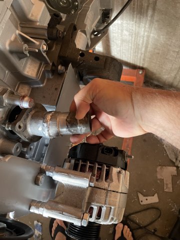
11-06-2026. Today I picked up the intake and fuel rail and thermostat housing. I then dropped off the intake to get powdercoated in "polished aluminum" finish. The fuel rail, work was simply turning and refitting the pipe to work better when hooking up the fuel line. Thermostat housing was for clearance. PICS
-
Nissan L-Series Cylinder Head Flow Bench Testing and Development
DuffyMahoney replied to MONZTER's topic in Nissan L6 Forum
Super cool stuff -
 I think both chassis are doable if you can get the engineering of the rear engine layout to work. If the rear engine layout doesn’t work out great then I suggest looking at a mid-engine layout in a 2+2. As a bonus the 2+2 is usually a lot cheaper as they are less desirable, at least here in Europe. I would suggest starting with a really good 3D model or scan of a S30 Z (model and year doesn’t matter to much) and try and work out the engine and transmission placement as much as possible while leaving the rear taillight panels in place. The rest doesn’t matter for now. This is an ambitious project but I’m really excited to see how you’ll handle it.
-
Nissan L-Series Cylinder Head Flow Bench Testing and Development
MONZTER replied to MONZTER's topic in Nissan L6 Forum
Duffy thanks, this lets me complete most of the analysis. Lets have a look at the basics first, I've adjusted details too better match your set up. I've also set it to track given your cam choice as it is better suited for higher RPM power and the resultant port sizing based on what you told me (Intake) Exhaust Intake Valve Exhaust valve Bowls so far all your specs align quite nicely with the workbook prediction for an optimal engine for trackish use with a 7000rpm peak power band. Ill get you runner length specs tomorrow and simulated dyno run numbers
-
11-05-2026. CHANGE OF PLANS. I am no longer going with the 4L60e automatic transmission. I got a 5 speed AR5 manual transmission for this build. 62K original mile unit inbound. Just couldn't get excited about the auto no matter how modified I was going to build it.
-
Nissan L-Series Cylinder Head Flow Bench Testing and Development
DuffyMahoney replied to MONZTER's topic in Nissan L6 Forum
I am getting roughly 294.5mm +-.25mm total length from head flange to velocity stack bell. Throttles with the stacks are =153mm Phenolic spacers =10mm Intake = (harder to measure since it isn't straight at all, center of bore to center of bore is 131.5mm Stacks have a max opening of 80mm, they taper down to 50mm at the throttle opening, then 48mm throttle blades, then 45mm at the intake to throttle flange. Then slowly taper to the port size of 37.08
-
 Thanks Mitchel, great tips, and the 250 GTO comparison made my day. Since the 2+2's extra length is in the doors, I'm thinking of using the shorter two-seater door and moving the rear wheel wells forward to take up that space. The car stays the same length. Does that sound doable from a chassis standpoint? I'll also take your advice on the radiators and fuel cell up front, water-to-air intercoolers, the front air dam and ducktail, and the cage. I'll check out Haltech too.
-
I could be wrong but I believe the extra length of the 2+2 sits mainly in the doors and middle of the car. That should make the rear wheel hub to rear body distance the same as a 2 door 280z. As the extra length of the 2+2 sits in front of the rear axle would it not be more beneficial to rotate the assembly and consider a mid-engine layout? I’m no 2+2 expert so I can only use my 2 seater ’77 280z as a reverence but this might give you more room to work with and eliminate the rear weight bias. Also consider adding some aerodynamic improvements to the car (especially the front) as the S30 Z’s naturally gain lift add speed. A front spoiler or air dam in combination with a ducktail spoiler should be enough for most Z’s. As for your other questions, if you brace the subframe good enough and also add a roll gage then I wouldn’t be that afraid of rear body twisting. Just extend the roll cage toward the rear and trinucleate the rear quarters. As for cooling I would keep the radiators in the front together with a good size fuel cell and use water to air intercoolers for the turbo’s as you still want to increase front weight. As for ECU’s it’s mainly up to (the tuners) preference, I personally like halltech as they have a lot of support and pre made aftermarket engine harnesses. But the most important thing is just doing what you really want to do and making your dream a reality. I really like the idea of this project and love the renderings, the front arches reminds me a bit of a 250 GTO.
-
Nissan L-Series Cylinder Head Flow Bench Testing and Development
MONZTER replied to MONZTER's topic in Nissan L6 Forum
Hi Duffy, I calculate it from seat to bell mouth end but I already know port length, so Intake runner length from Head flange to Throttle body. (I was guessing 110mm), TB Length of 88mm long, another guess, and 65mm velocity stacks a third guess, so it will be good to know exactly, thanks -
Nissan L-Series Cylinder Head Flow Bench Testing and Development
DuffyMahoney replied to MONZTER's topic in Nissan L6 Forum
How would you like intake runner length? Total from the stacks to the head? Cam is .525" lift and duration of 240 @ .05 valve lift -
Thanks for the honest feedback, everyone. rturbo, flatout, I hear you on the weight bias. flatout, your packaging math is exactly what I needed. I'm planning to move the rear axle line forward with a shorter 2-seater door so the transaxle outputs line up and the halfshaft angles stay under 15°. That should pull more of the VR30 inside the wheelbase. I know it'll still be tail-heavy, so I'm planning a reinforced rear subframe, a cage, and coilovers tuned for it. On budget and experience, I'm going in eyes open and doing as much of the work myself as I can. Still hoping a 2+2 owner can share the hub-to-bumper measurement so I can firm up the numbers.
-
 That’s a fair point — I wouldn’t use this 1.5 mm Z-pipe as a primary header or turbo manifold either. The intended use is downstream custom exhaust routing, where the main problem is packaging around existing components rather than supporting the turbine or collector. In that position, 1.5 mm stainless is a very different application from a manifold seeing direct turbine heat, concentrated collector stress and repeated flange loading. The part is mainly useful where two pipe paths need to cross in a compact space. The printed junction gives a controlled internal divider and repeatable geometry, but it does not remove the need for proper support, purge welding and a good transition to the connecting tubes. I agree with you on the manifold side: 321 and a thicker wall make much more sense for long-term durability, especially around the collector and wastegate. For the Z-pipe, I would still treat the actual vehicle, heat exposure, unsupported span and hanger layout as the deciding factors rather than claiming that 1.5 mm works everywhere. Also agree on back-purging the manifold. Solar flux can be useful when purging is difficult, but I would not treat it as equivalent on a highly stressed turbo manifold. Fixture the flange during welding, control the heat input and check it flat afterwards — that is usually more important than the material debate alone. Your point about ceramic coating and heat shielding is also well taken. On a street or competition car, shielding the master cylinder, wiring and nearby components is often more valuable than relying on the coating to survive indefinitely at the collector.
-
Nissan L-Series Cylinder Head Flow Bench Testing and Development
MONZTER replied to MONZTER's topic in Nissan L6 Forum
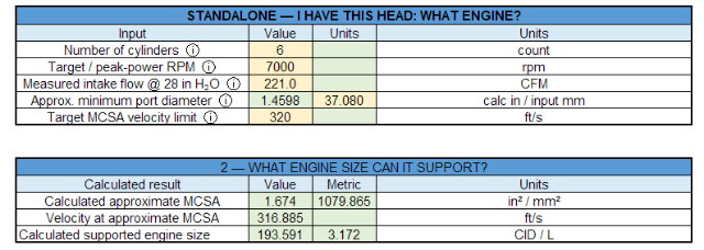
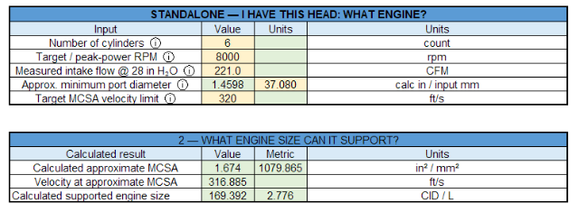
Duffy, that helps quite a bit. With the 37.08mm measurement being the equivalent diameter of your port opening, and that the flange is at or near the MCA, this changes my original calculations considerably. At 221 CFM, the calculated velocity through that opening drops from 356 ft/s with my original 35mm assumption to about 317 ft/s. That's almost exactly the 320 ft/s design target I was using for the L-series port. Using that new dimension, 221 CFM and a 7000 RPM peak horsepower target, my calculator comes up with a 3.172-liter engine. That's remarkably close to your actual 3.122L. So based on these assumptions, your displacement and intake port size appear to be pretty well matched for a 7000 RPM power peak. That's encouraging, especially considering your goal is a responsive street car rather than an 8000 RPM race engine. (At least what I think, for what its worth) I also did a rough port-volume calculation using your 45mm intake valve, an assumed 90% throat (40.5mm), an 8mm valve stem and the port centerline length from my E88 measurements. Assuming a gradual expansion from the flange toward the throat, I get approximately 124cc. That's only a geometric estimate, since we don't know the actual CSA progression or how Andy shaped the bowl and short side. We will use this number later to look at average port dimeter. What Andy is doing around that short-side turn is particularly interesting. If he's increasing the area and controlling the flow as it approaches the valve, that could help explain how he's getting those flow numbers without an excessively large flange opening / MCA. The one thing we still don't know is whether 37.08mm is actually the smallest section or whether the port necks down somewhere else. On L-series it is typically pretty close to the flange or about an inch in before the turn. But this new information makes your 221 CFM result much easier to reconcile with the port geometry and displacement, and it suggests your existing combination is reasonably close to the type of driving you described. The next step would be looking at your actual cam timing and intake runner length to see how well they're matched to that 7000 RPM target. We can do that in the rest of the tabs in my calculator Im working on But look when we put that head on a 2.8, A real ripper at 8k
- Earlier
-
Nissan L-Series Cylinder Head Flow Bench Testing and Development
DuffyMahoney replied to MONZTER's topic in Nissan L6 Forum
Looks like I am 37.08 This is the porting plate used to port match my intake to my head. Each aspect is port matched. Picture is prior to port matching, but shows the bends My porter (Andy) secret sauce is how he does his short bend, but I have no idea exactly how he does it. He seems to think the E31 can flow the best and is the best for "race engines" My car is a street car, so overall my goal is fun drive around and doing canyon driving.
-
Hey all, I'm mainly looking for 280Z 2+2 owners. Could someone measure from the rear hub center straight back to the rear body panel, and to the back of the bumper? I'm checking whether a rear-engine VR30 swap will fit, and I can't find this number anywhere. Please include your car's year and whether it's a US car. Thanks! Chibuike
-
 what is the final use of the combo? I wouldn't use 1.5mm a header/manifold for anything other than a dedicated drag car. I'm not a full time fabricator, but I've made a hand full of turbo manifolds with pretty good success for street cars over the years and my experience is I choose sch 10 pipe. (.109 or 2.75mm wall),But I choose 321 not 304. I have used SCH40 304 (~.140" or 3.5mm wall) but I don't think that is necessary unless your looking for extreme structure and weight is no concern. 321 seems to hold up better over time than 304. I've also probably gotten better at welding over the years but I have had two 304 manifolds end up cracking at the wastegate/collector after about 10 years and two 321 manifolds still holding strong. But i also have a handful of 304 that didn't crack. (at least not yet) I recently just made one for my Z out of 321 based off that information as well. As far as back purging. Id say for a manifold its 100% necessary. Its always a pain in the butt and I'm not sure what the best technique is. I do use solar flux regularly on larger diameter pipe like downpipes, turbo backs, or turbo cross overs for V8's with good success too. I feel those structures don't see quite the extreme stresses that a manifold does so i don't know if its as good as back purging. I would say if you can't backpurge then solar flux is the next best thing. as far as flange warping. you need to bolt it down to some sort of flat fixture for all welding. i've had a few that still bow a little and need to be sanded/milled flat but usually if you have it bolted down it holds up fairly well. After the turbo I use .065 (1.65mm) 304ss for the first elbow of the downpipe and have never had an issue. street, drag, drifting or road racing. back when i drifted i would cook ceramic coating off at the collector. I do think some people have good success with it tho so maybe an installation concern. but other wise i header wrap everything. and use a quality turbo heat blanket and heat sleeving around anything important. A master cylinder requires a shield for more organizations.
















-
Who's Online 1 Member, 0 Anonymous, 828 Guests (See full list)