

toolman
-
Posts
518 -
Joined
-
Last visited
-
Days Won
7
Content Type
Profiles
Forums
Blogs
Events
Gallery
Downloads
Store
Posts posted by toolman
-
-
Richard,
Looks like a nice installation! Roughly how much did it cost you? I am considering it for my car. What rear gear ratio
are you going to run? I would guess about 3.90 with a T-56 trans. Is there a lot of these swaps out there?
Toolman
-
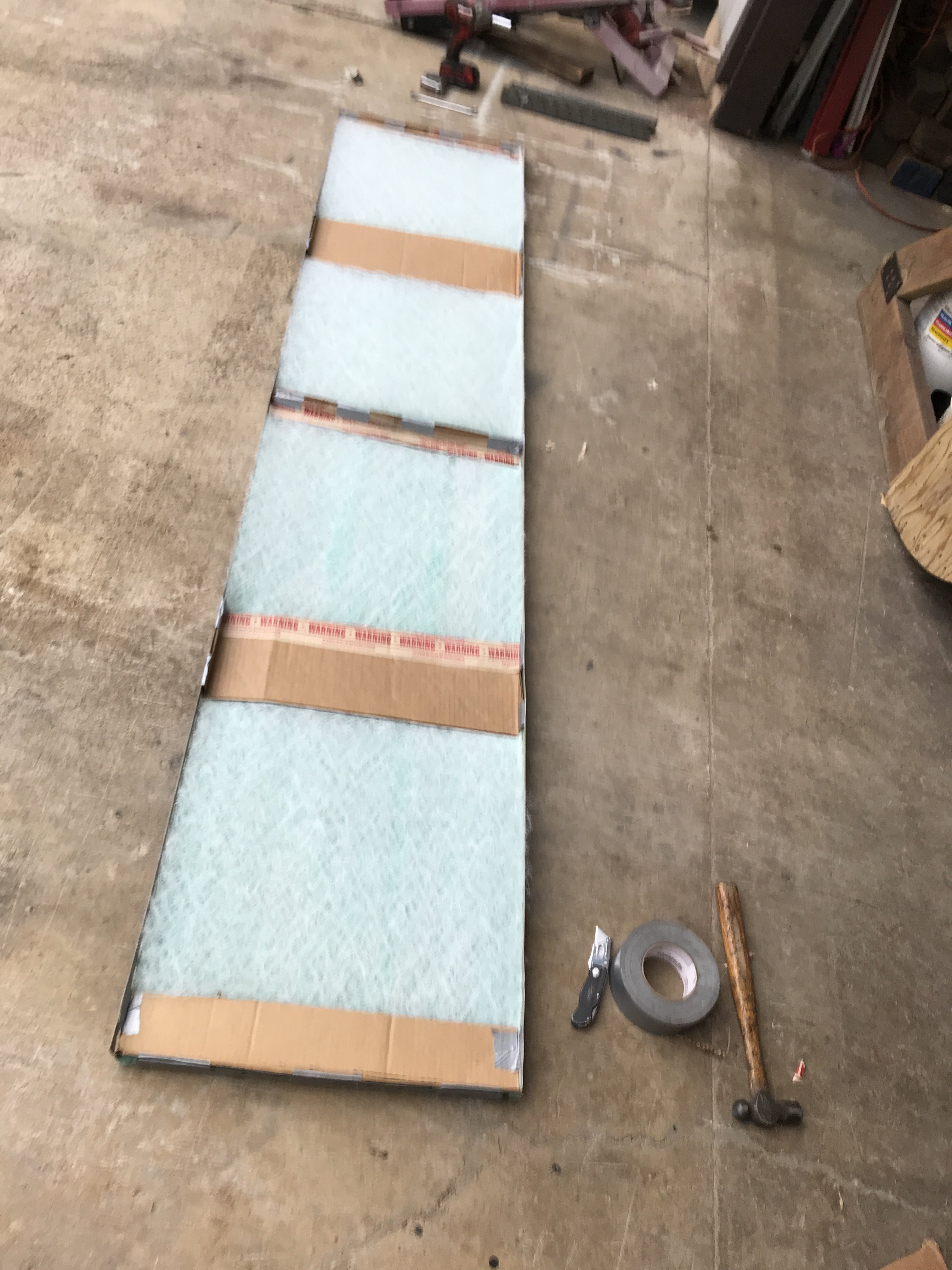
Picked up four intake filters 20" x 20" and four exhaust filters 20" x 20". Fabricated a metal frame out of some right angle 1/8" vertical shelve poles.

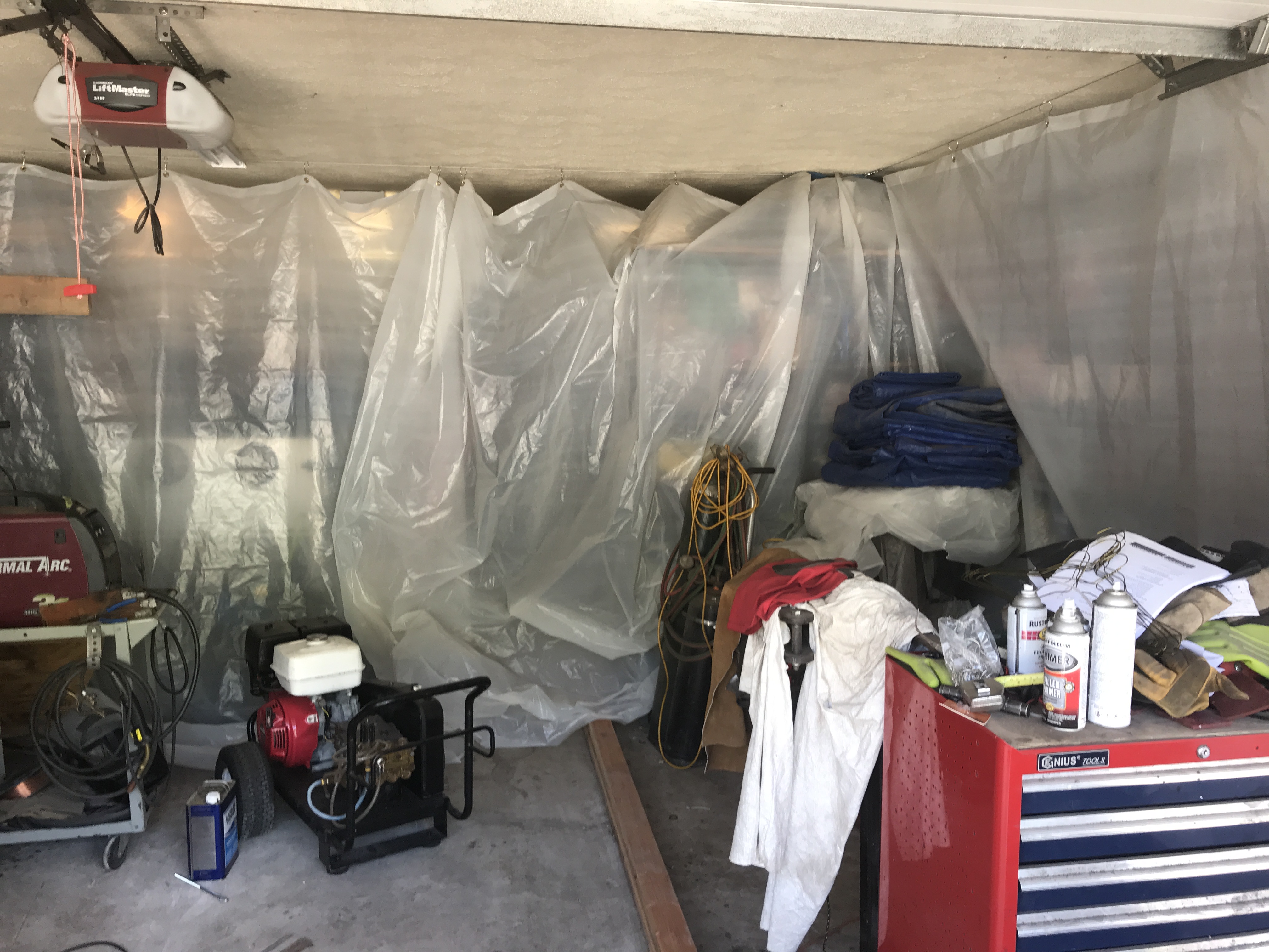
I hung a 10" strip of sheeting about 3" in front of the curtain cable by stapling to the ceiling. The gap was necessary to allow curtain movement but be close enough to seal the curtain to the ceiling. With the fan running, you can see the fan pressure is sufficient to seal the curtains.
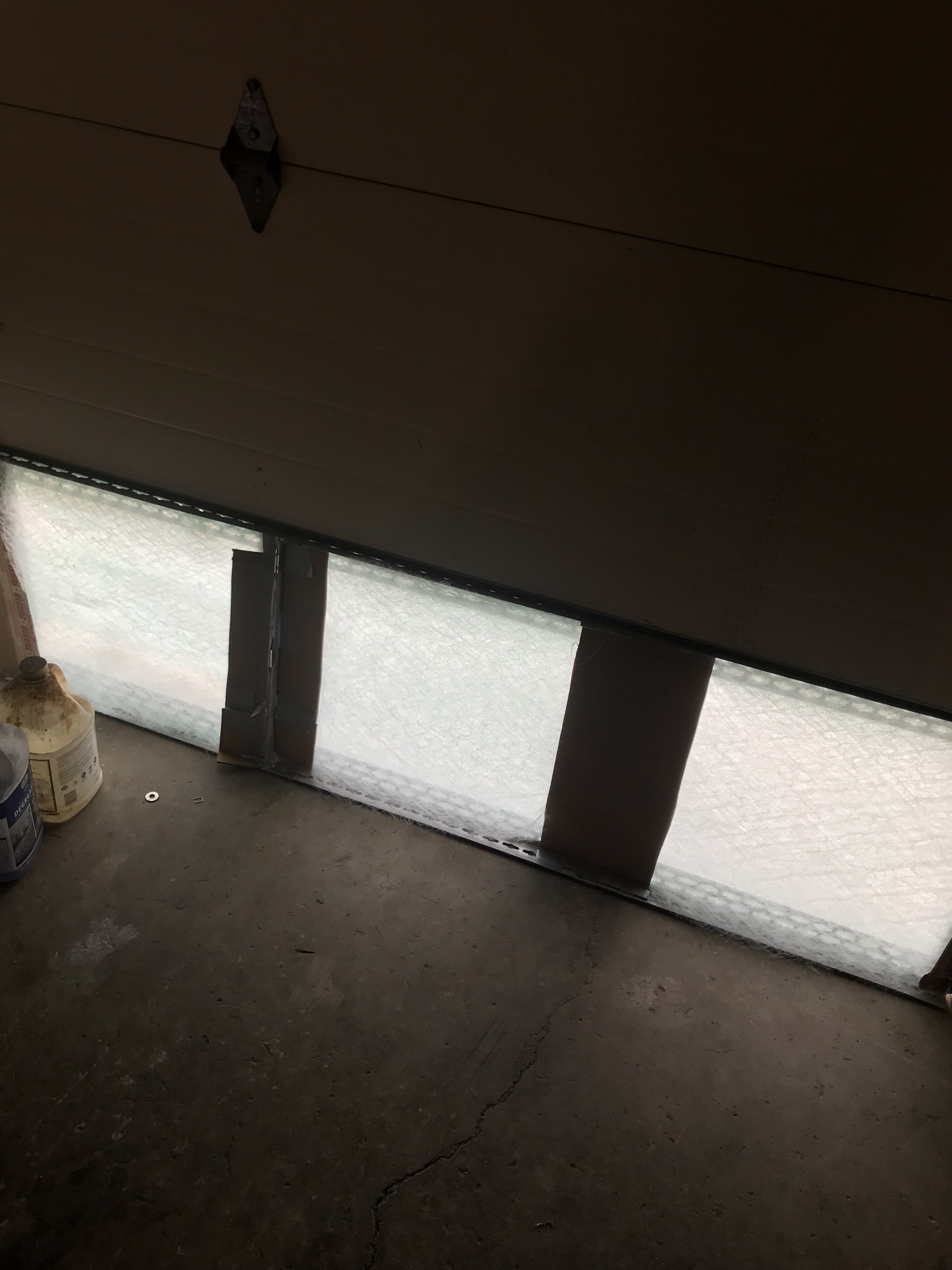
Outside view -The garage door was lowered to the #1 exhaust filter frame and #2 block off frame.
Inside view of exhaust filters
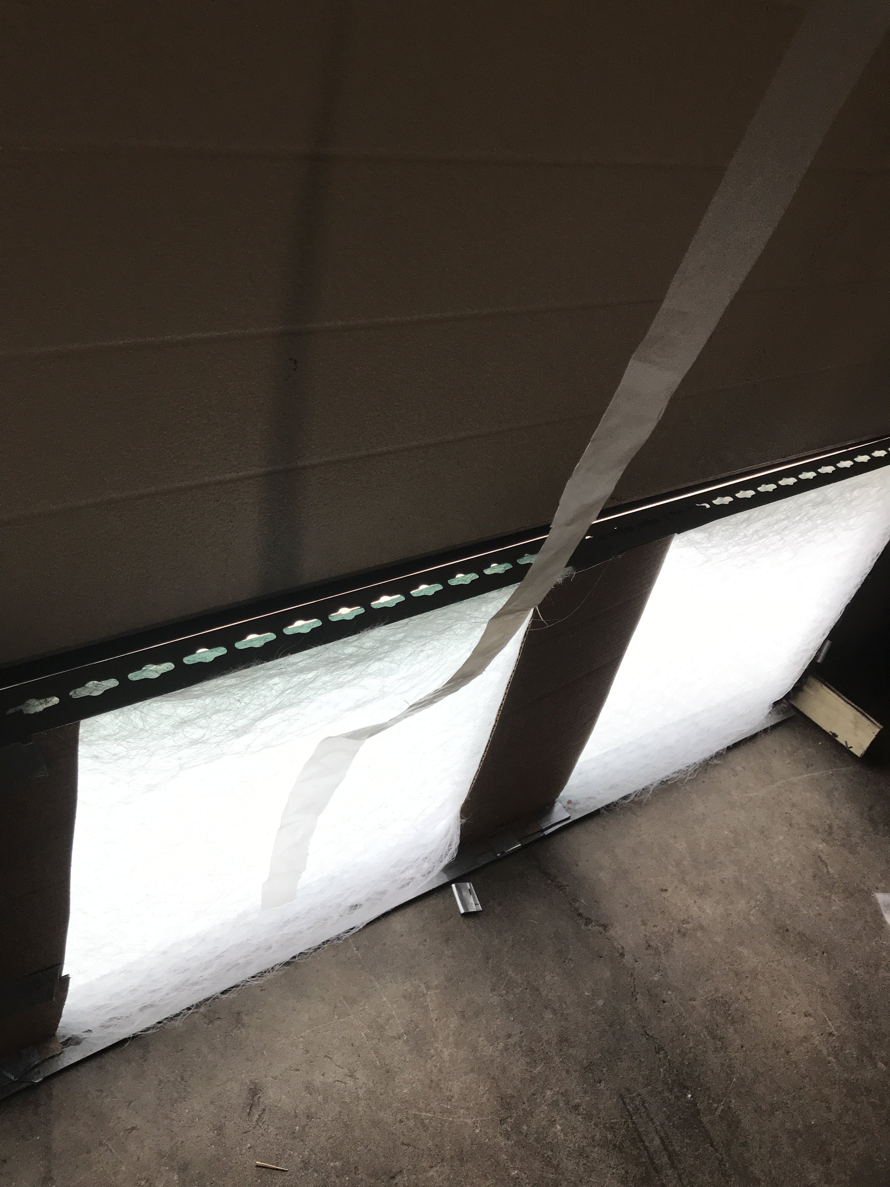
The booth airflow test consisted of hanging thin strips of plastic sheeting in the air to observe its movement. As you can see, the test strip near inside exhaust filter is being drawn against the filter-indicates sufficient airflow leaving the booth.
.
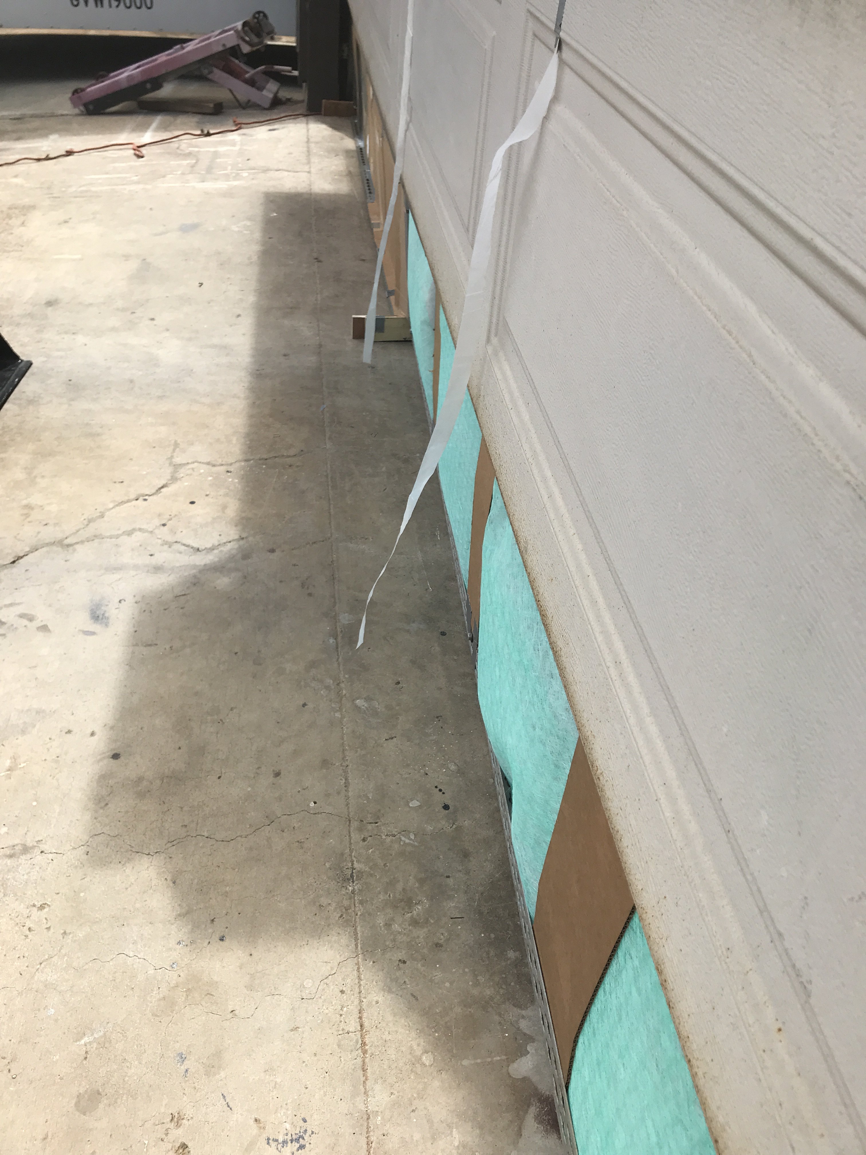
The outside test strip indicates outward airflow also.
After more testing, I found one of the exhaust filters had pushed out of the frame. So I added some metal screen on the inside to stiffen the exhaust filters. That seem to solve that problem. I spent a little more than $200 of materials to build to this booth( mostly from Home Depot). This booth suits my needs and requirements. I hope you guys found its construction interesting.
Added screen wire to stiffen the filters.
-
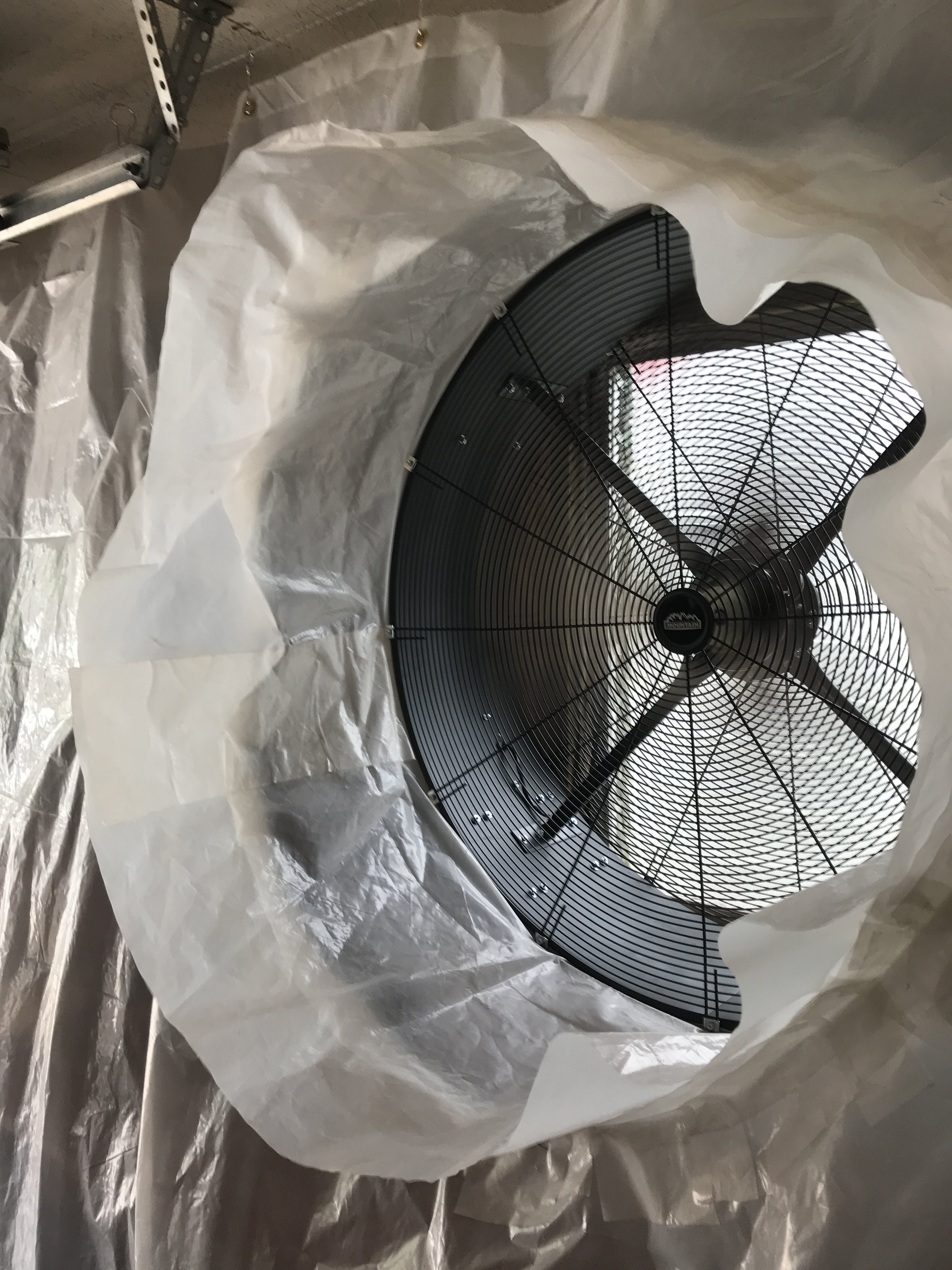
The photo shows the fan duct folded up and held in place with 3" wide strap. The strap is duct taped to fan body and the other end is velco attached to opposite side of fan.
Extra grommets were added the area above the fan for more support.
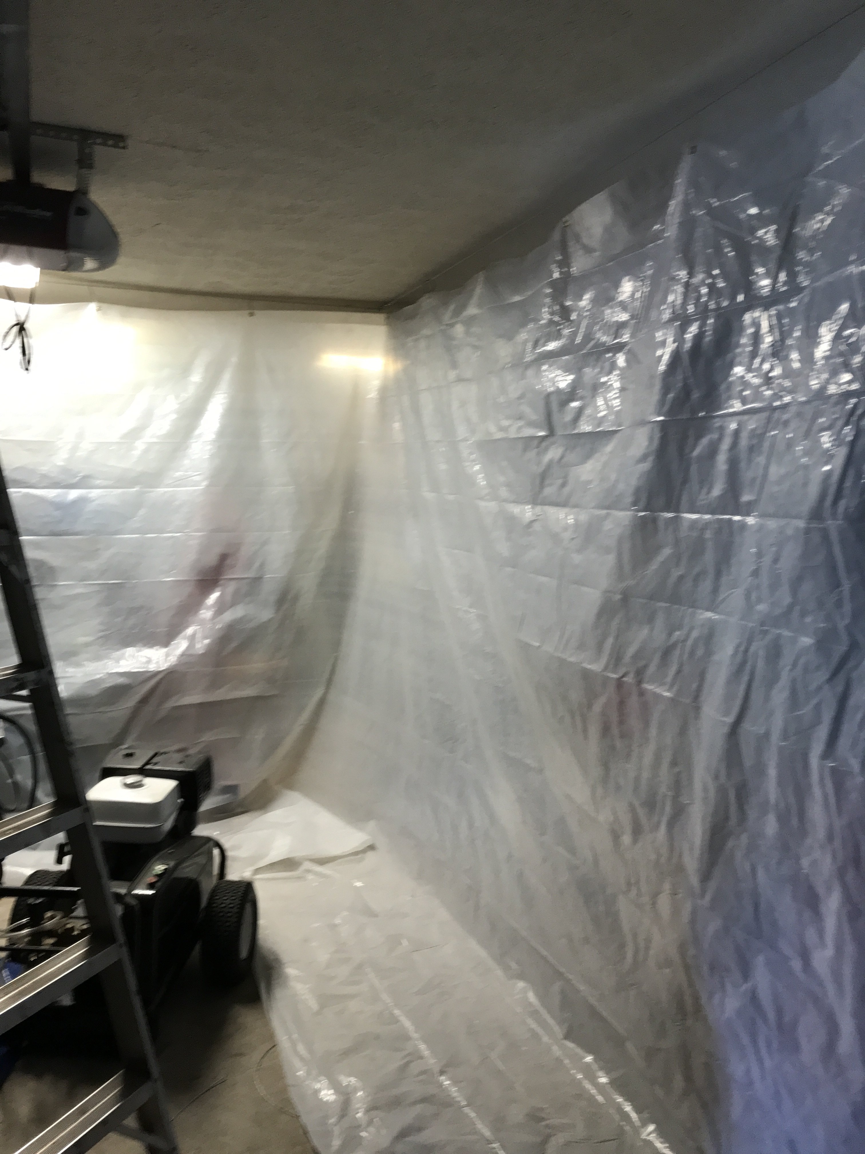
When the curtain is open and aligned with the fan, it looks like this.
Once the fan is switched "on" , the incoming air pressure basically seals itself in the curtain wall.
It works like those inflatable bounce houses for kids. When finished using everything folds up nice and neat.
-
Decided to enlarge the booth size from 1 1/2 car to 2 car size for various reasons: more room to paint, left side curtain closer to fan and easier
to use. Also, now the garage door does not have to be closed to utilize the curtains. The following photos show the improved booth design.
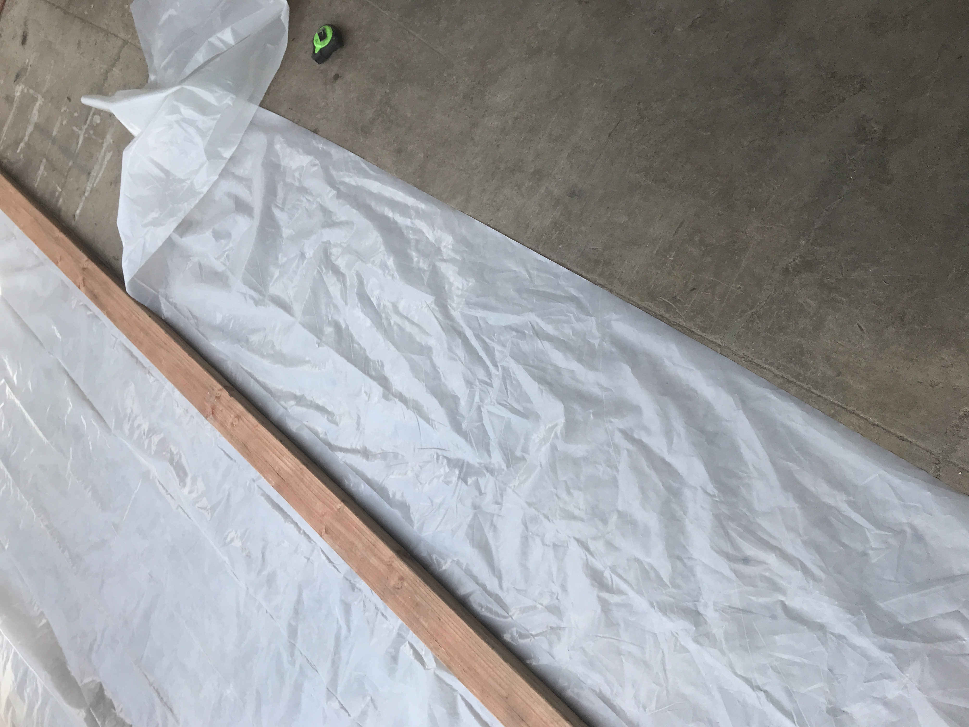
After trial fit, 24" was removed from the bottom of the curtains. 4" was allowed on the bottom to be held by a 2 X 4.
Made a duct out of scrap sheeting to connect fan to curtain. No sure how to attach duct to curtain. Might try putting the duct hose into another hose section attached to the curtain.
Left curtain must also be modified for fan to blow through but still allow to be folded up.
-
Sorry about the inconvenience, I deleted the Garage Booth-continued post and am reposting it here.
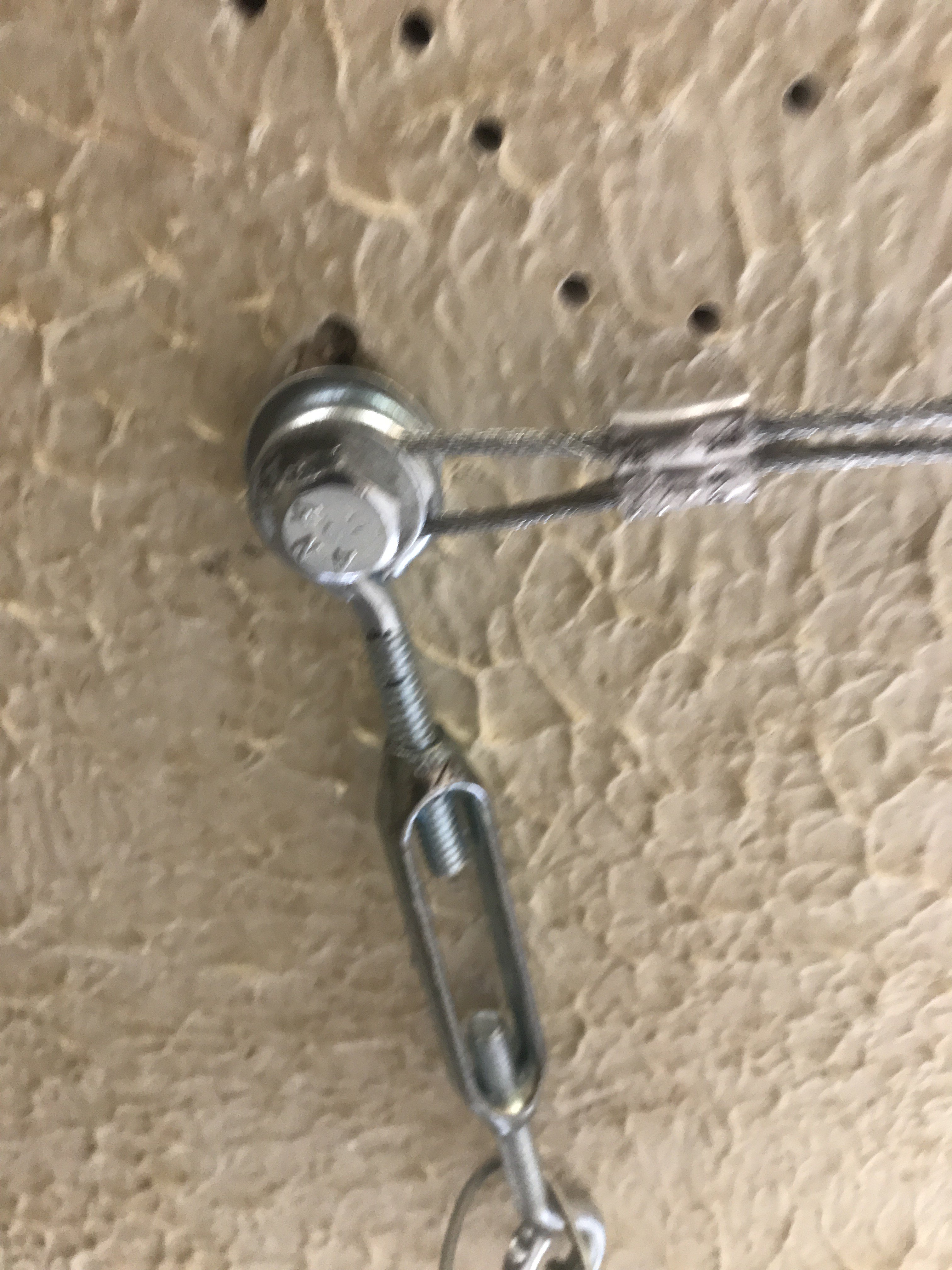
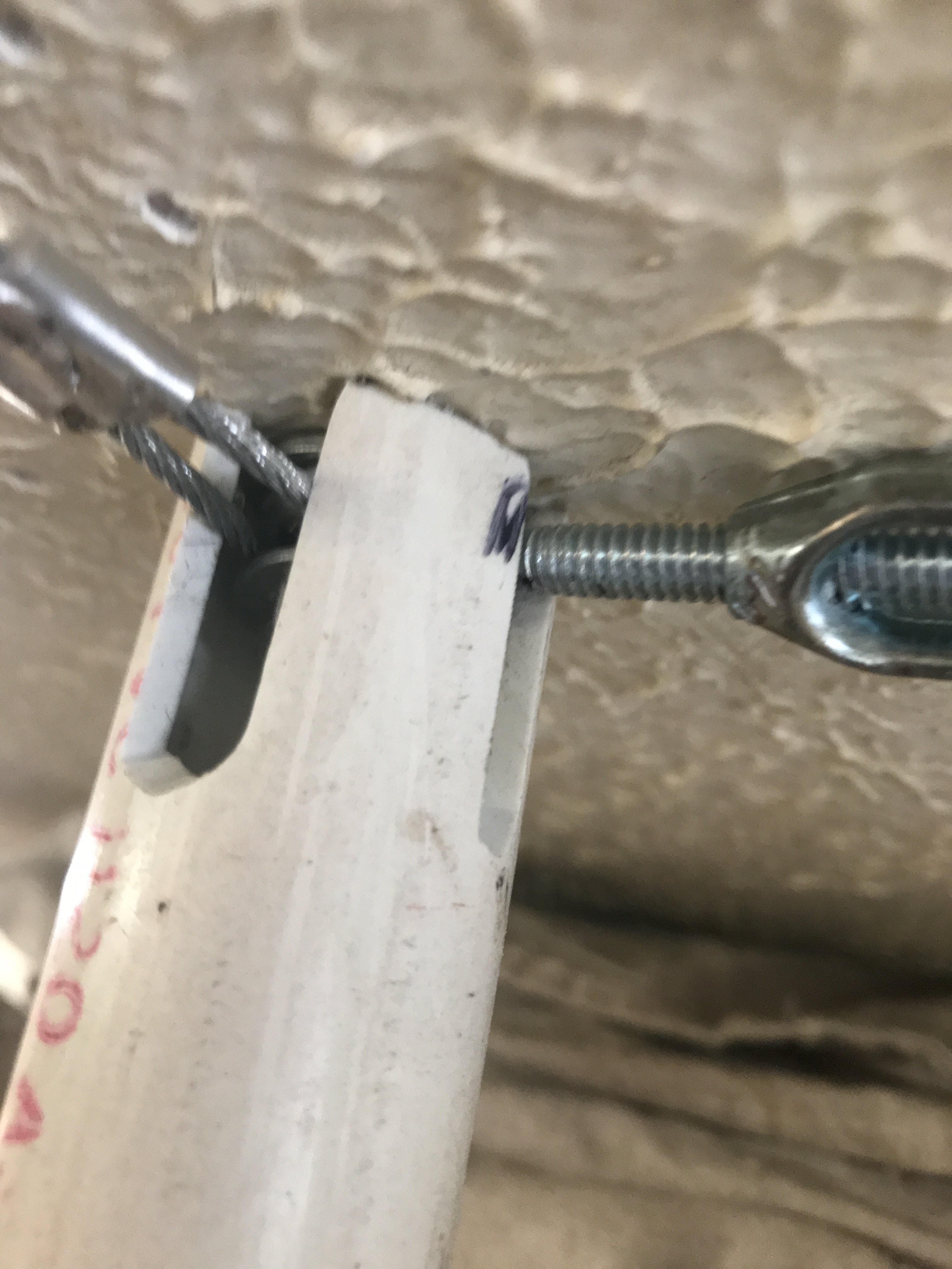
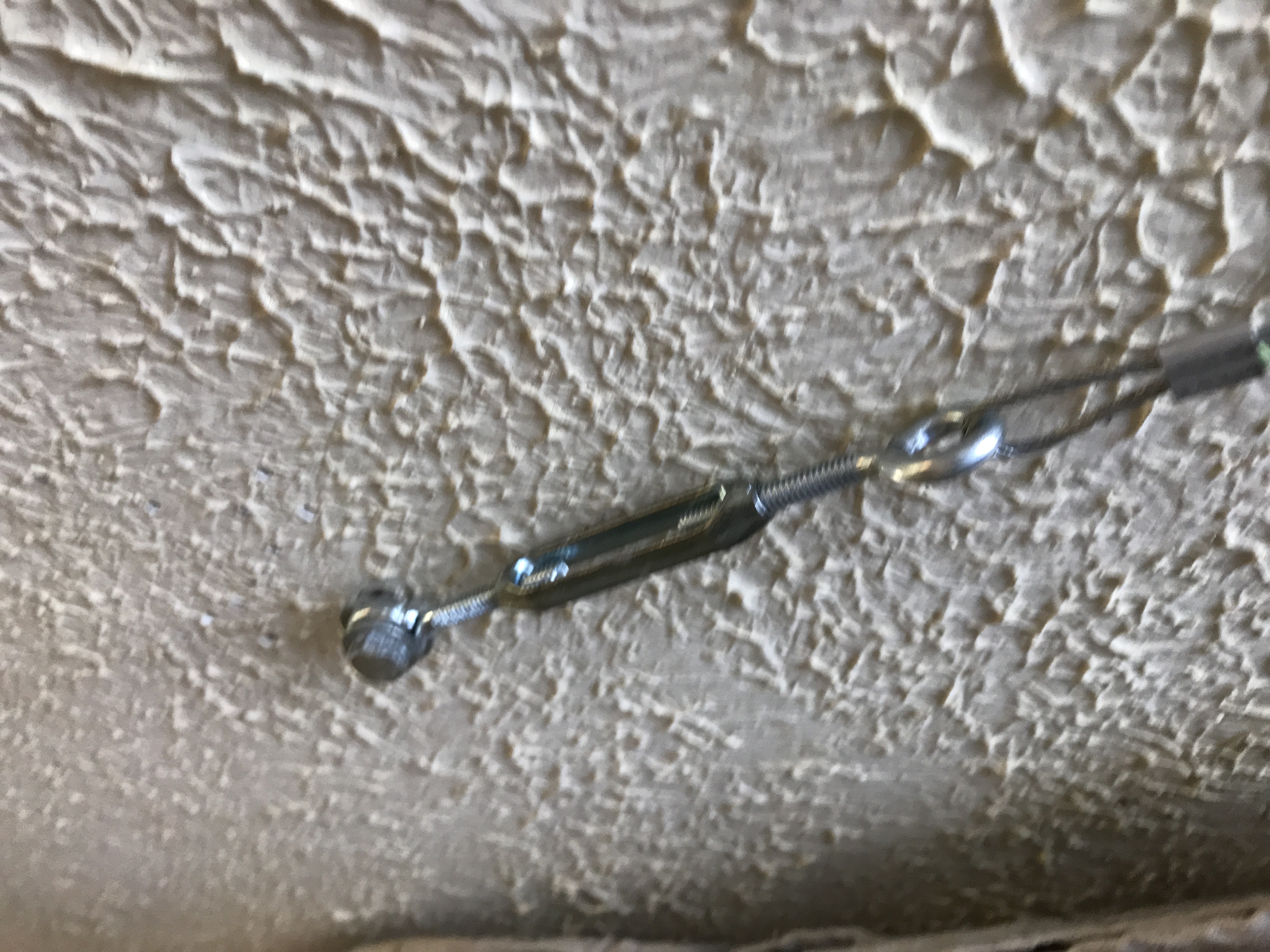
Closeup of the right corner of garage booth
It uses a 2 1/2" lag screw to fasten two 3/ 32" curtain cables in garage roof rafters. The turnbuckle provides cable tension adjustment.
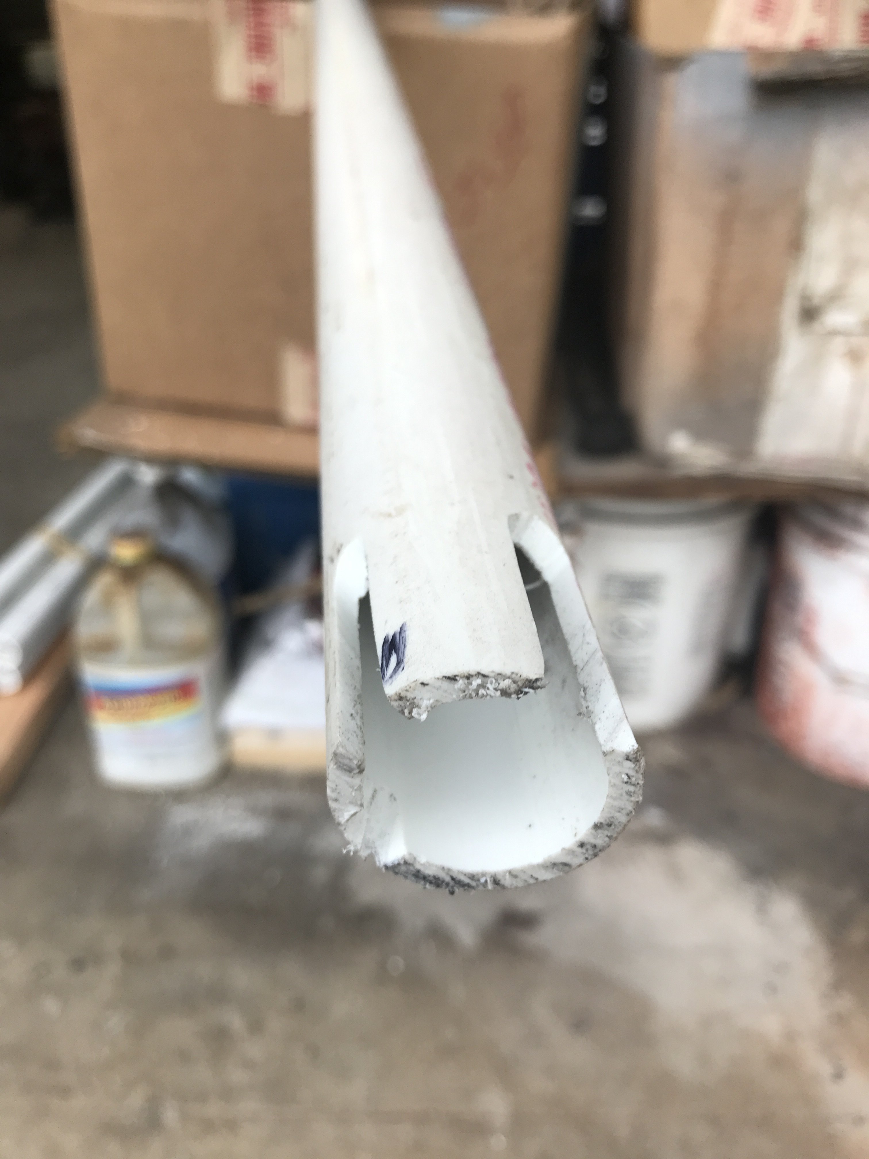
A 1" PVC pipe is used to be booth corner vertical support. It is slotted with a cutoff tool to fit tightly into the corner cable arrangement.
The slotted PVC provides a stable vertical brace.
Next a bottom mount of this PVC pipe must constructed.
-
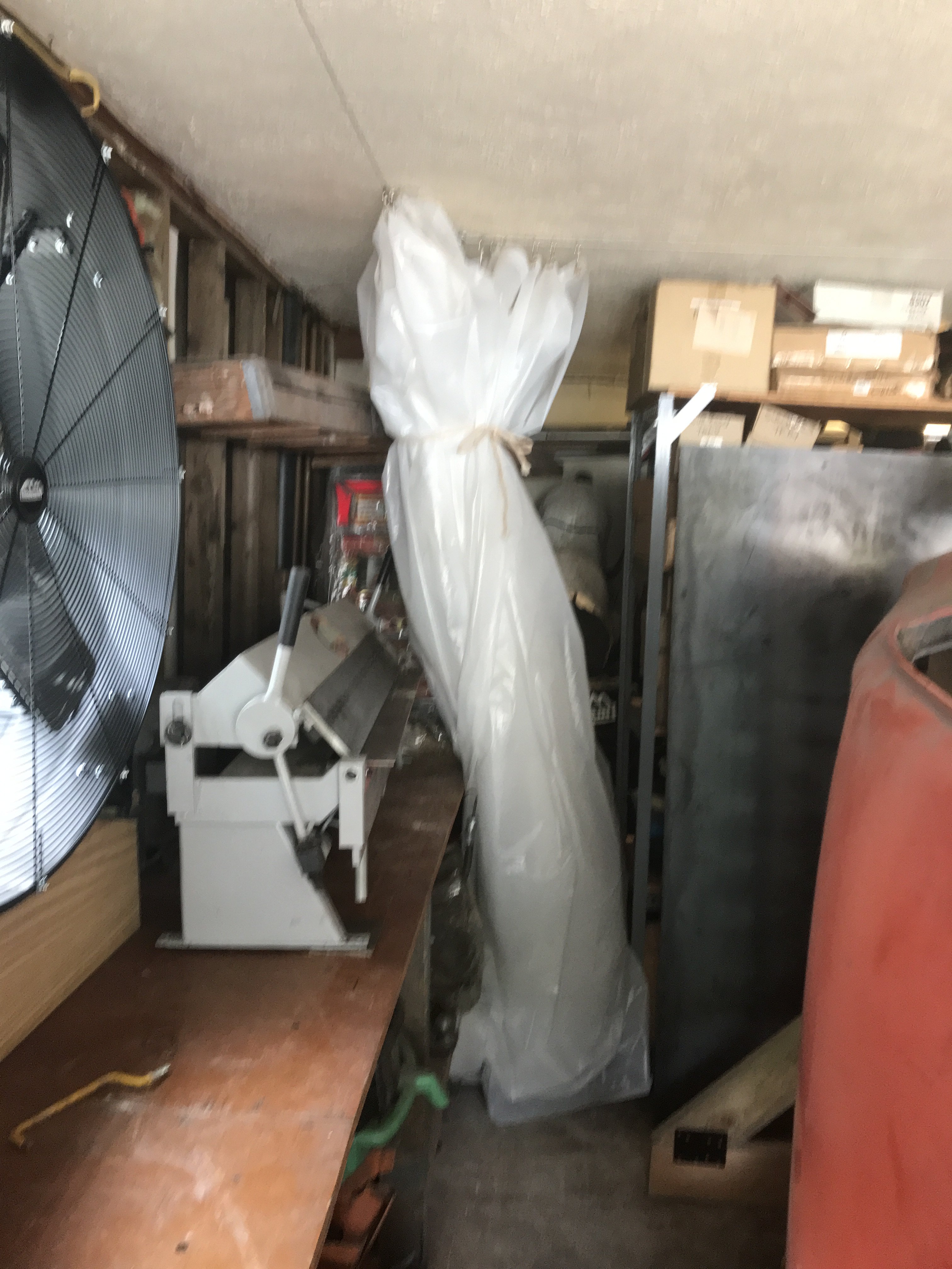
Right curtain closed up. When the bottom of curtain is trimmed. the curtain close up into a much smaller bundle.
-
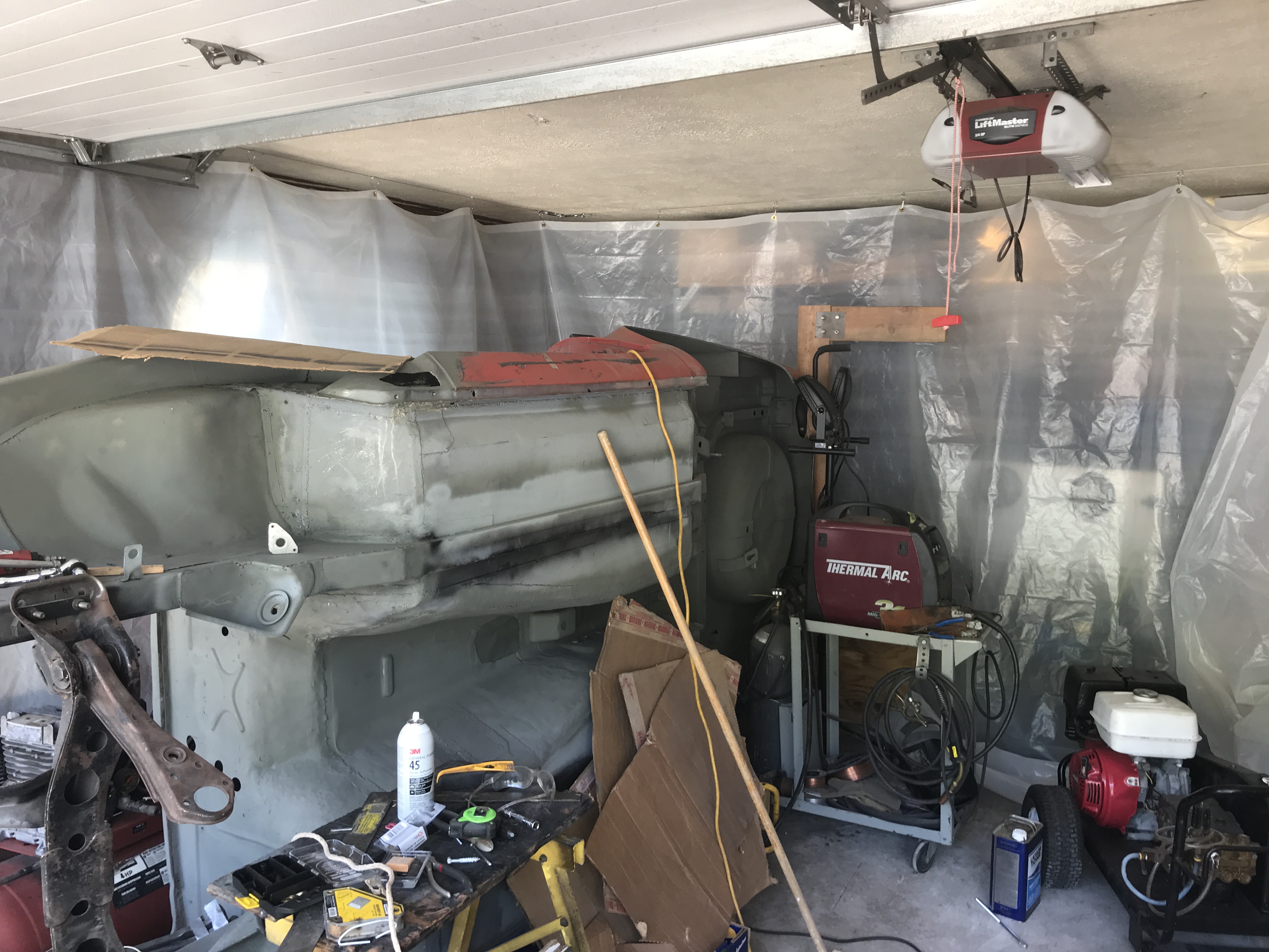
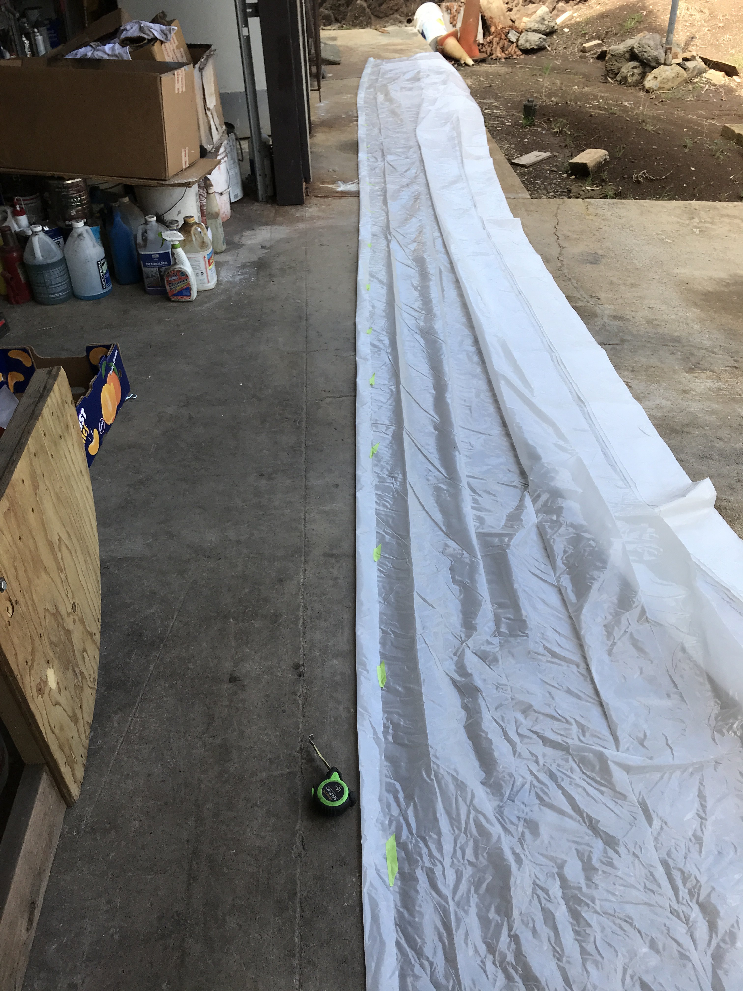
I wanted my spray booth to be easy to utilize and store away. After searching the Internet for ideas, I decided to just build the booth that would be the best fit my situation. The booth would
consists of basically four 5/16' x 4" lag screws inserted into the garage rafters. One reason being that this method will completely clear the garage door when it is closed. Also another
advantage of this design is its versatility. The booth dimensions can be changer just by moving these four bolts and 3/32" cables. I used plastic sheeting 25' long x 9' high and 6 mil
thick. I think the thicker sheeting is superior unless the booth was going to be used only once.
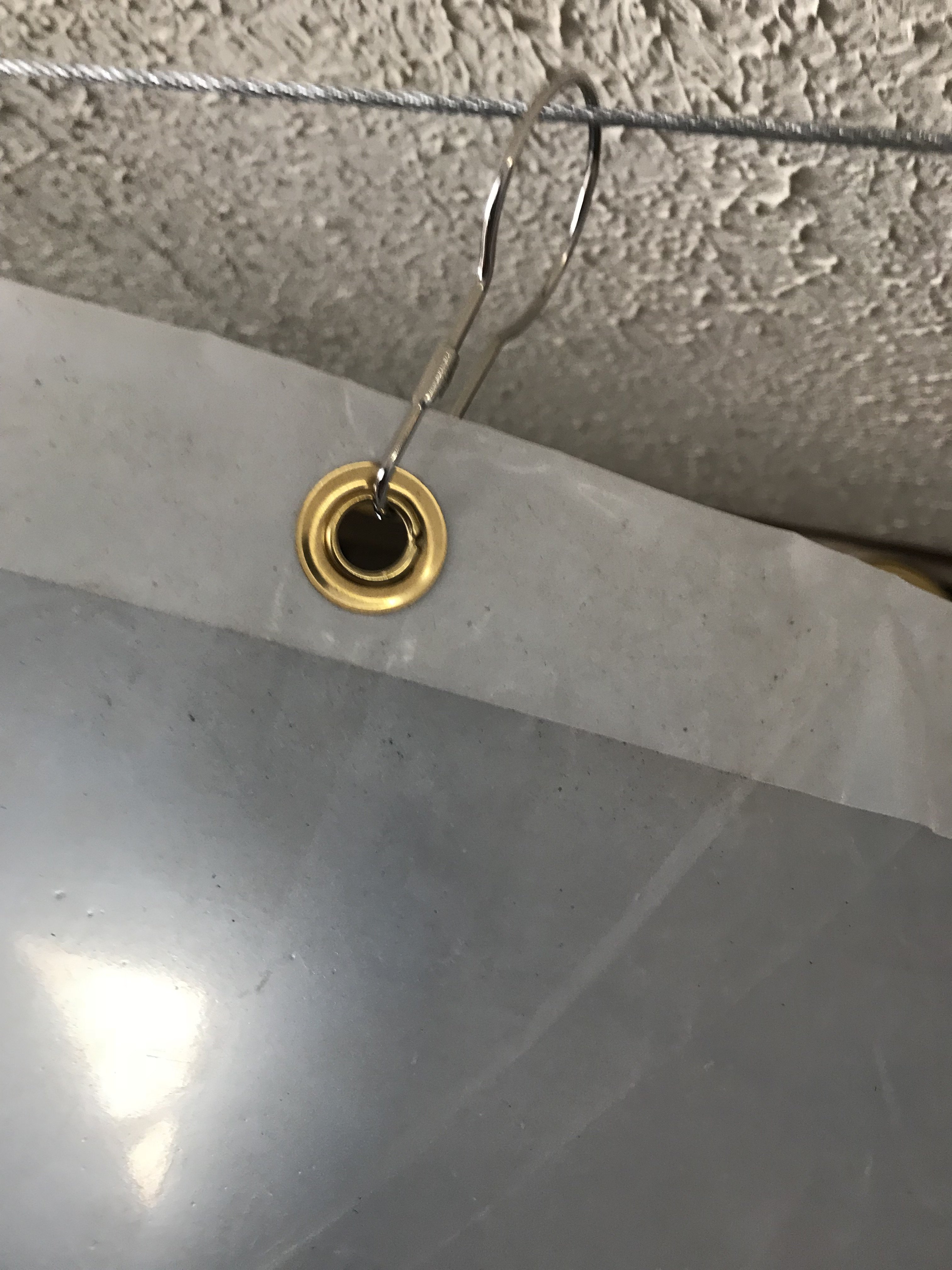
The top edge of the sheeting was folded over 2" and glued to add strength. General Tool 3/8" brass grommets were installed into this edge area. They were spread apart 24". More grommets can added if necessary for support.
A 5/16" x 4" lag screw is installed in the garage rafter. All four 3/32" cables has one 5/16" turnbuckle to adjust tension to prevent sagging.
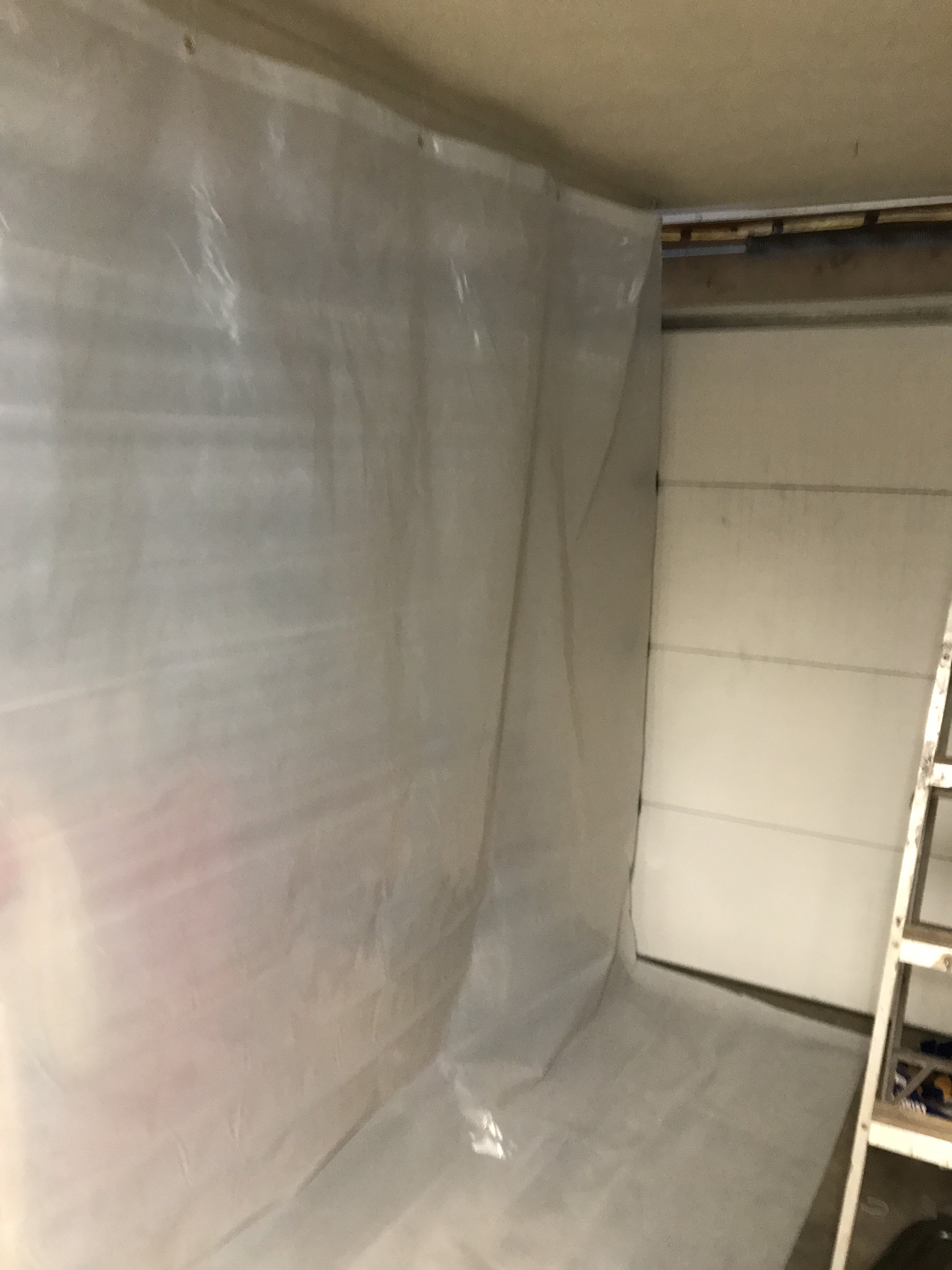
The rear and right side booth walls assembled. Note that final trimming of the bottom edge of the sheeting has not been done yet. Still waiting for sheeting top hooks to determine final height.
-
Sorry for not posting in awhile. Had rewire my Honda ATV, paint patio railings and my wife hit a parked car. Then we went to Hokaido Snow festival in Japan.
Nismo Festival had all sorts of Nissan car-street to race carsDrifting is very popular in Japan. Probably because it does not require a large race track. Also, the locals can participate in drifting as it is not as costly as road racing and use basically flat and empty parking lot.
Now back to the Z project. I decided to make a temporary paint spray booth in my garage. It will be only for epoxy priming for my Z. Not sure how radical that I will go with this booth.
Might use 1 1/4" PCV pipe to build the booth frame. It will have intake and exhaust filters and lights probably LED ones. As you can see,it will be a positive pressure booth. The main
reason for the booth is to prevent epoxy primer from going on everything in my garage. That stuff is impossible to clean off. My Man Cave is getting more elaborate quickly.
inside view of booth fan Outside view of fan with louvers open
-
Doing some of the small welding stuff before wet media blasting.
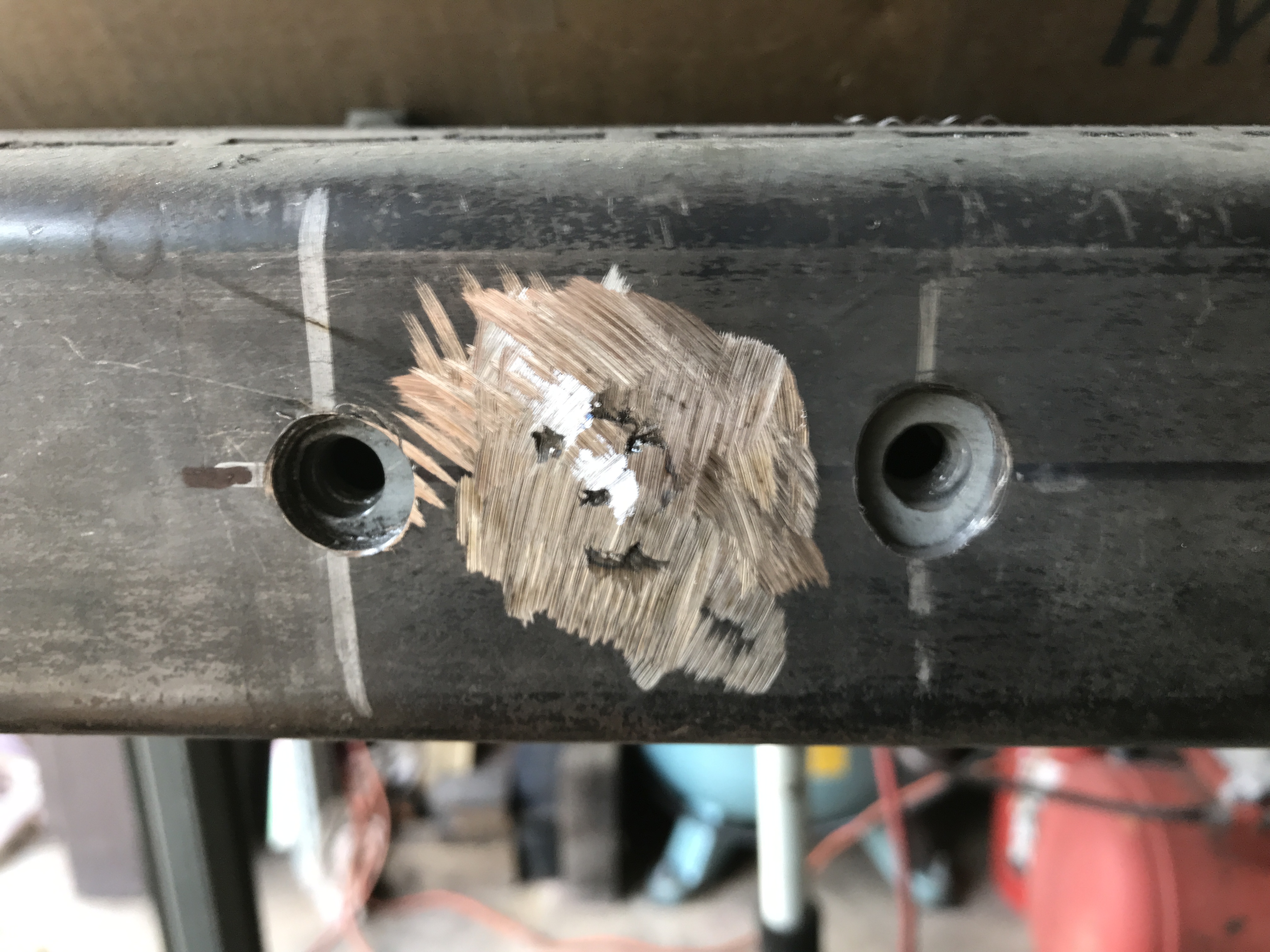
Stabilizer mounting holes
Two 8mmx 1.25 nuts welded to 1/8 x 6" steel plate
This mounting was taped to 3/16 tubing to install in frame tubing.
for hole alignment. With alignment done, the mounting plate is plug welded to frame rail. I hope this additional details were helpful to someone.
-
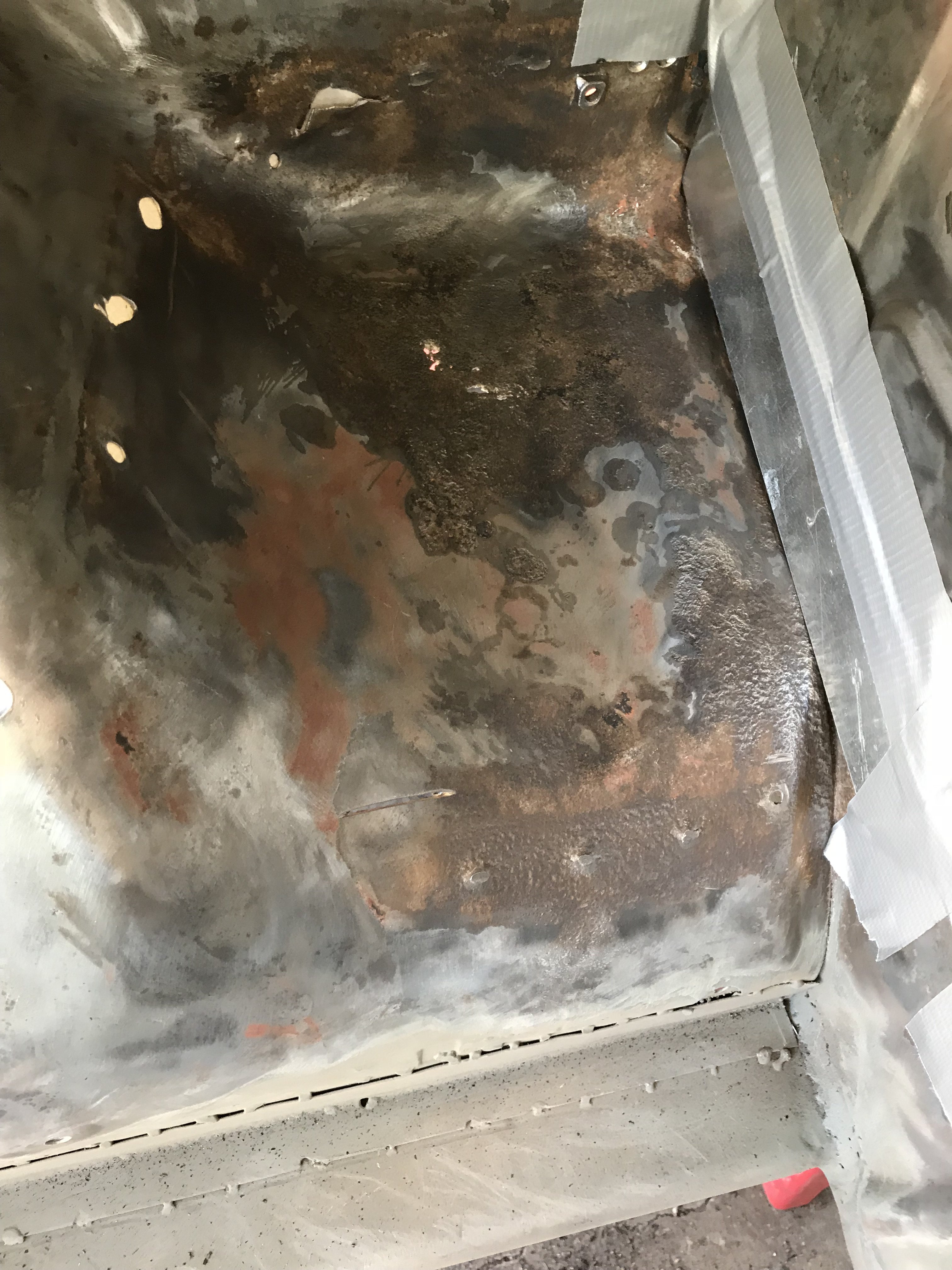
Finally got some time to work on the Z again. This is after a trip to Japan, Holiday stuff, get the scooter running and fixing the house drain pipe,
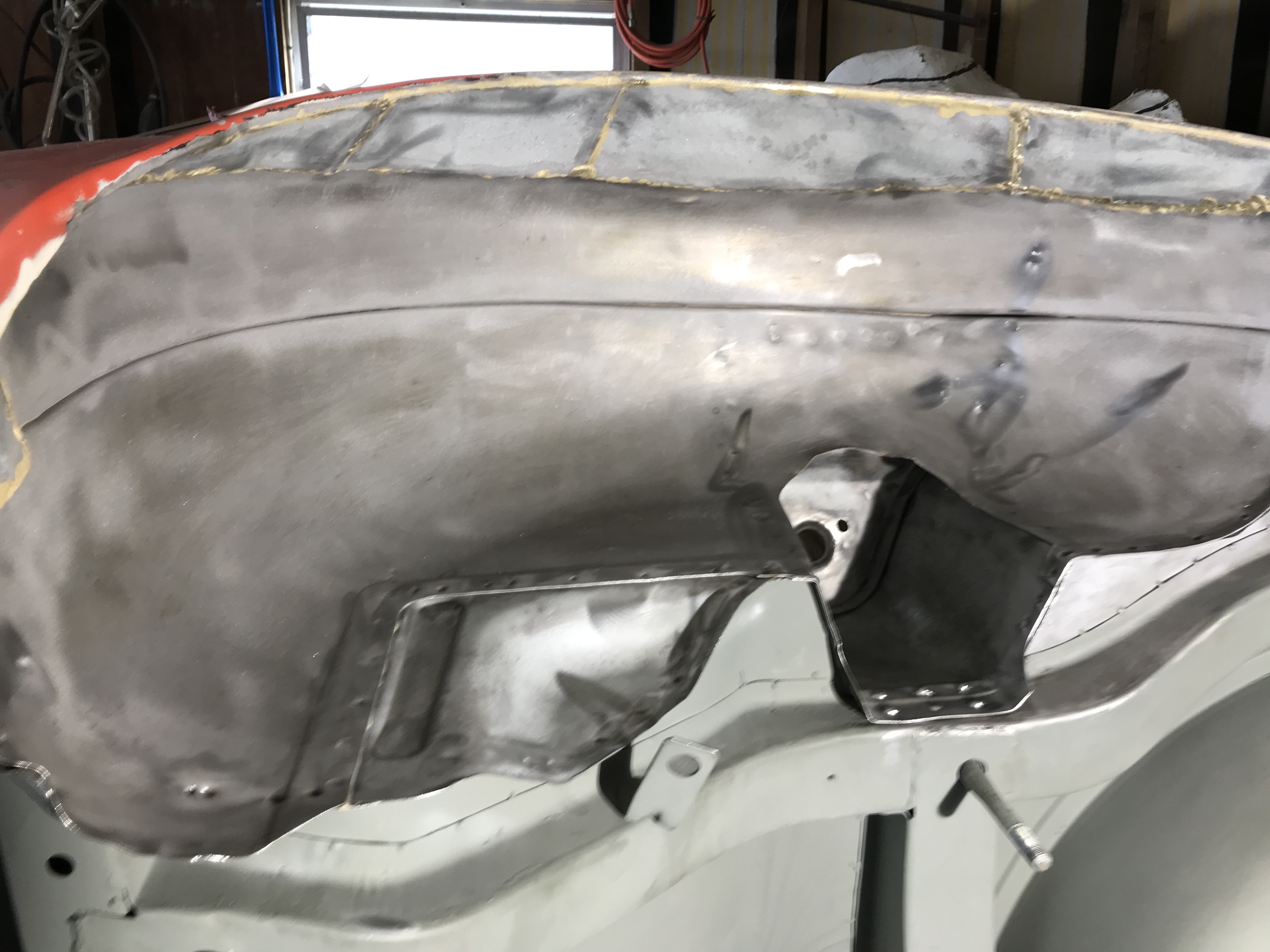
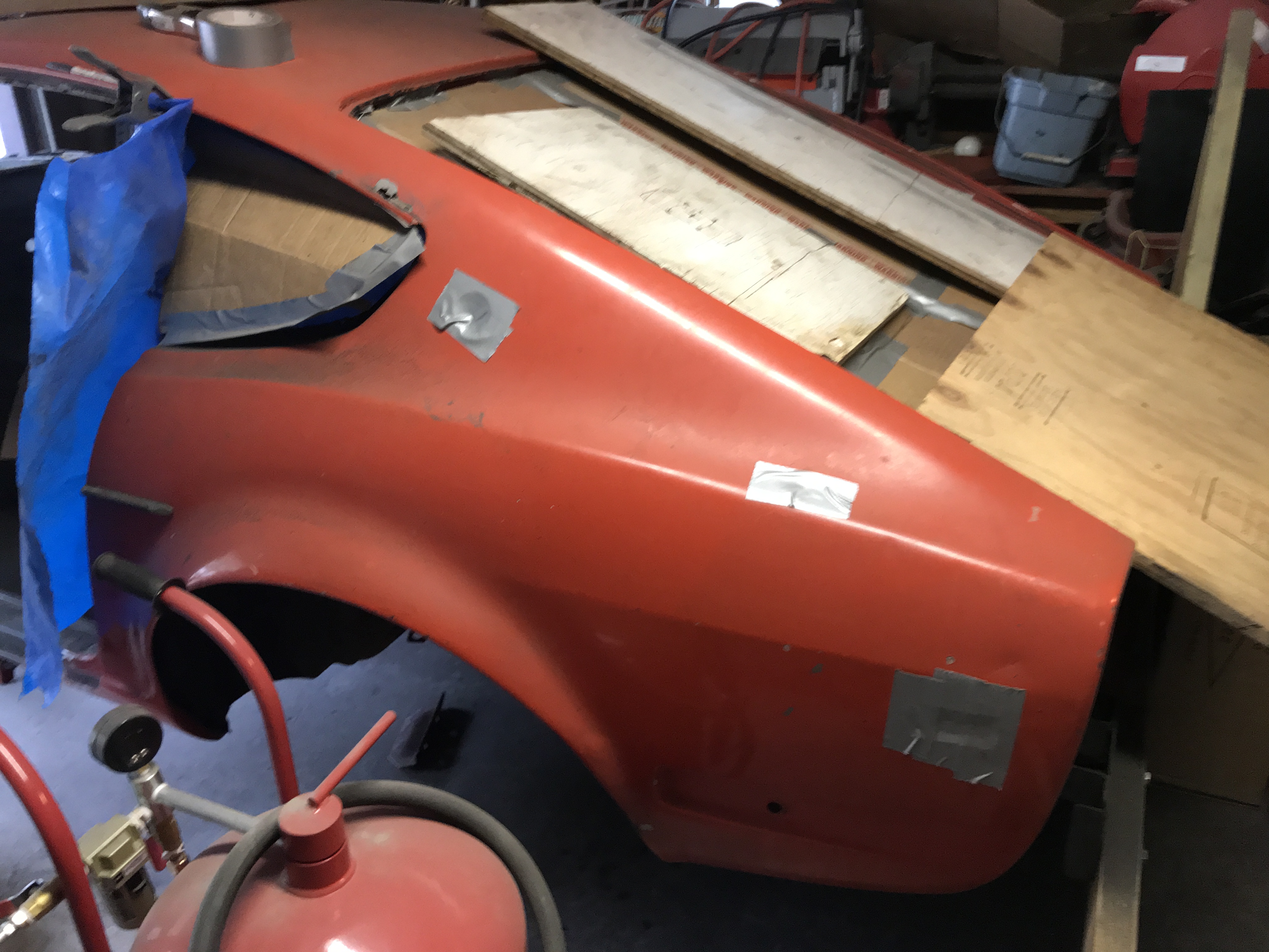
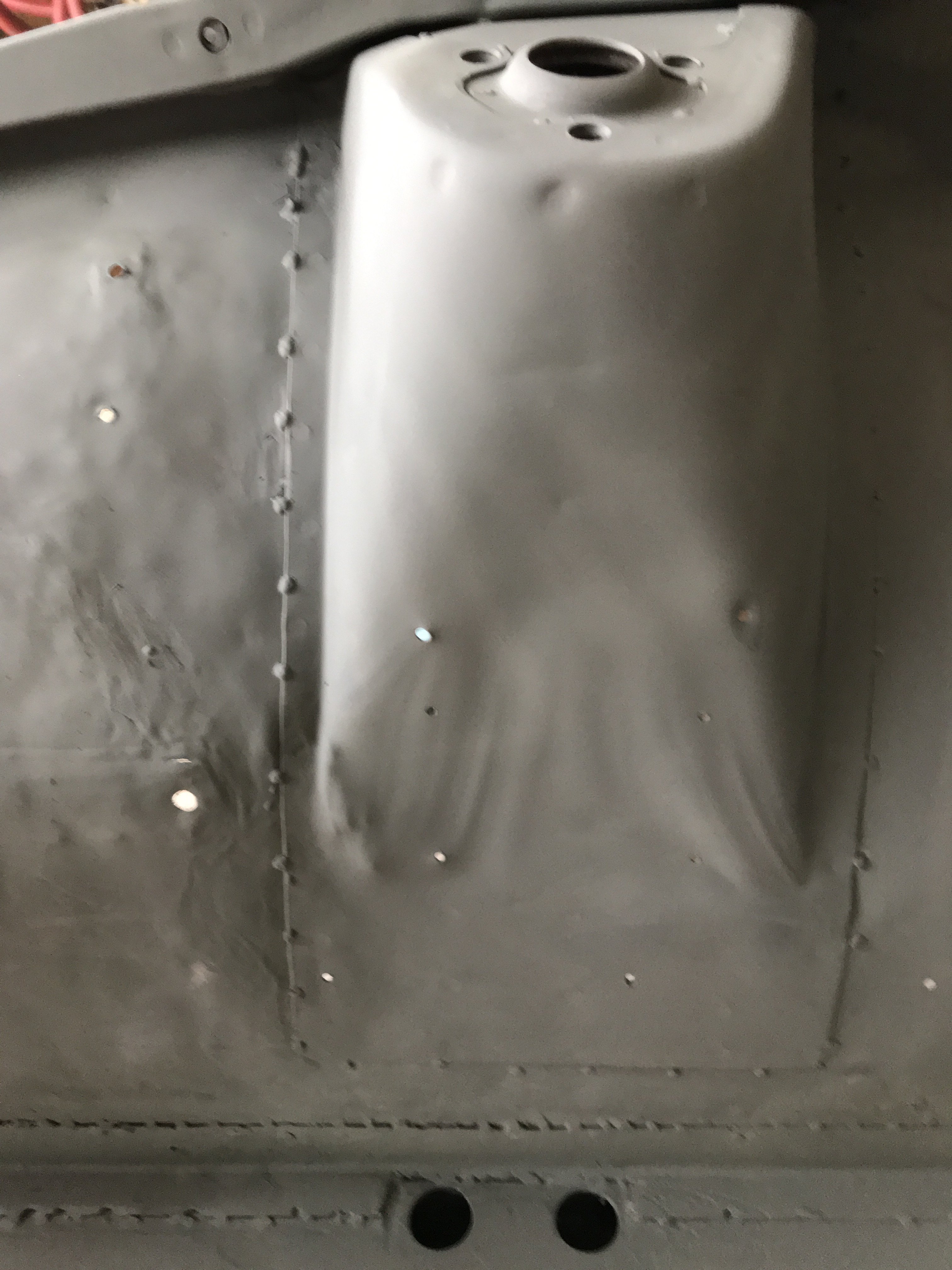
Used couple of days to remove the rest of the undercoating and paint on the bottom side of the left rear wheel well and quarter panel area.
Looking up from the ground to left/rear quarter panel
These areas were covered with thicker than factory underseal so made it more difficult to remove.
In case, you are wondering about the brazing in the upper portion of the r/wheel well- this is old( 40 years) sheetmetal extension from wheel tube
to the added metal fender flares. This area might have to be altered as the new tires might be 245/40 x 17 with 12" wide wheels and new flares
might have to be set higher.
-
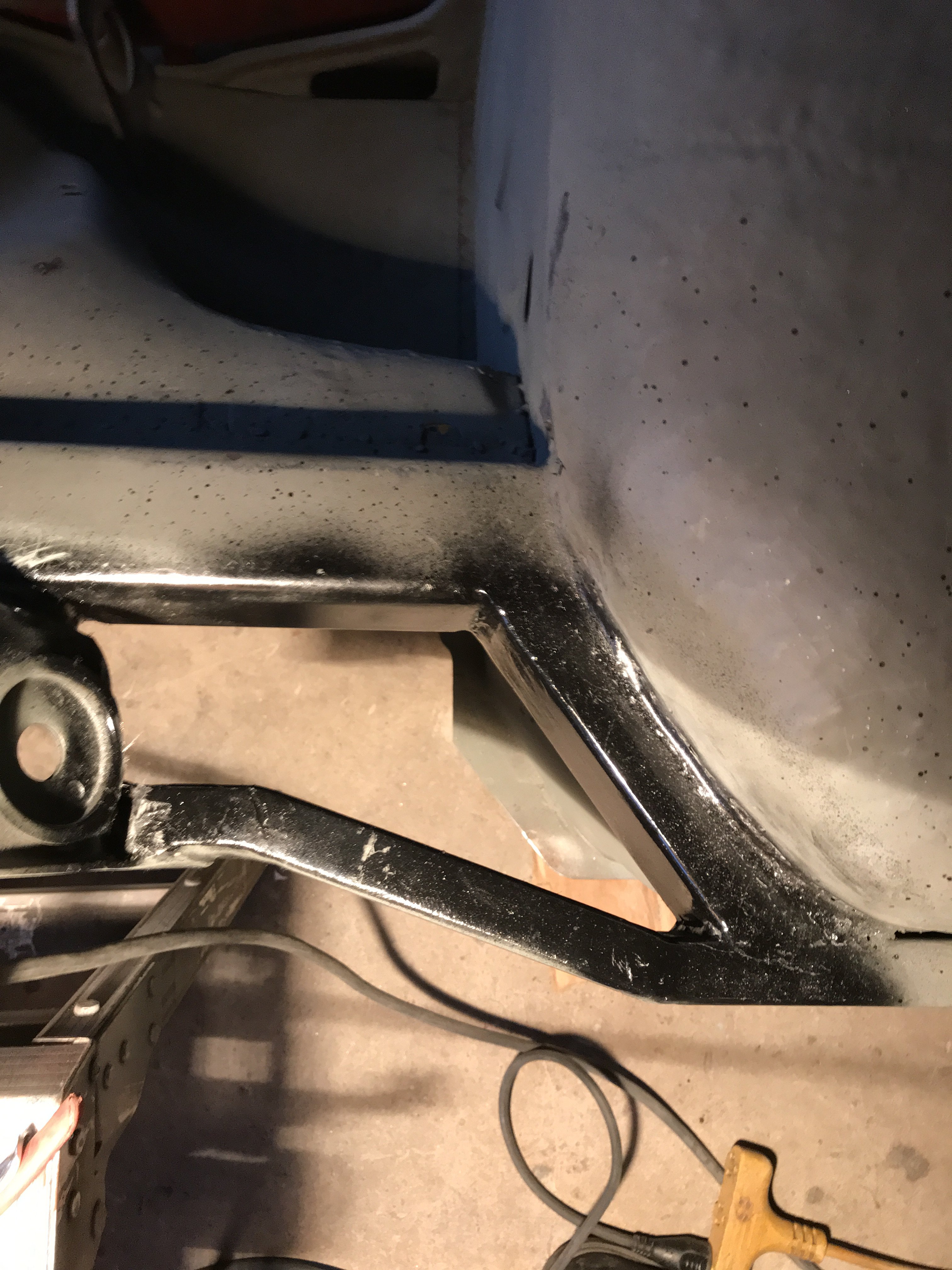
As if the Holidays wasn't keeping me busy already, I had a plumbing leak in the house to repair. But I managed to work on my car. I wanted to "box in" the tension rod support area. I painted the inside of the box with black paint. I used 16 gauge metal for the inner and outer sides of the box. The interior of these pieces were painted with weld through primer.
Then they were tack welded in place.
Then it was covered by self etching primer to prevent corrosion.
I can across a deal that I couldn't pass up. A 2013 Chinese 50CC 4 stroke Moped for only $200. It has only 10 miles on the odometer!! It wasn't running but had compression. Probably carb or ignition problem. Merry Christmas, everyone!!
-
Richard, Love to see more information and pictures of your beautiful project car when you have the time.
Sunny
-
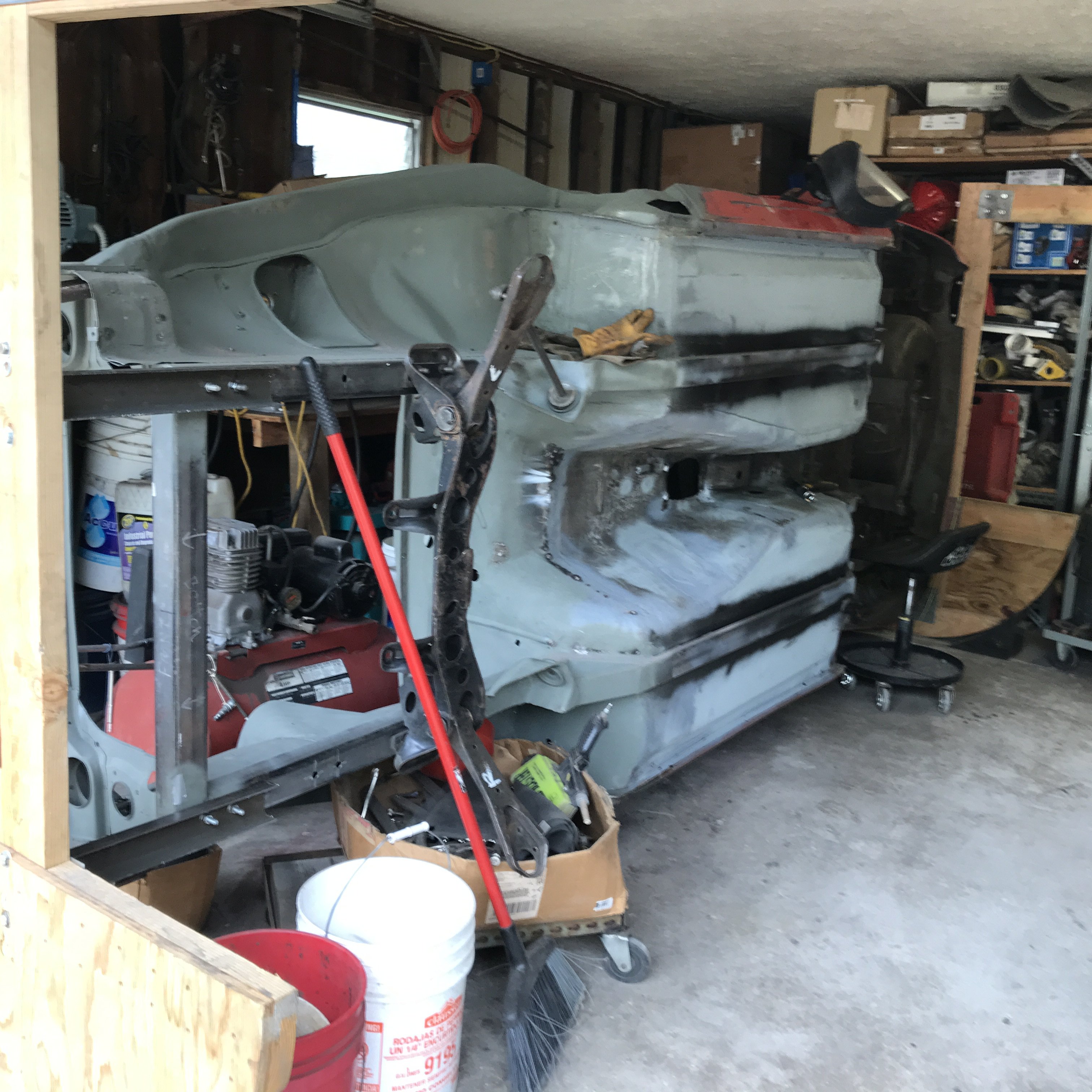
The car was p[aced on its side to remove rear undercoating.
This area is really tight to remove the undercoating. Mostly the undercoating had to heated with the heat gun then hand scraped off. The air scraper was used only on large open areas.
After scrapping was done, the 4 1/2 grinder with wire wheel removed most of the remaining underseal.
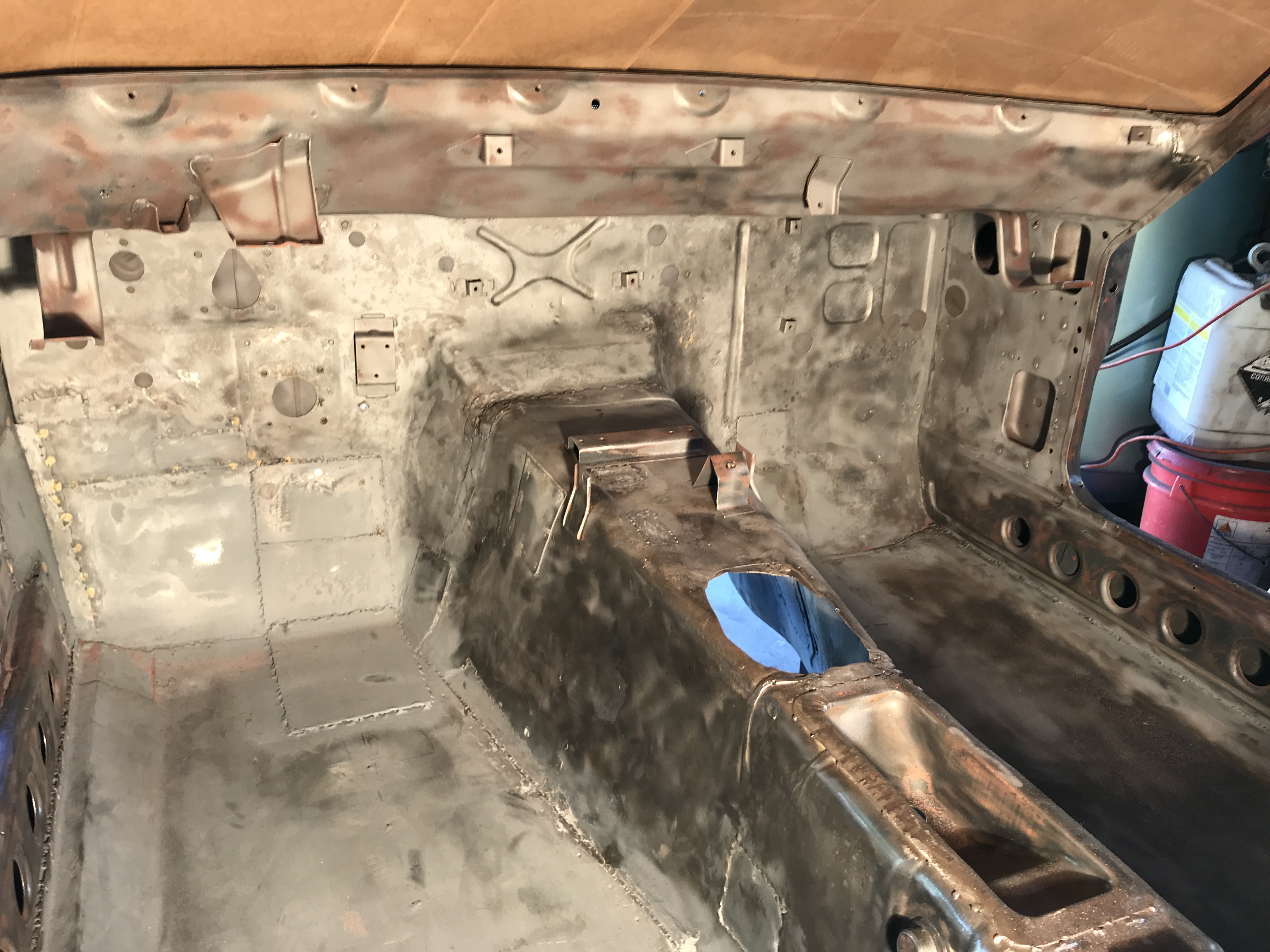
Then the area was media blasted with Number #60 grit abrasive. This media is one step rougher to remove heavy underseal in tight areas. Even so, I had media blast this area several times to do a decent job.
-
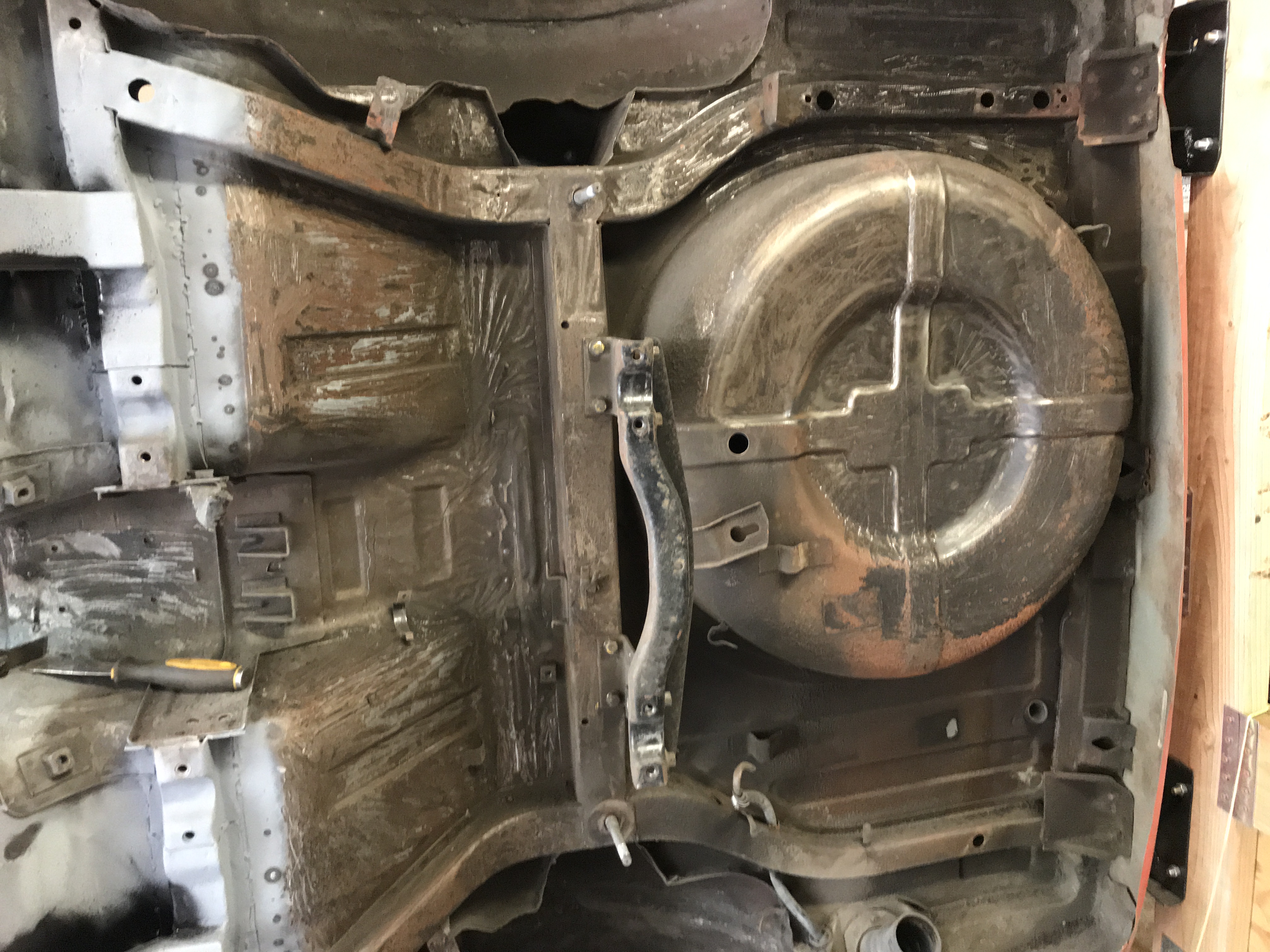
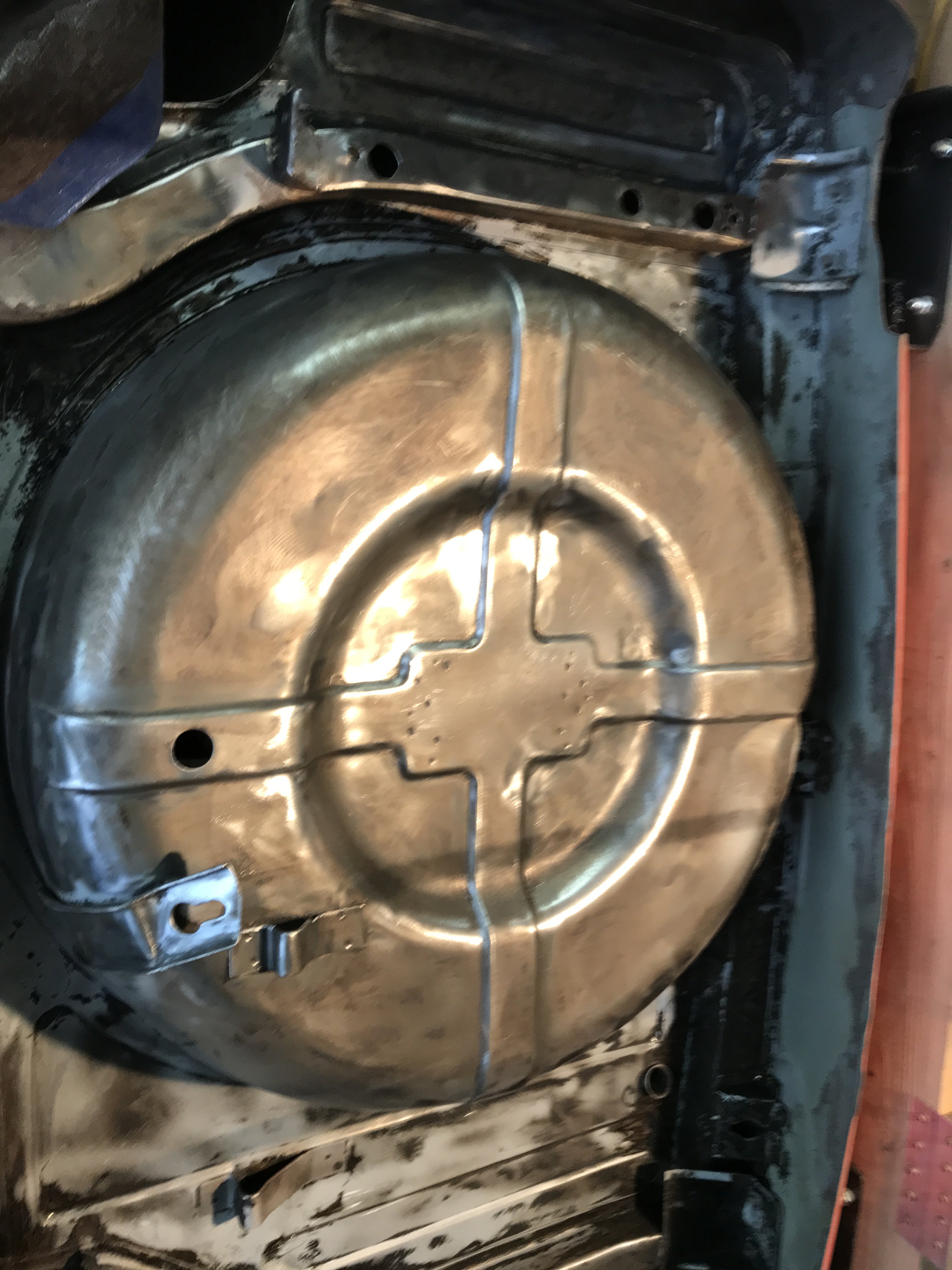
I needed more room to better job sandblasting so blocked off the front hatch area.Put a large plywood to hold up the blue tarp covering the open hatch area.Richard, the spare tire area was cleaned. Saved for now.
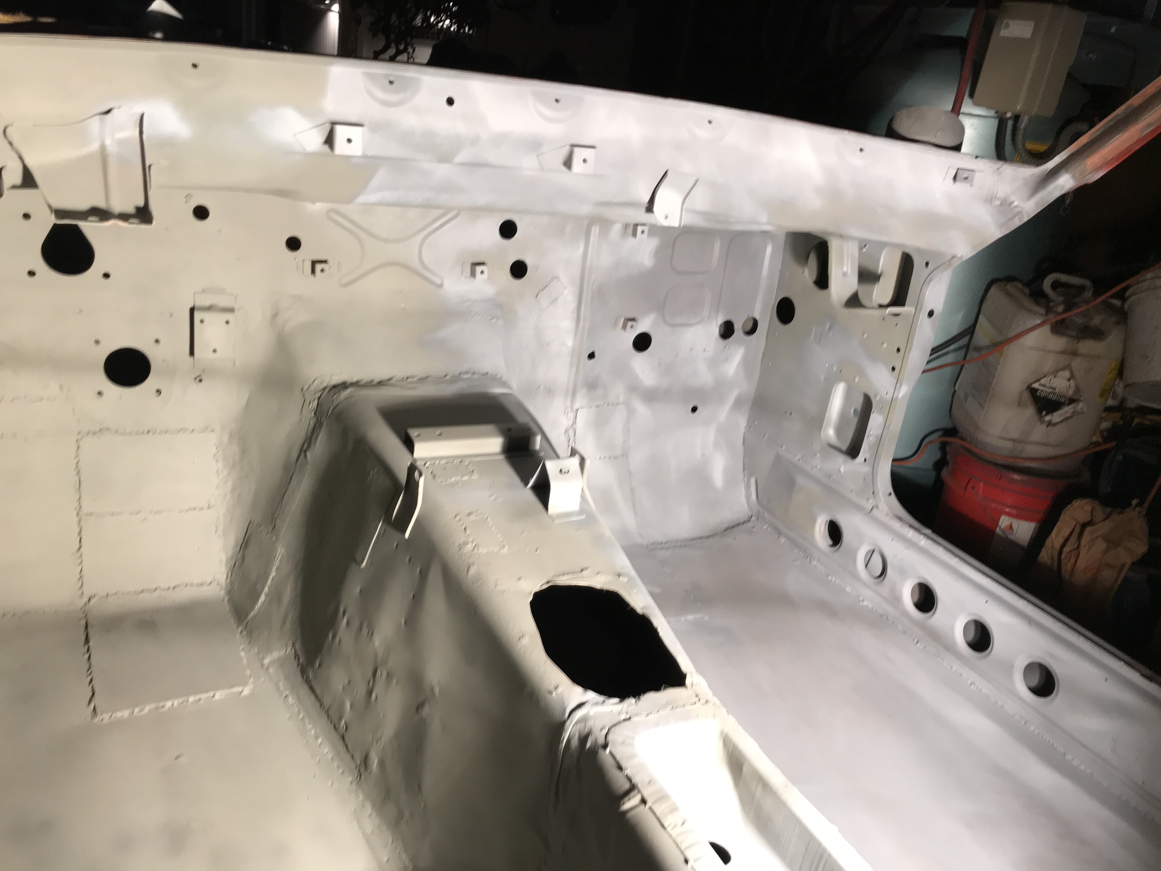
After blasting, all seams were clean out and spot welded. This area will be primed with self etching primer to prevent corrosion.
-
Hatch section was masked off carboard,plastic sheets. duct tape and plywood to control sandblasting.
Used a plywood sheet to lay down on to do the sandblasting. It was tight and hard to move around and blast.
After blasting, still more cleaning necessary.
I haven't decided about the tire well yet. But am leaning to remove it and replace it with a fuel cell.
-
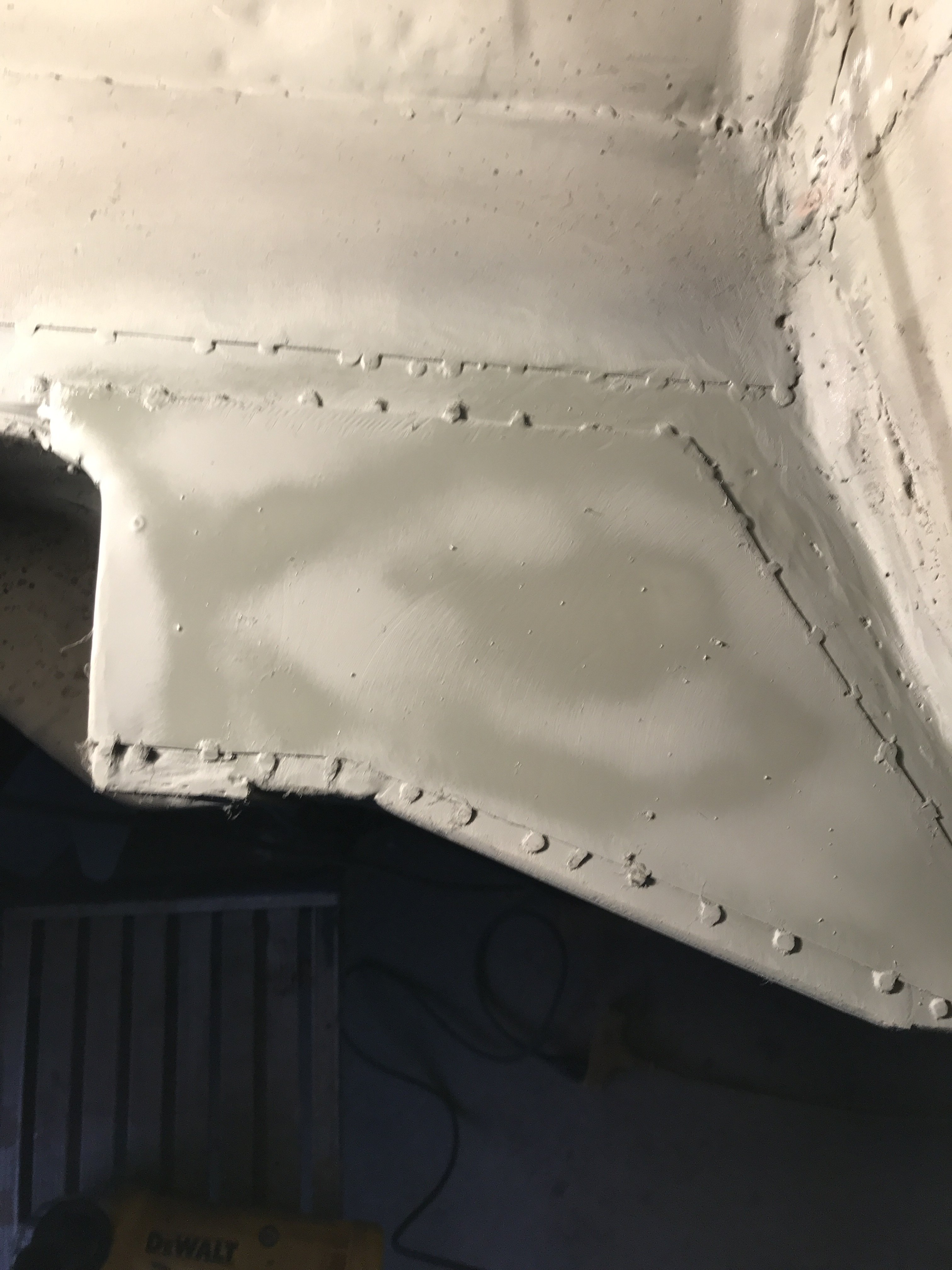
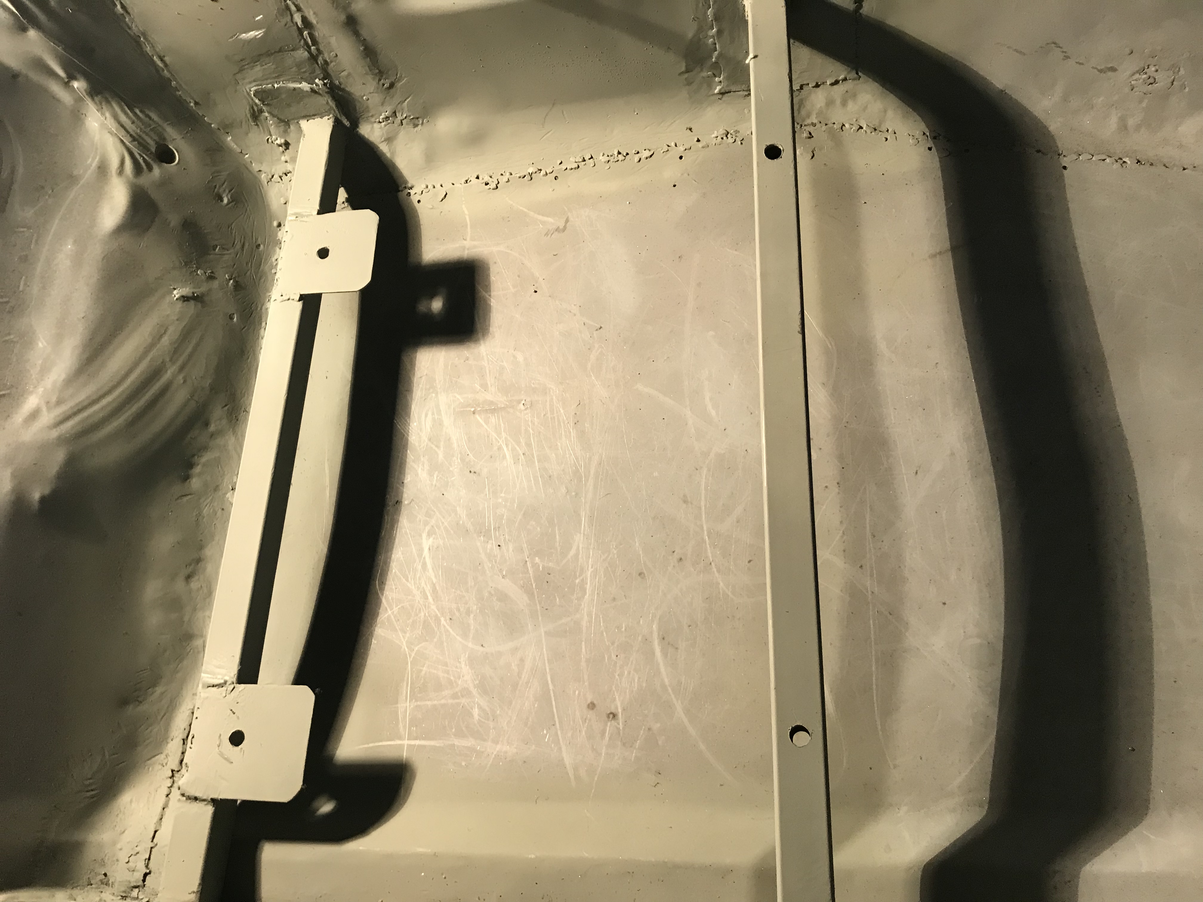
Decided to beef up the seat mounts and keep them off the floor to prevent corrosion. I utilized 1" square box tubing with reinforcing plates on each end.
Even if I go to different seats, these mounts should be a good base to start with.
driver's side mounts passenger's mounts. Thanks Richard, most people don't realize how much work is actually involved in this type of build.
-
Tools used for undercoat and paint removal The Veteran Day holiday provide me additonal time to work on my car. I tack welded
all of the seams in and out of the engine compartment,
Strut tower also welded,
A 4 1/2 electricgrinder with twisted wire cup brush was used befotre blasting. The interior of the car masked off so the compartment could be media blasted whjile keeping most media inside the car. All open holes in firewall were masked off using duct tape. The windshield area was covered with large pieces of cardboard. Canvas and plastic sheeting covered doors and hatch areas. Face respirator and face shield were used when media blasting. In this case, 80 grit abrasive was utilized. I used a large wet/dry SHOP VAV to recover the media and reuse the media. A wire mesh filtered the recovered media before reusing..
self etching primer applied to prevent corrosion, The 16 gauge plates above the frame railings reinforce the floor panels.
-
One of the reasons that I went to the SEMA Show 2017 was to check on the latest
LS motors. This motor is the LS376/480 the updated version of the LS3. It basically has a cam change. the motor produces 495HP and 473 ft lbs of torque. Perfect for me.
.This Chevrolet High Performance manual has all necessary part numbers to
build and install their motors in almost any car or truck. It gives even measurements for engine and its accessories(air conditioning,power steering,etc).i
-
Back to the Build.
wire brushed the cowl area but vent must be removed to
clean area around vent box. So vent cover was carefully removed.
After cleaning , area was primed with self-etching primer to prevent rust before media blasting.Driver side cowl after priming.
Vent cover after sand blasting and painting with weld thu primer
-
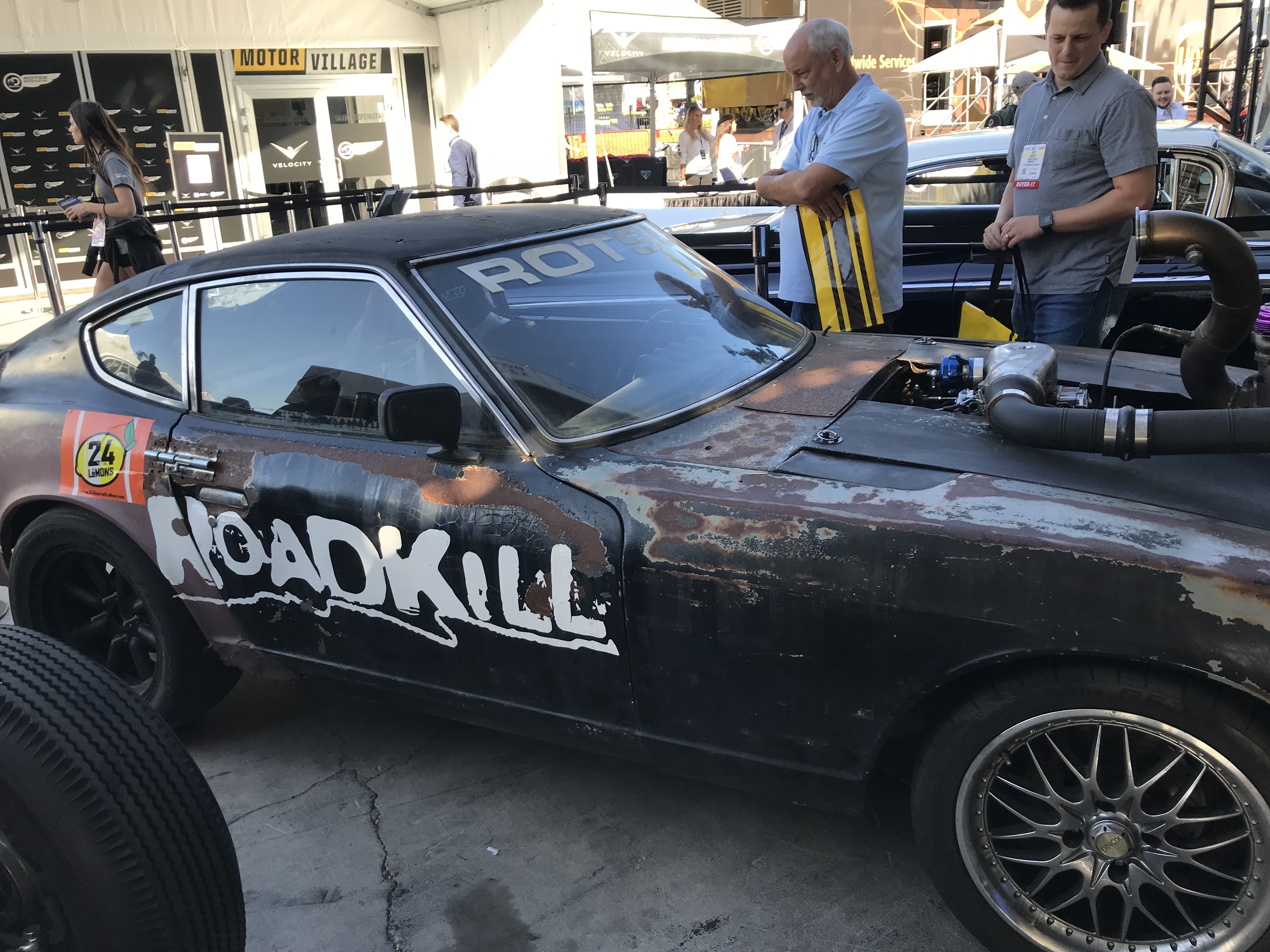
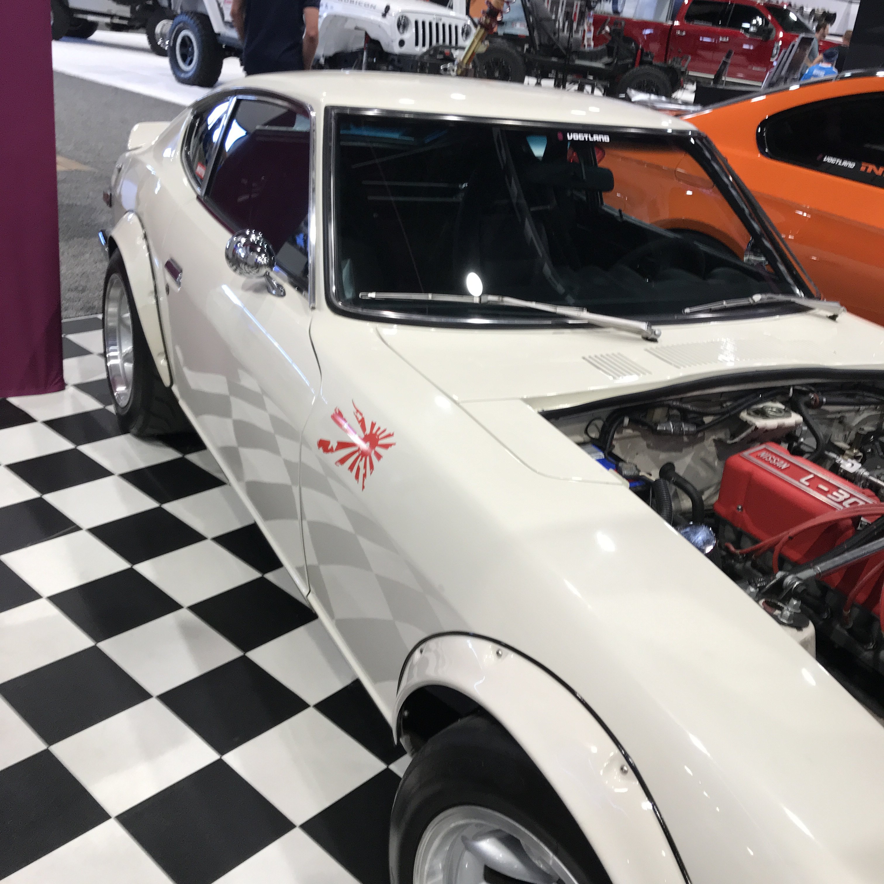
IMG_1912.MOV Just returned from the SEMA SHOW in Las Vegas. The ROAD KILL 71 240Z with Mustang 5.0 with Ford truck turbo blowing thu Holley carb.
Low budget build but with a lot of fabrication work.
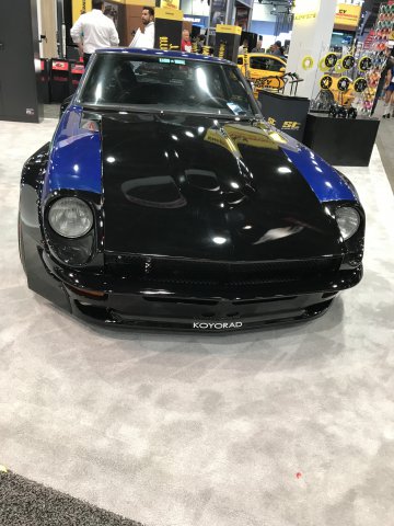
A clean Z car with fender flares
E we
Bored out motor with Weber carbs
Wide flared 240Z car. Someone told me that there was a early Z with a Skyline twin cam motor but I must have missed it. There were hundreds of cars and trucks to see at the show.
-
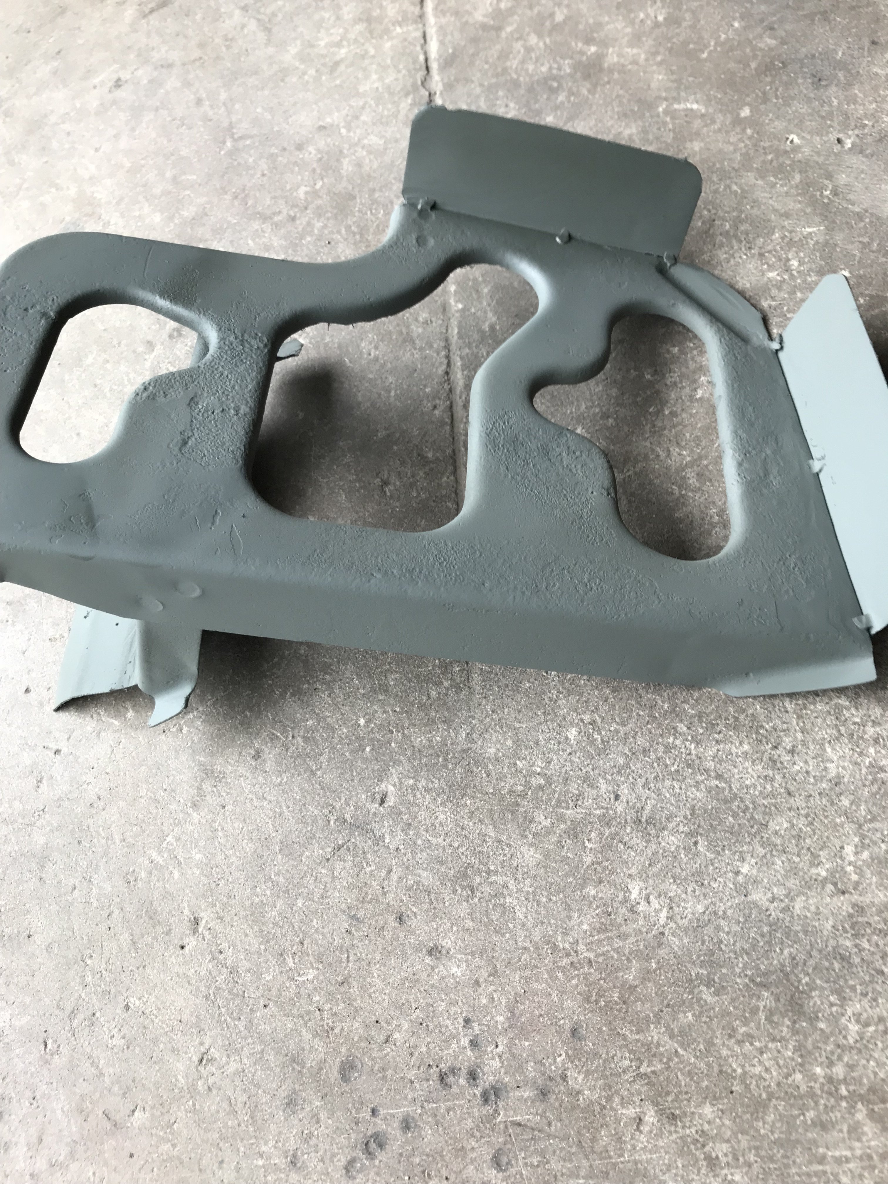
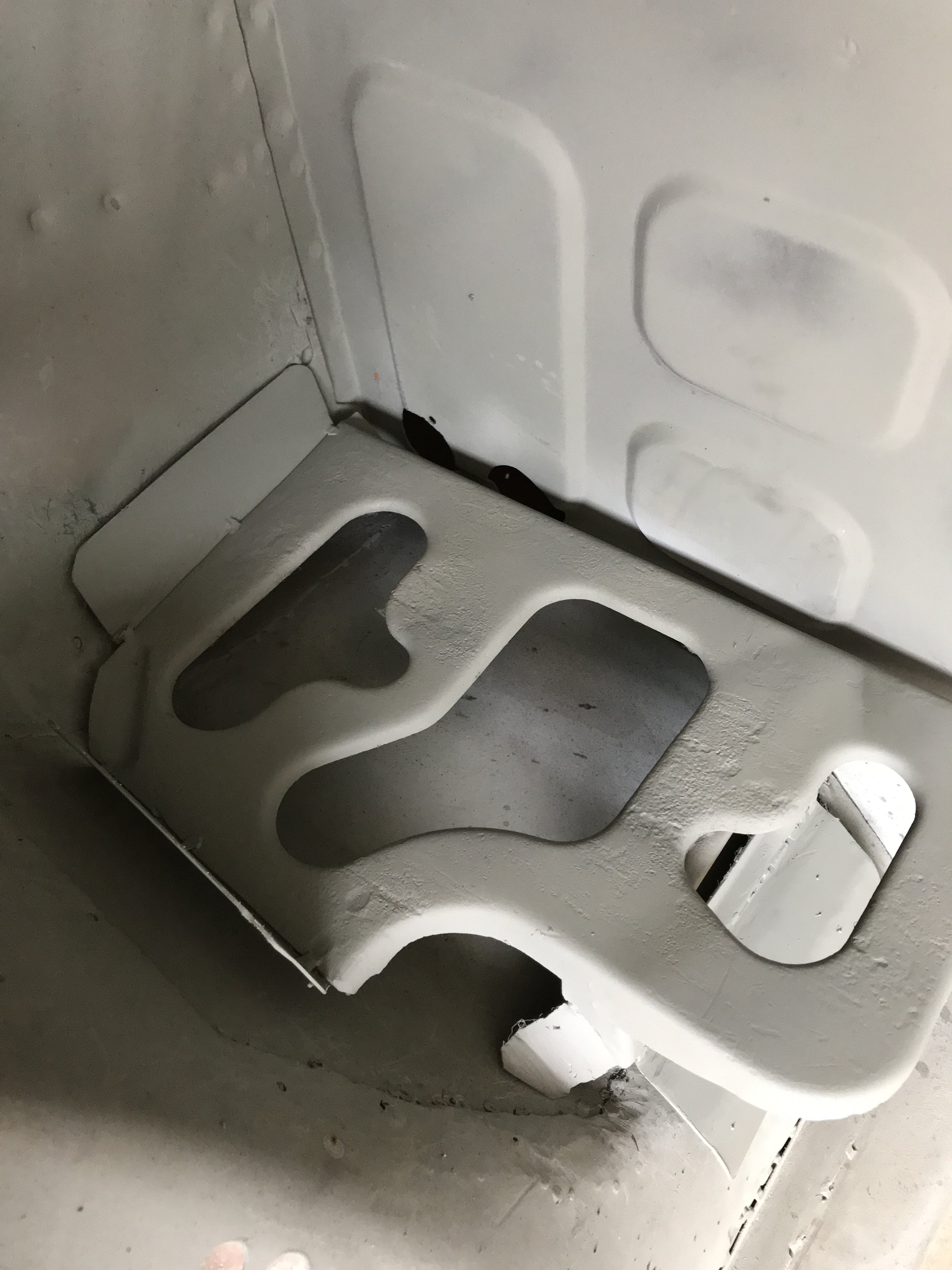
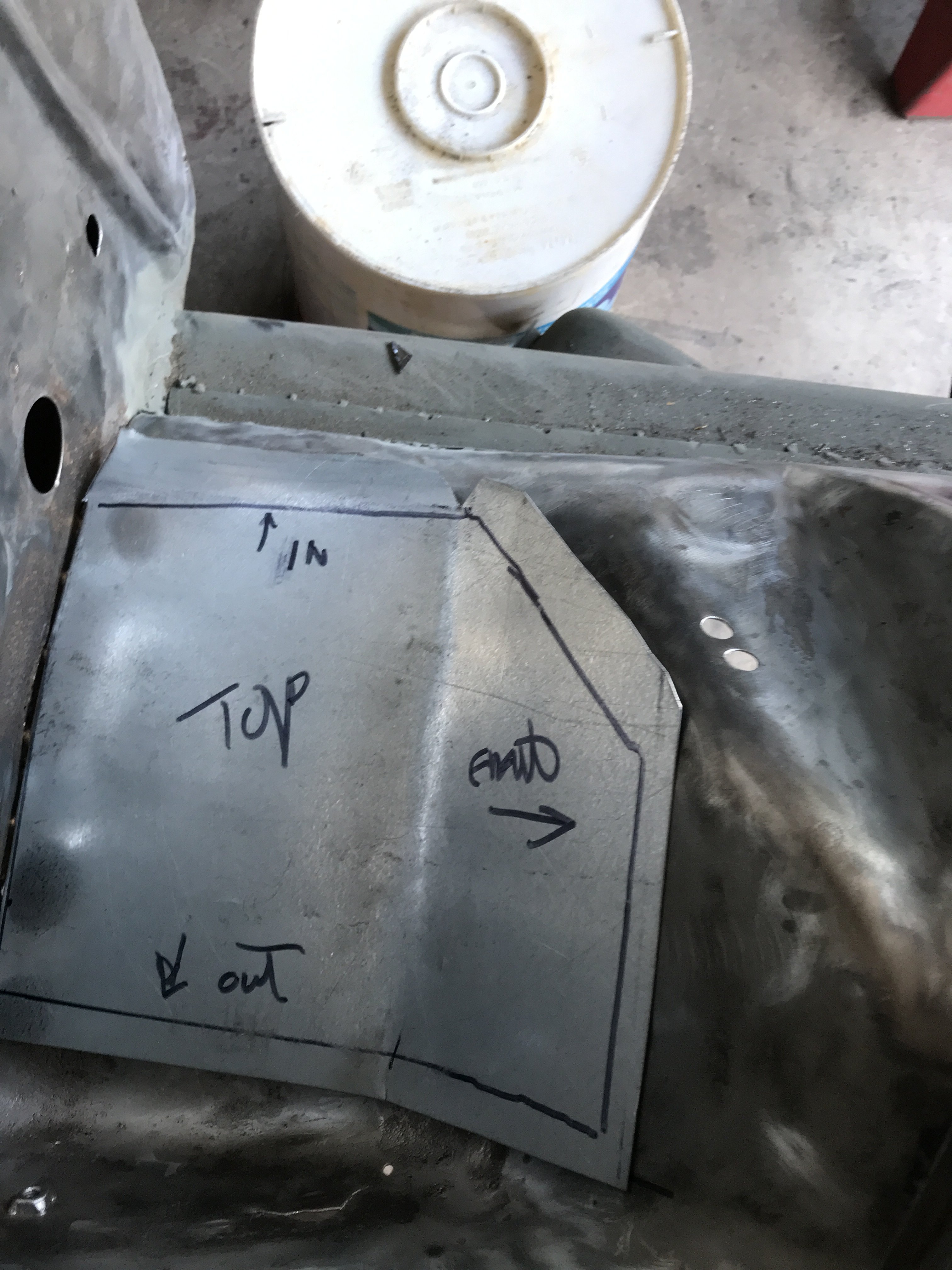
First pic is top view of restored battery holder. Second is the bottom view of the holder. The third pic is the battery holder "test fitted". I still have not decided whether to
install the holder or a marine type of battery box in the rear of car. The last pic is the firewall after I plugged unnecessary holes.
-
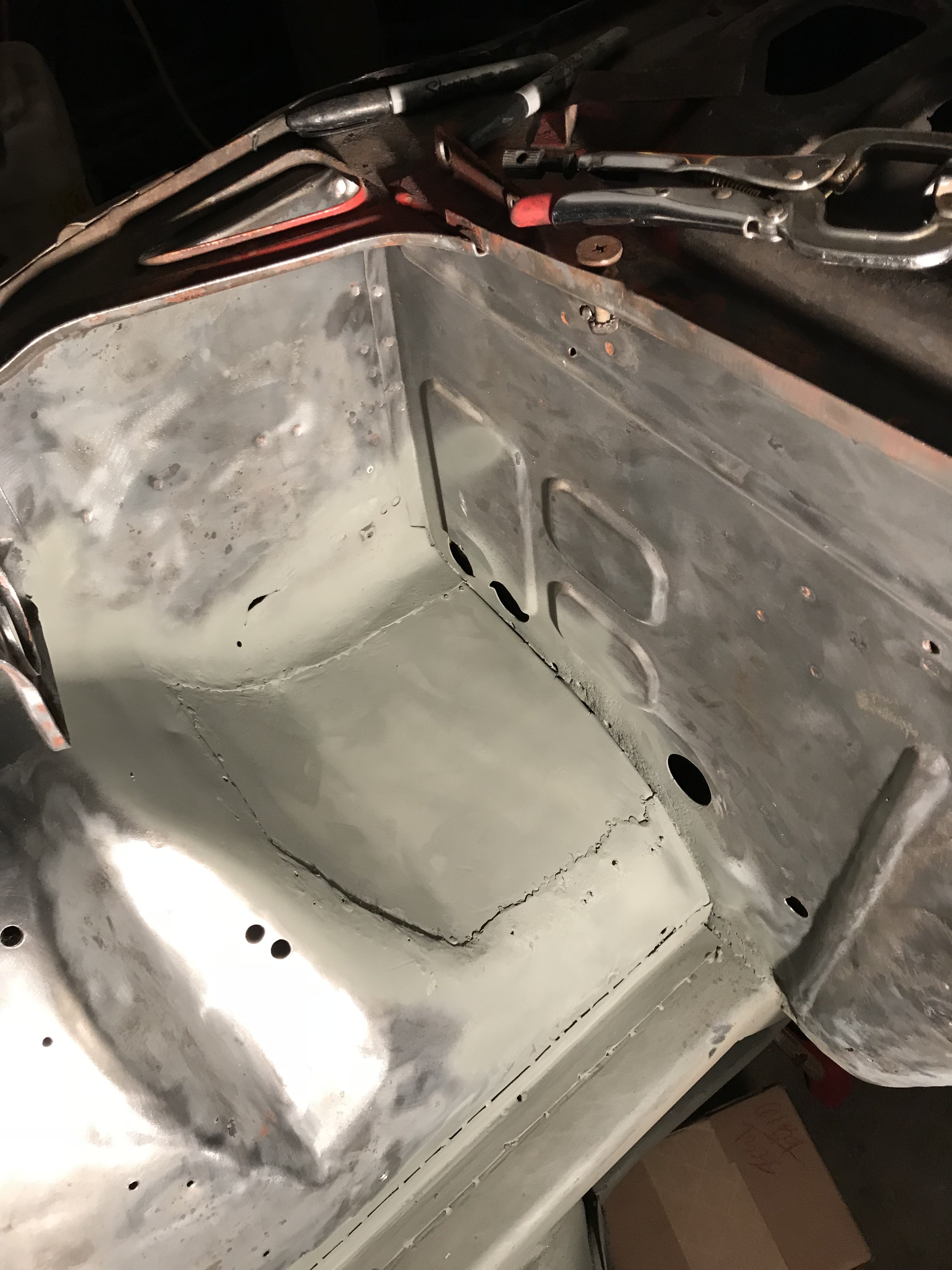
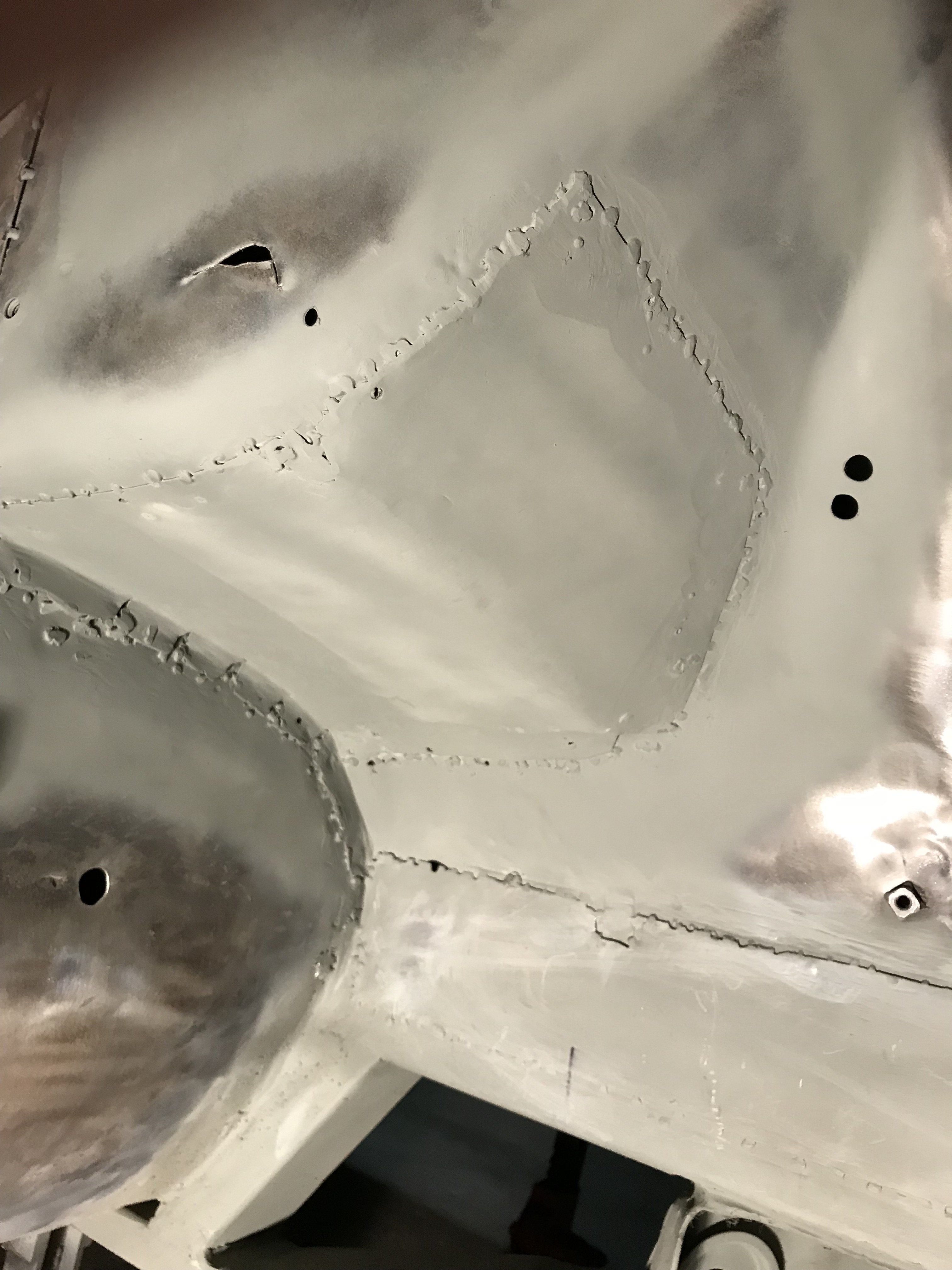
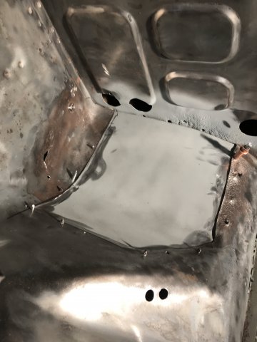
First picture is the top view of the patch welded in. Second pic shows the bottom view of the patch. I have not decided whether to reinstall the battery holder or relocate it to the rear of the car.
-
Patch had to be held in place with Cleco clips for welding. Sheet metal screws were also used.
Quote
-
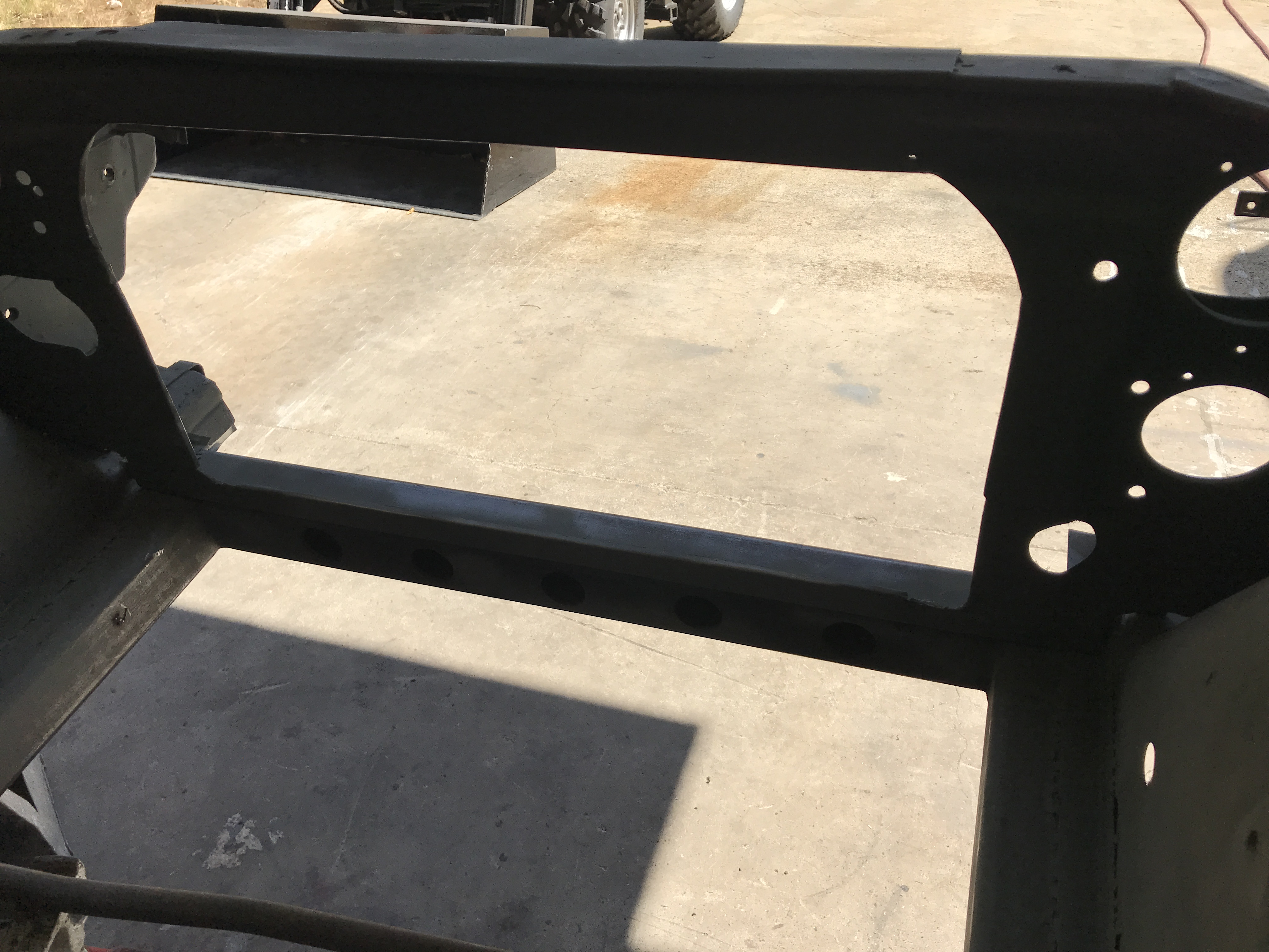
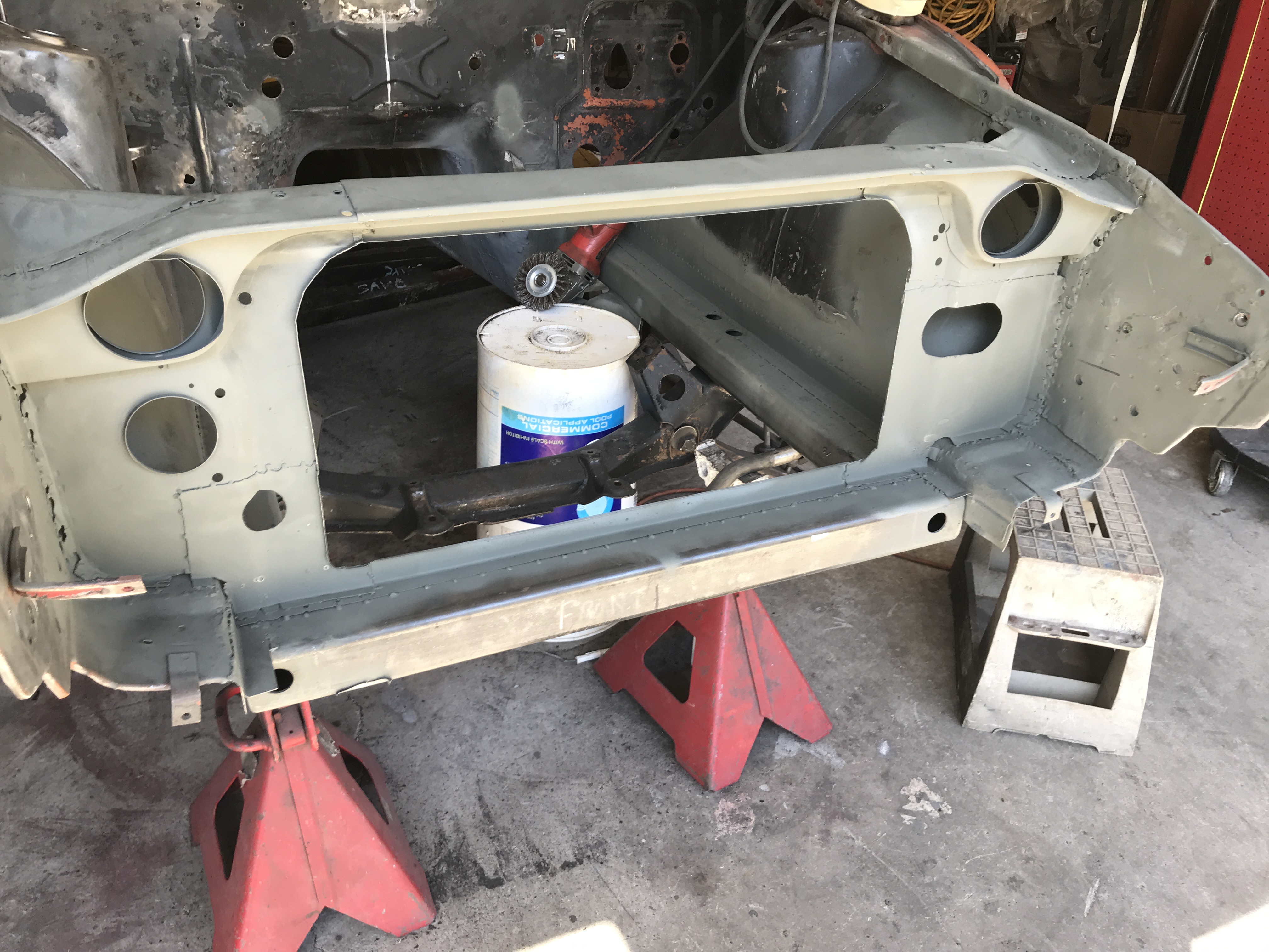
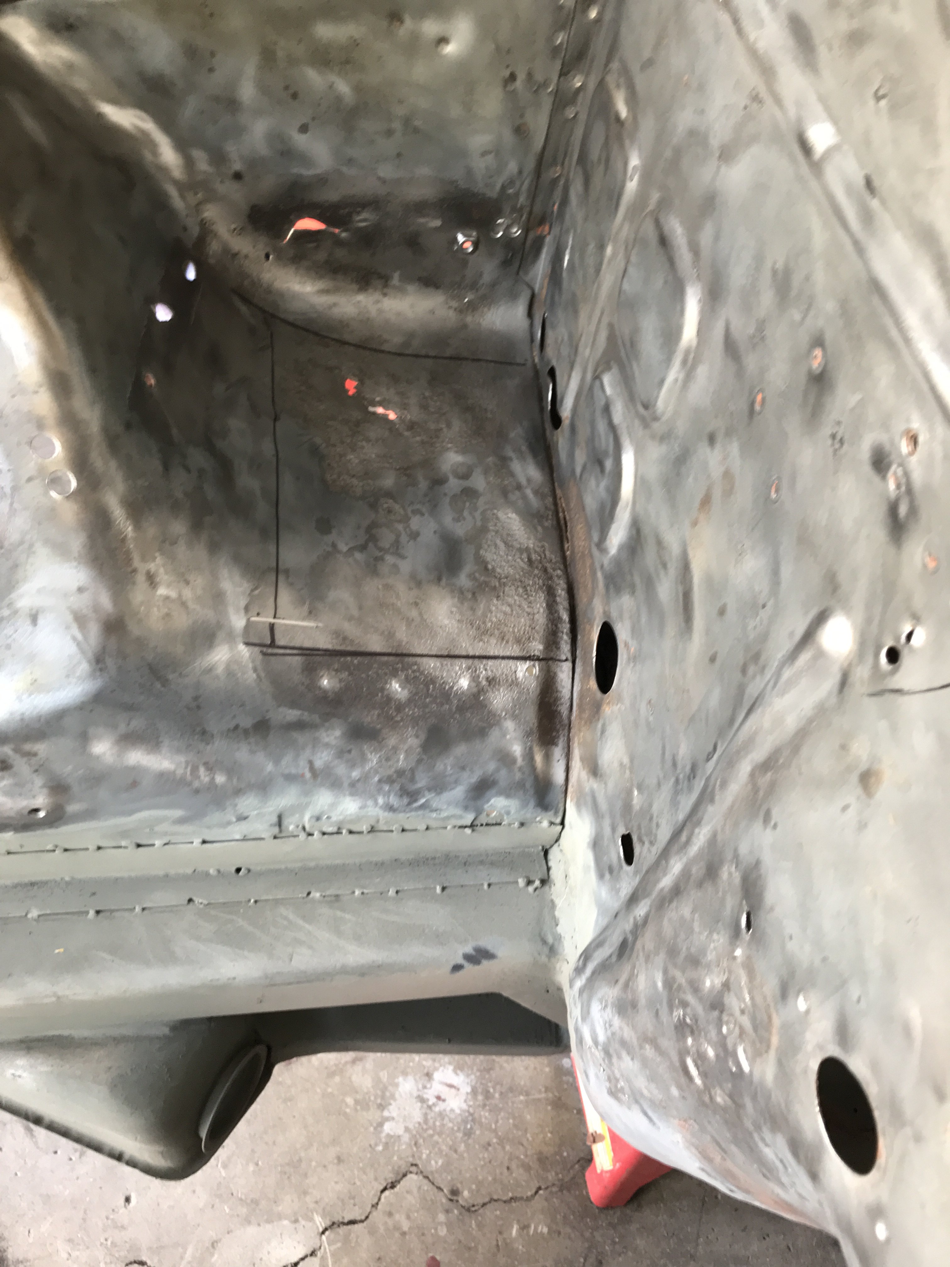
First picture is the completed radiator core support. It is welded to both sides of the front fenders and to the square tubing frame. Picture 2 show the rear of the support.
I drill holes in the inside of the front tubing to lighten it and for looks. The third picture shows the front area where the bumpers and hood hinge are located. Spacing of core support and
hood hinges are critical to prevent interference of moving parts. Check clearance before welding support in. Next step was to strip the engine compartment and weld up any small
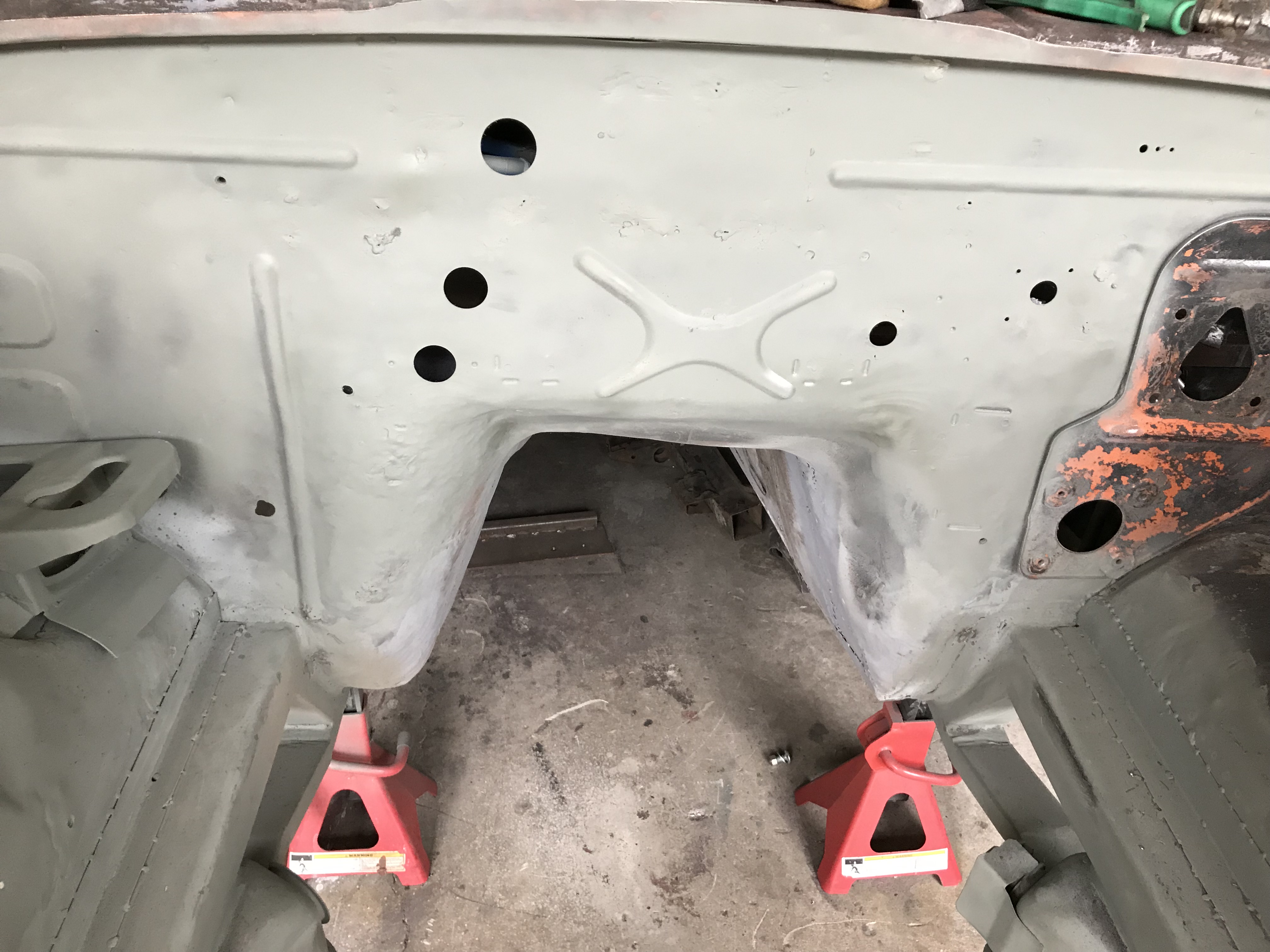
unnecessary holes. But I discovered the area under the battery holder was corroded. So the holder was cut out. Photo 4 shows the corrosion. Pic #5 is corroded area is to be cut out. The last pic is the top view of the patch to be installed .

 The outside test strip indicates outward airflow also.
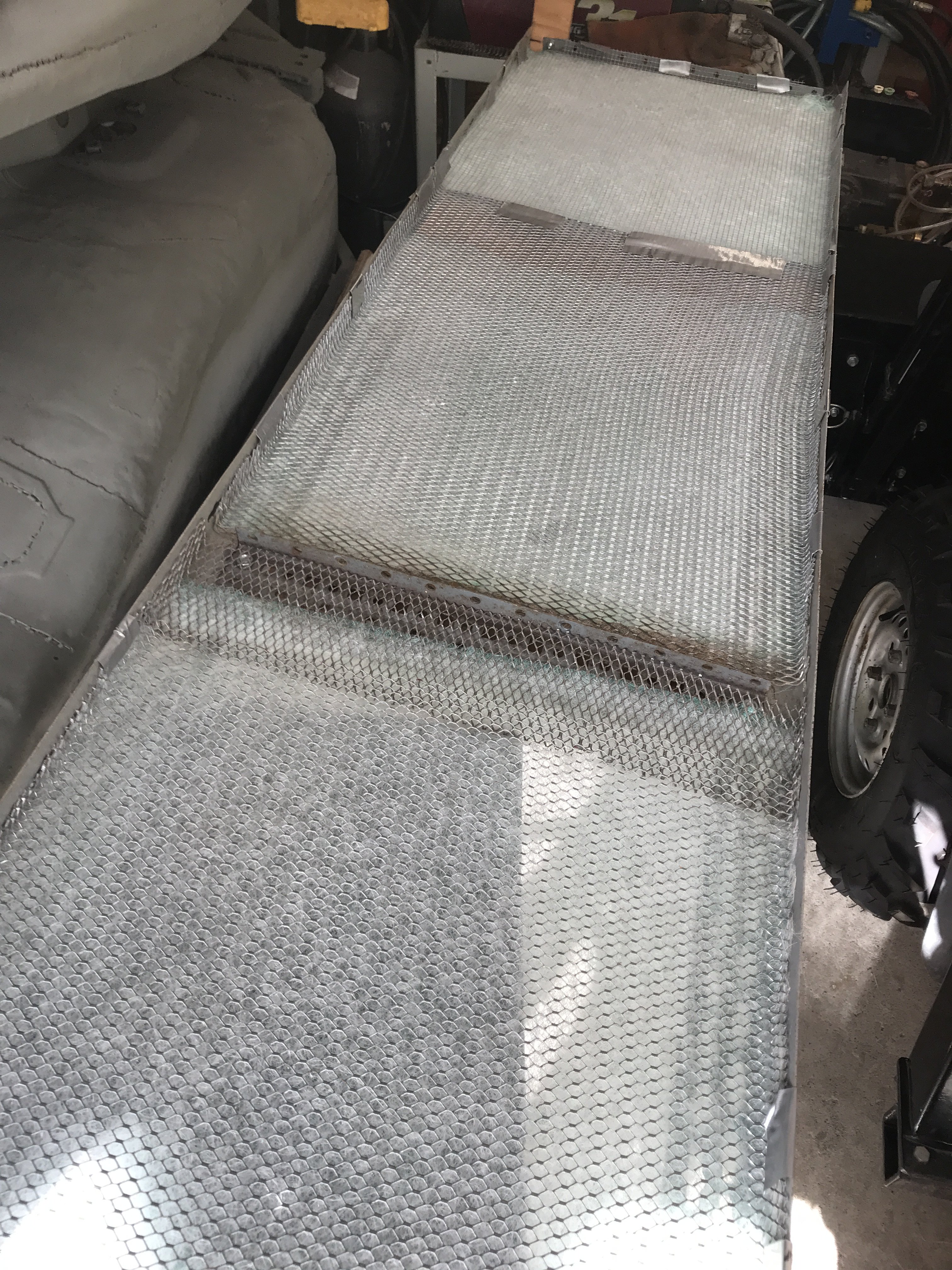
.JPG.fbd6430e2d451e6cf77eeb526bf708b5.JPG)


 Right front side of booth
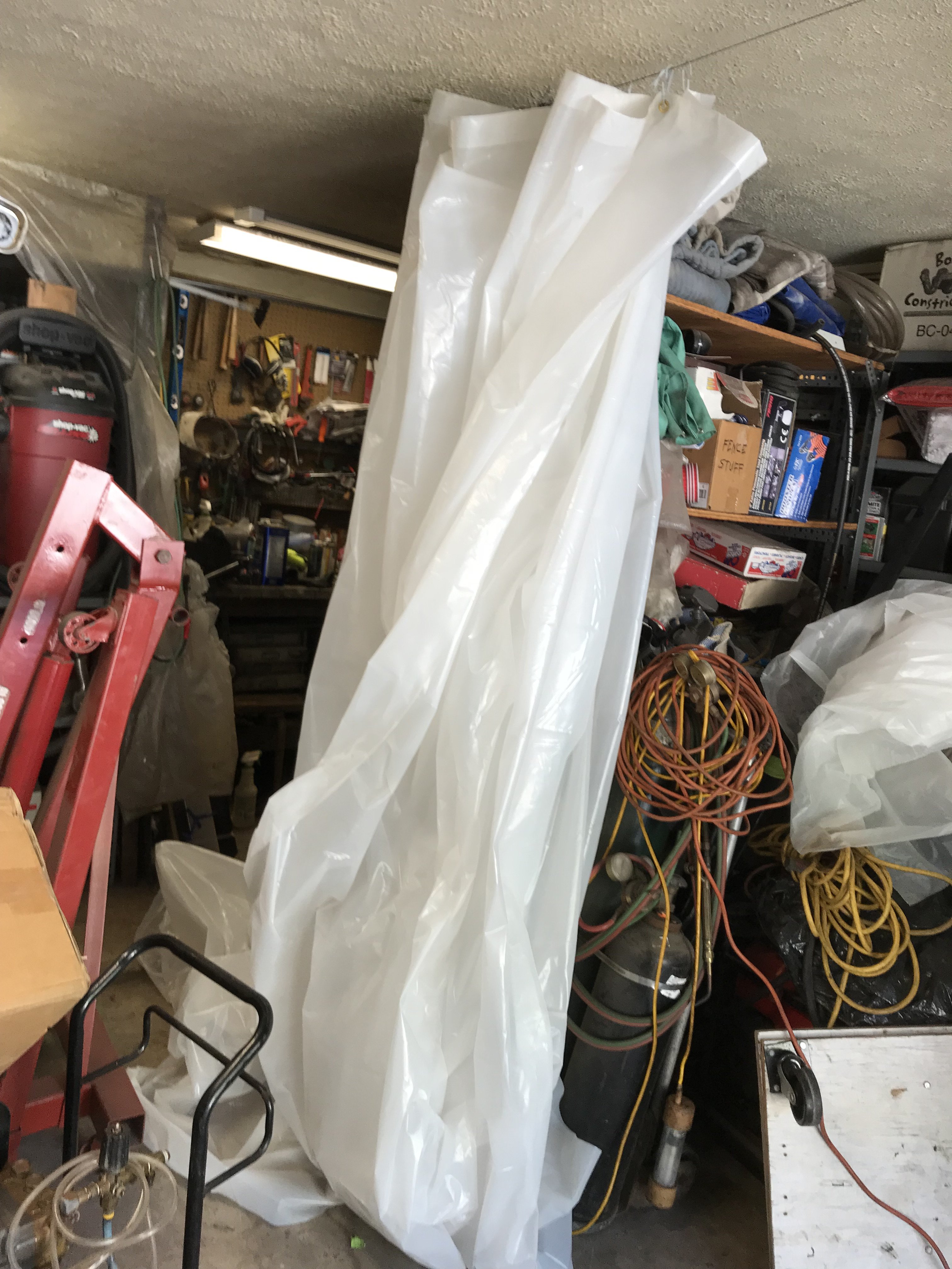
 The rear and right side booth walls assembled.
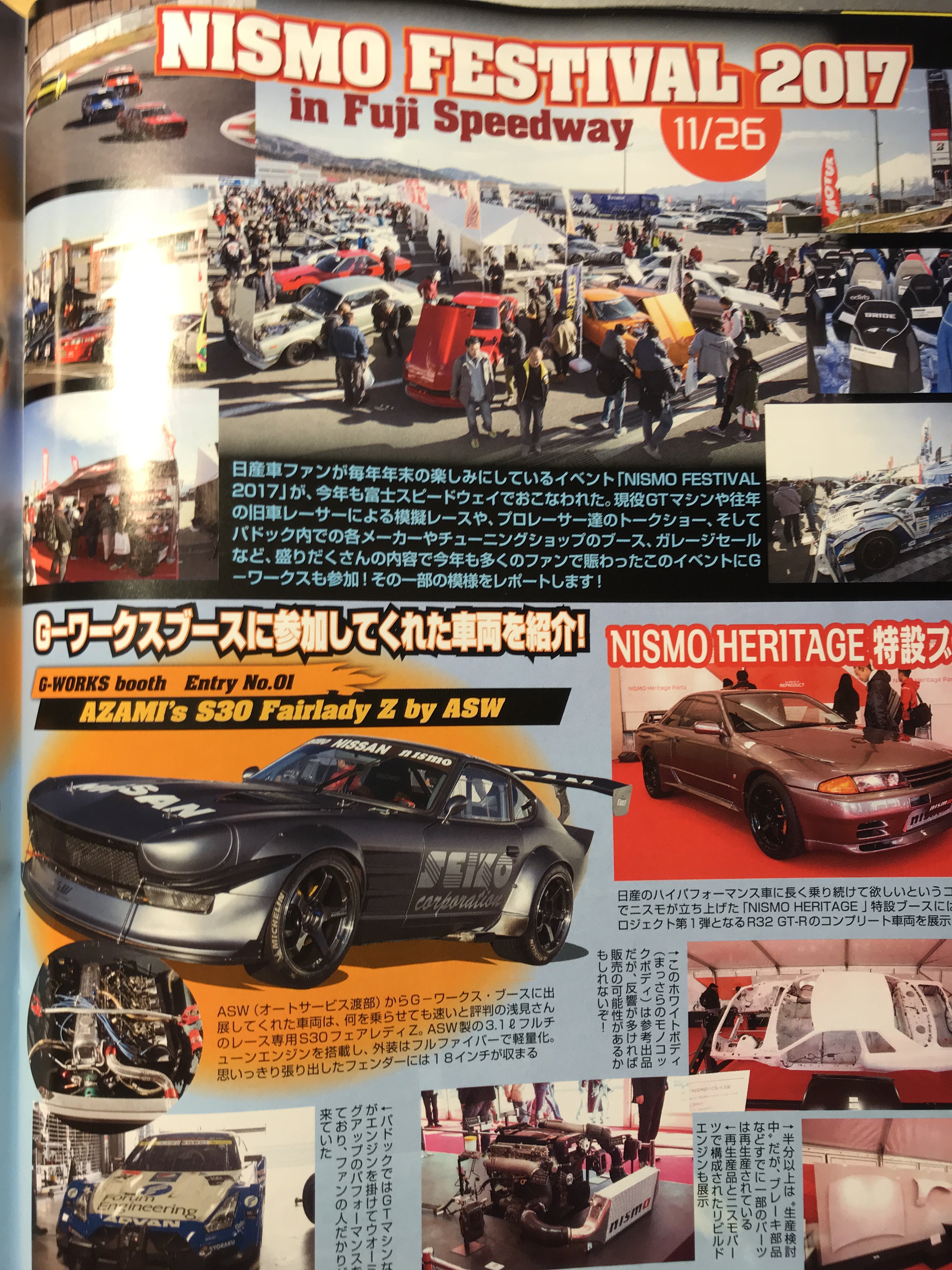
 Drifting is very popular in Japan. Probably because it does not
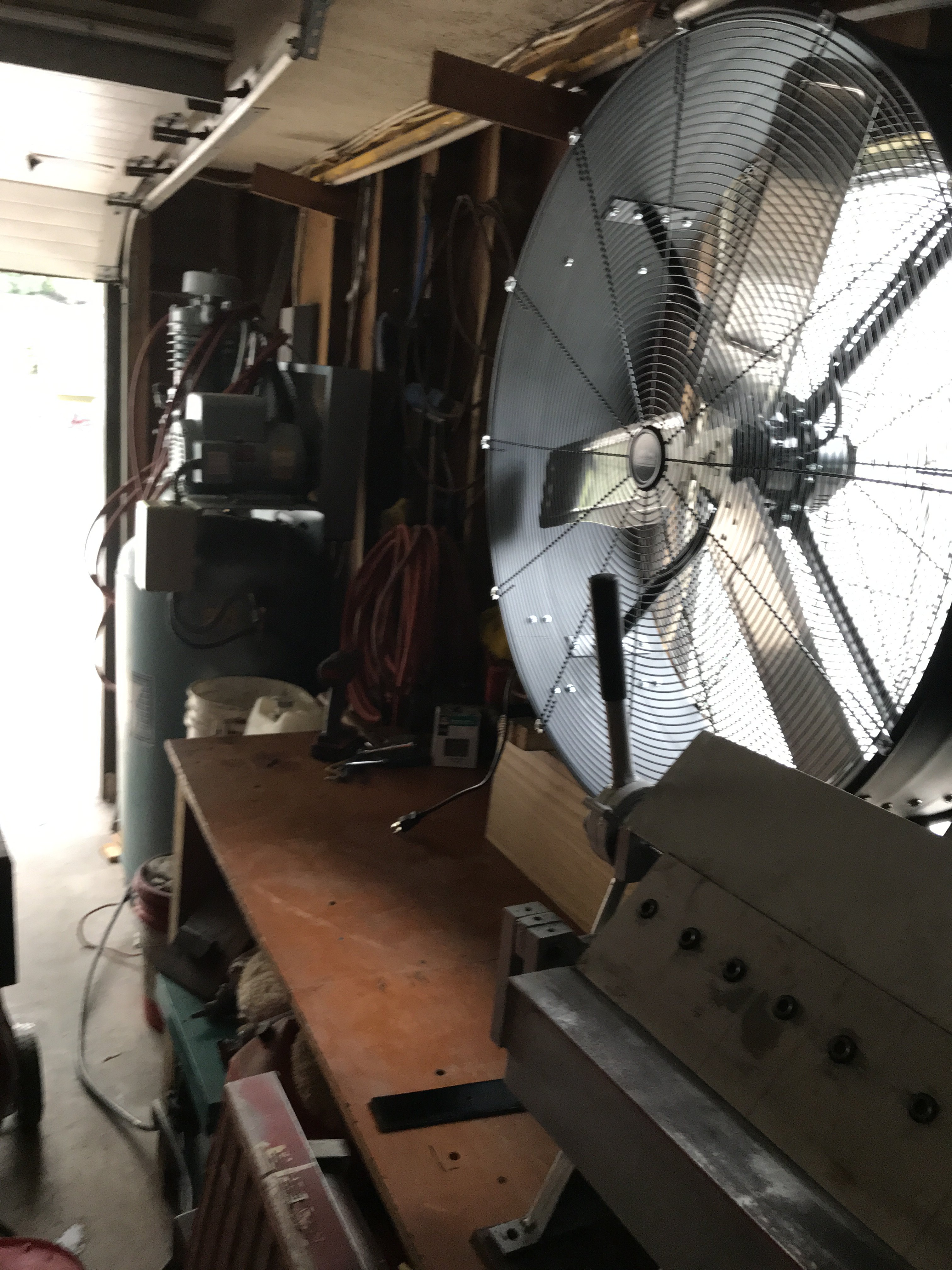
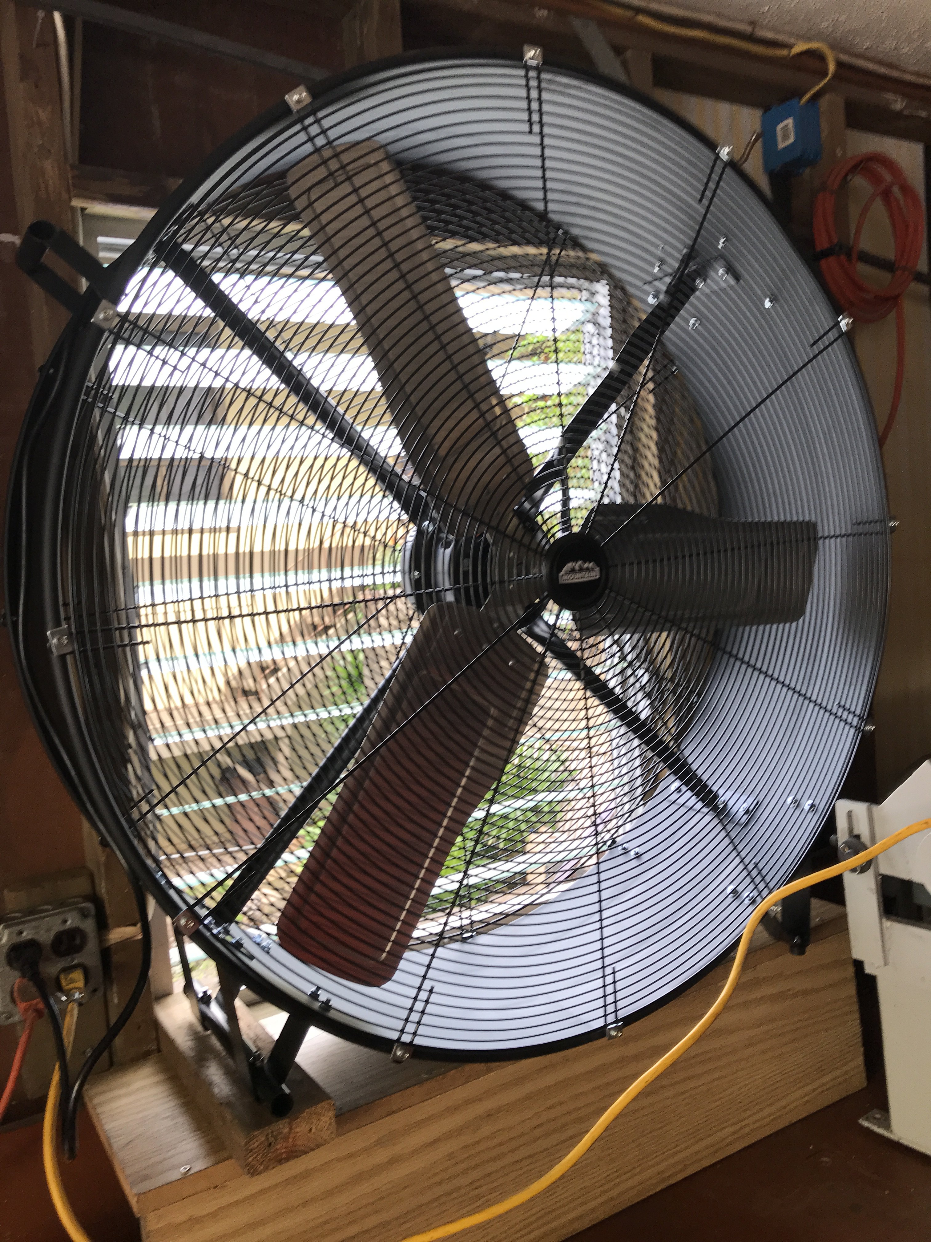
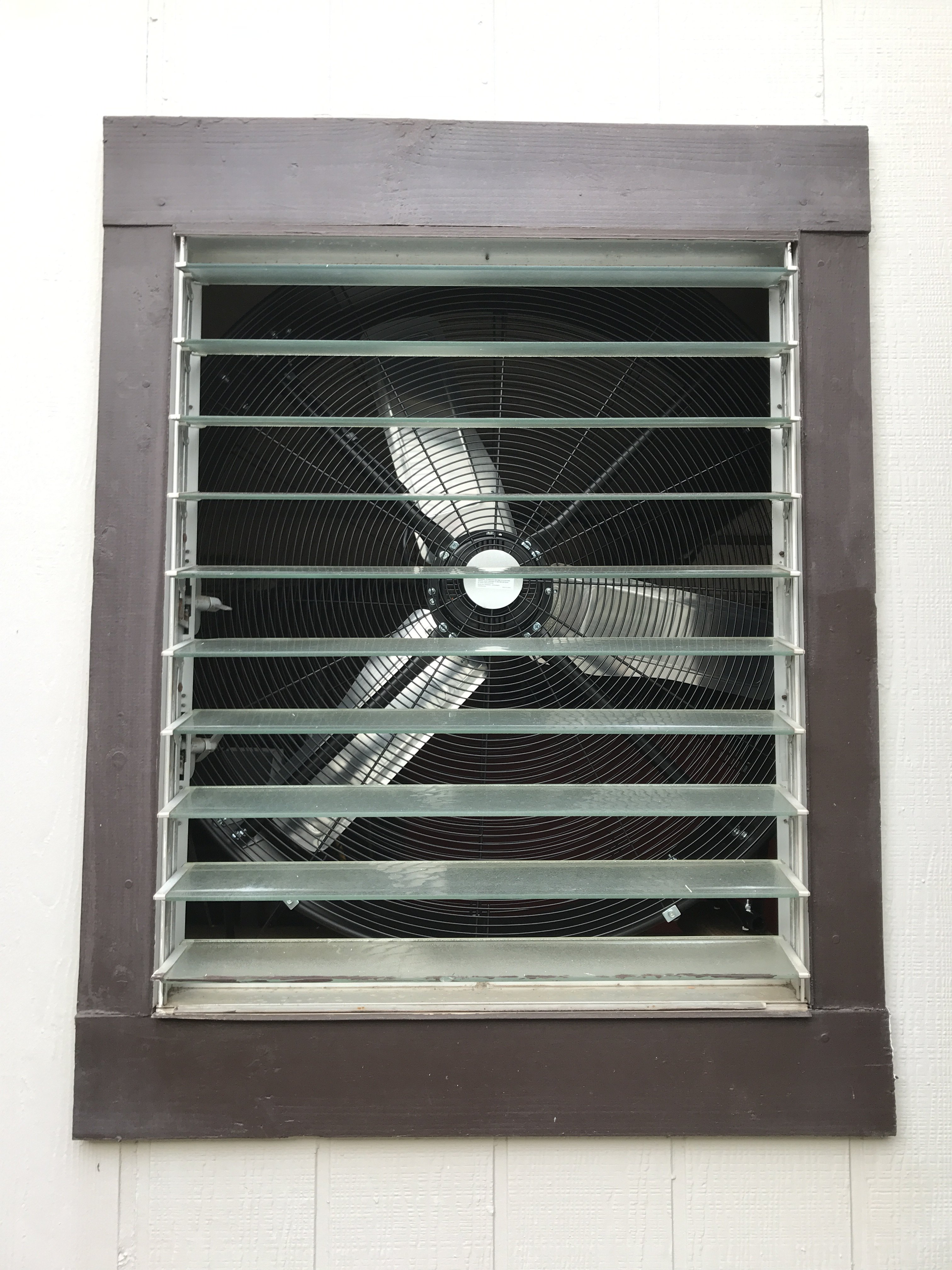 Outside view of fan with louvers open
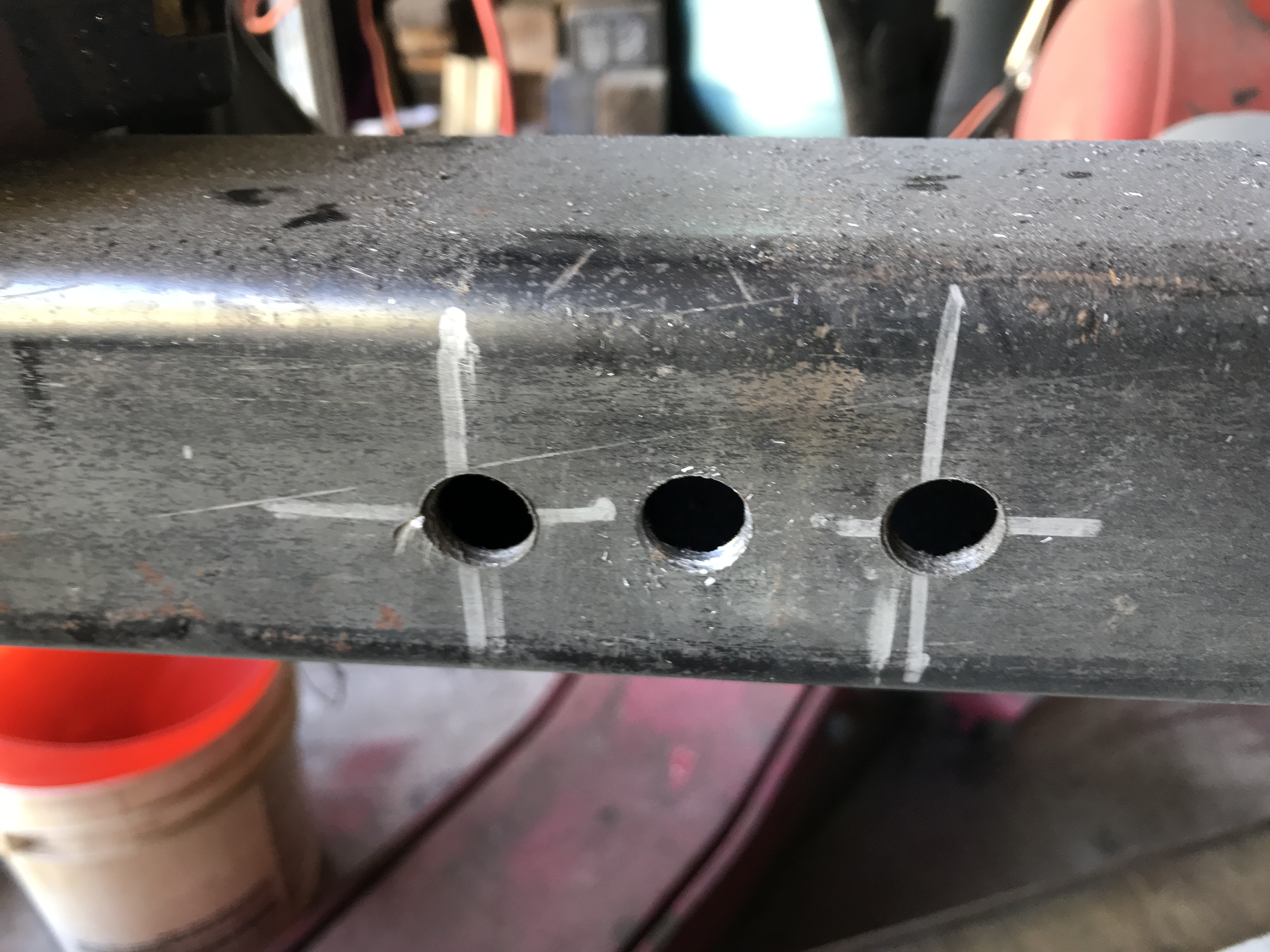 Stabilizer mounting hol
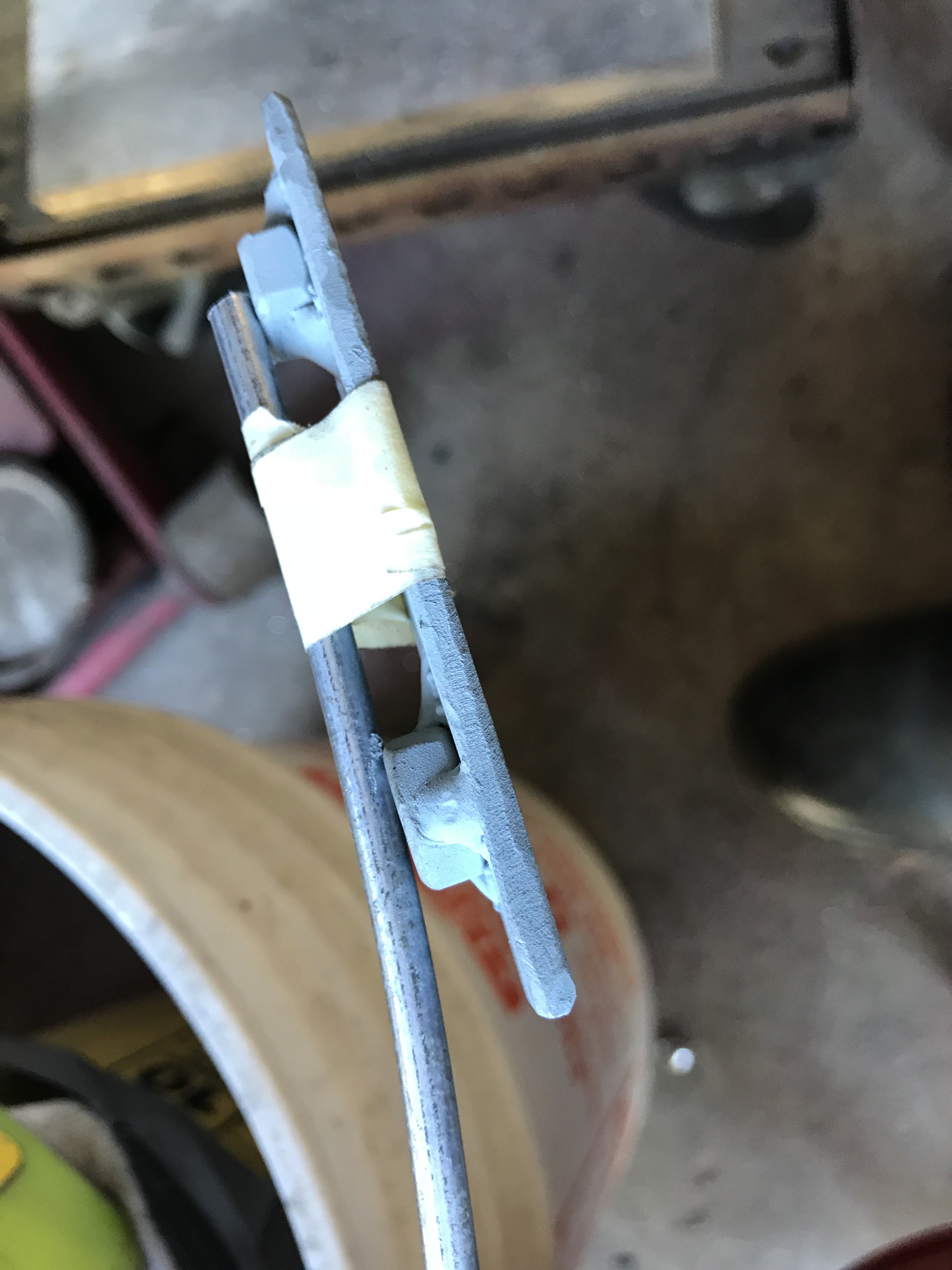 Two 8mmx 1.25 nuts welded to 1/8 x 6" steel plate


 As if the Holidays wasn't keeping me busy already, I had a plumbing leak in the house to repair.
 Then it was covered by self etching primer to prevent corrosion.
 The car was p[aced on its side to remove rear undercoating
 Then the area was media blasted with Number #60 grit abrasive. This media is one step rougher to remove heavy underseal in tight areas
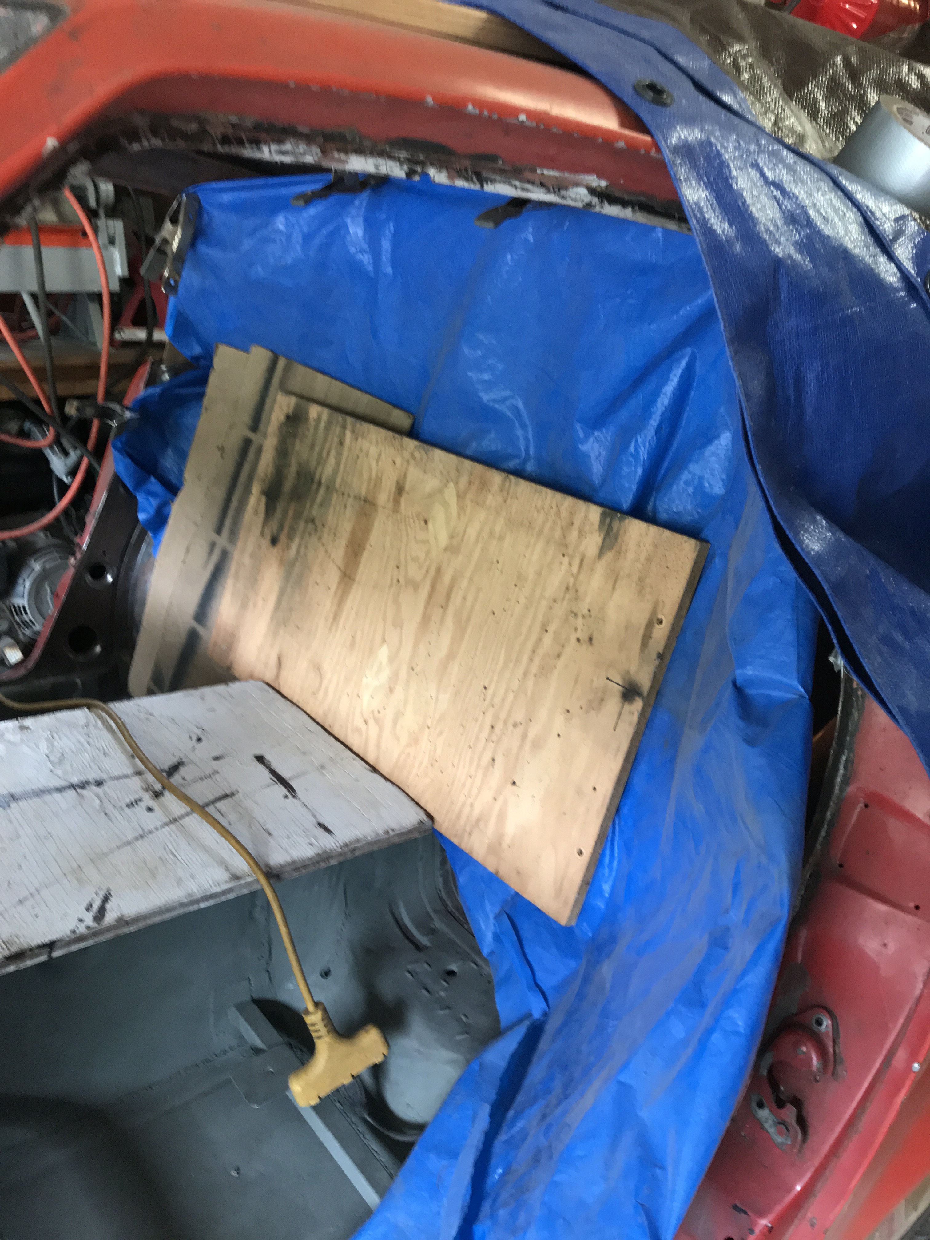
 Put a large plywood to hold up the blue tarp covering the open hatch area.
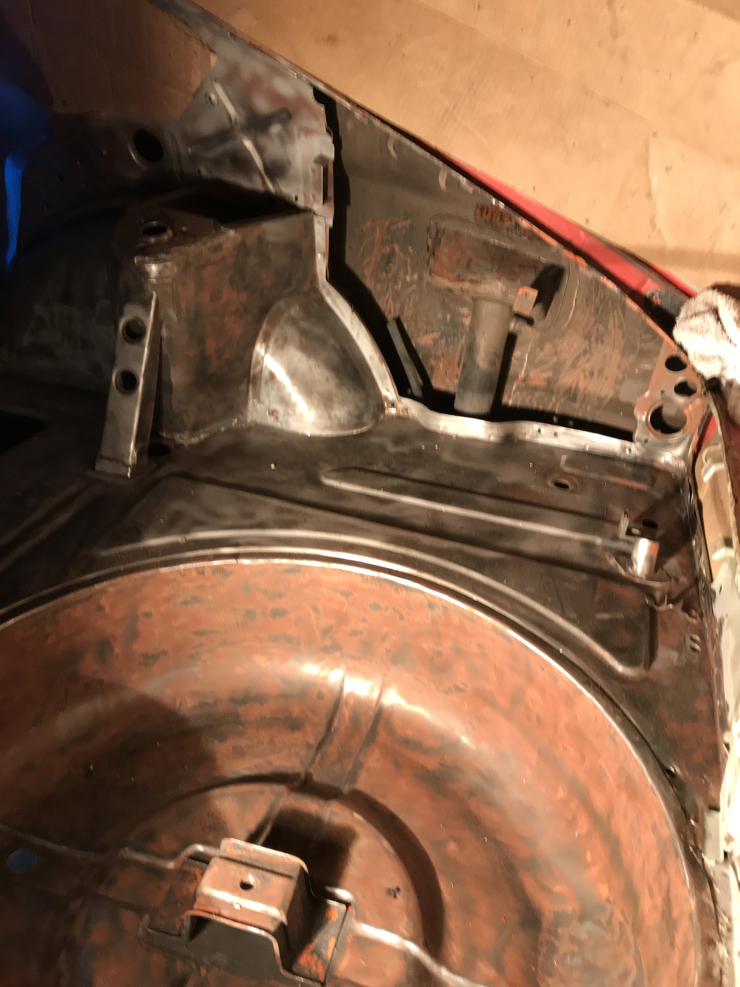 Richard, the spare tire area was cleaned. Saved for now.
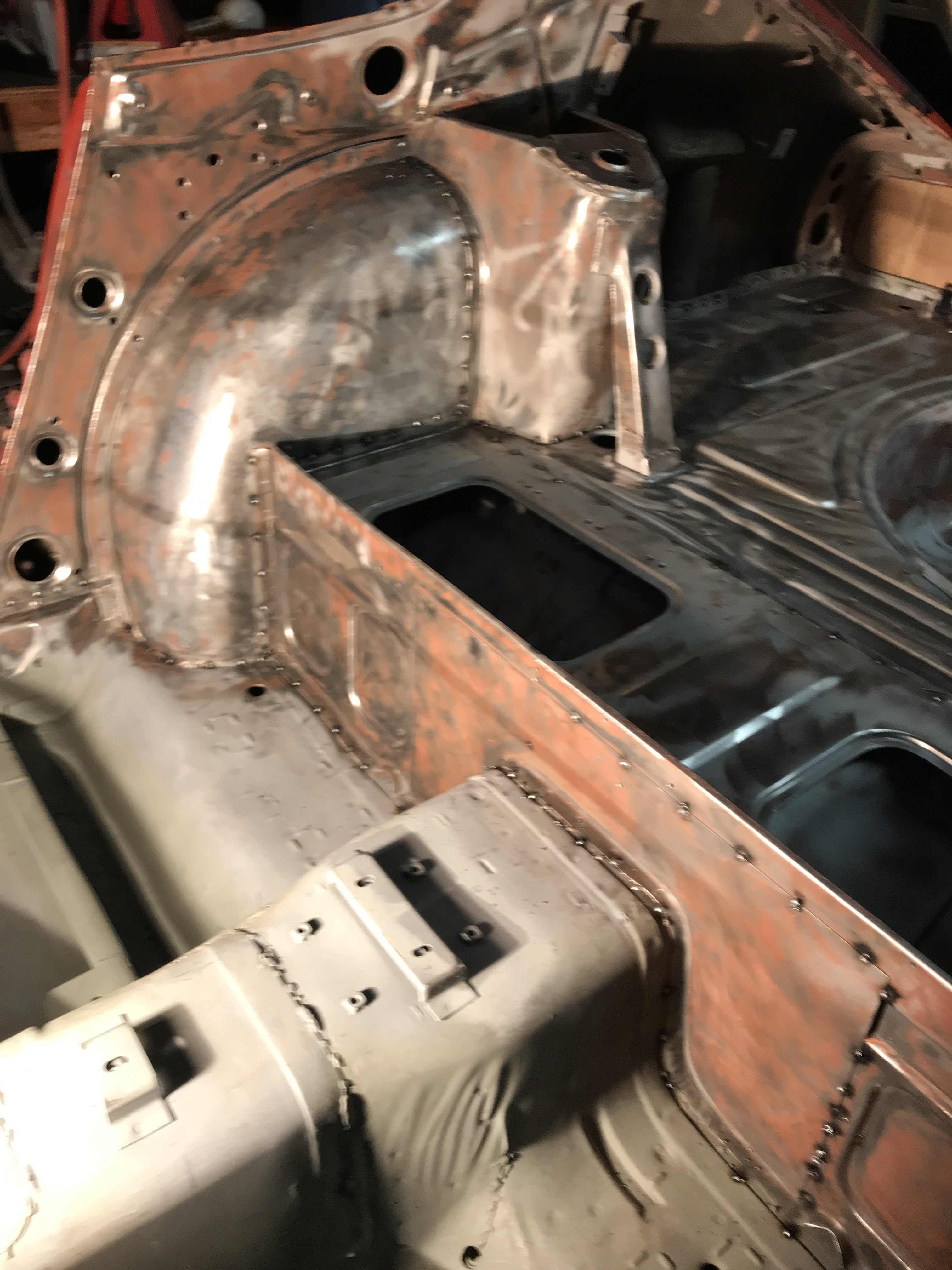


 passenger's mounts
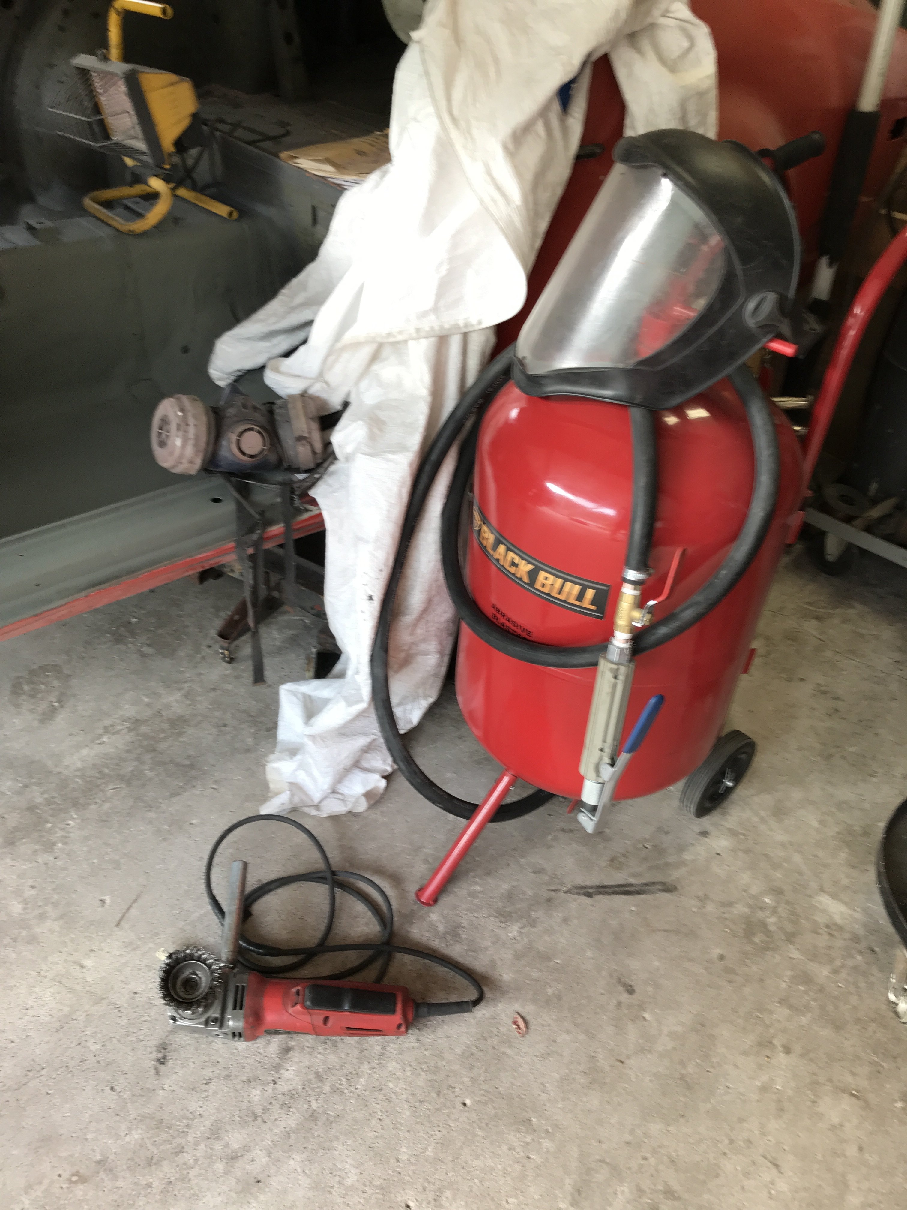 Tools used for undercoat and paint removal
 Strut tower also welded,
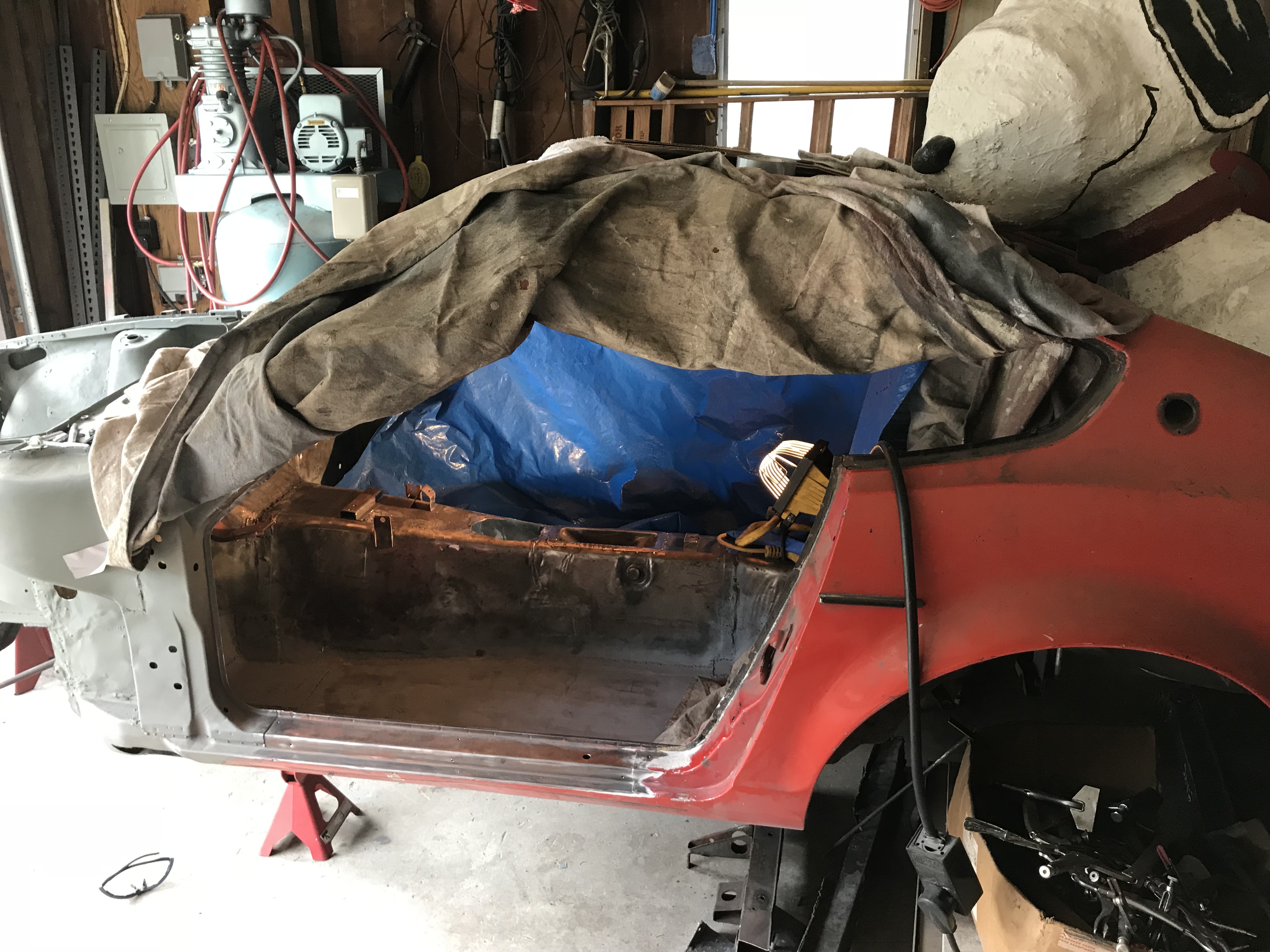

 This Chevrolet High Performance manual has all necessary part numbers to
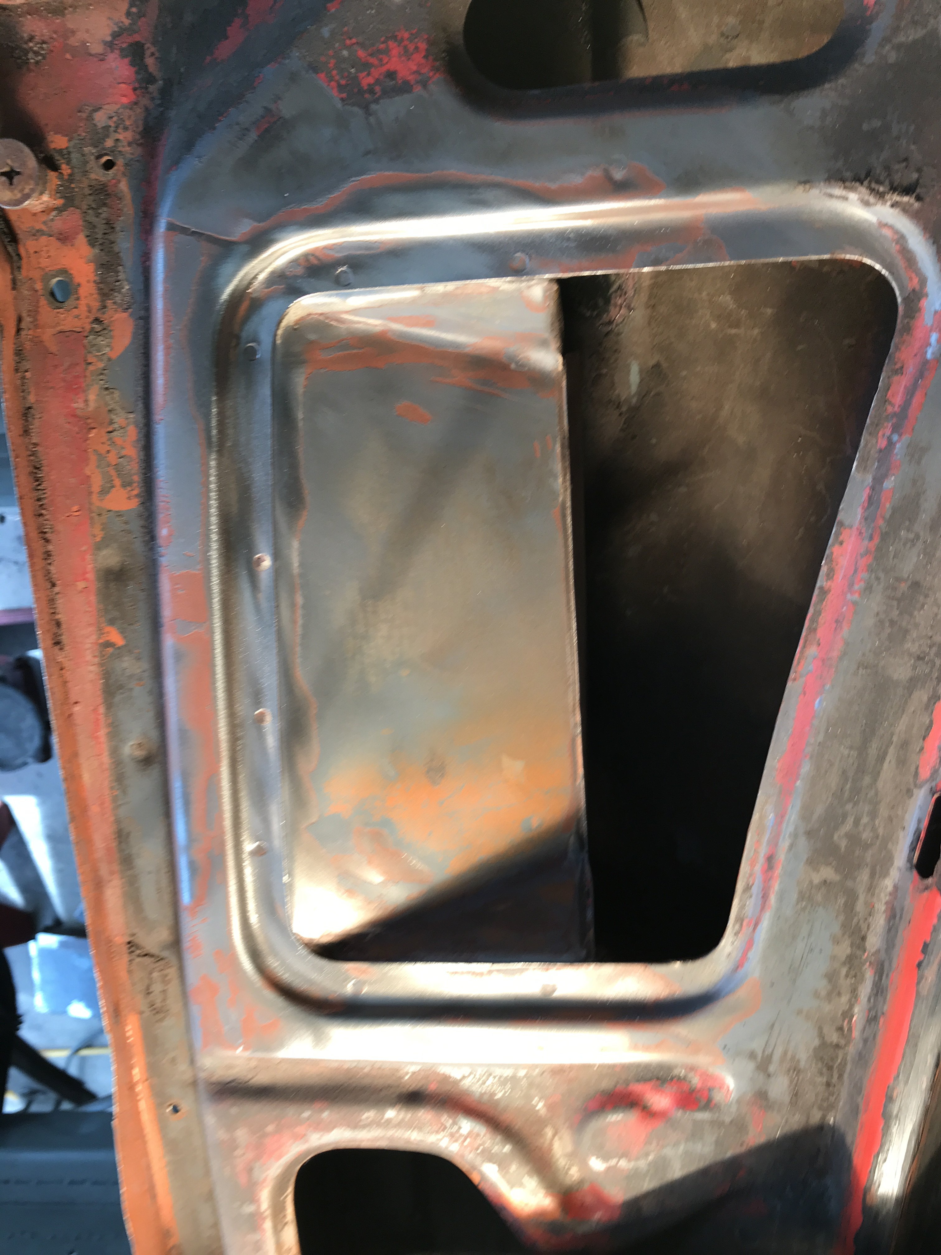 wire brushed the cowl area but vent must be removed to
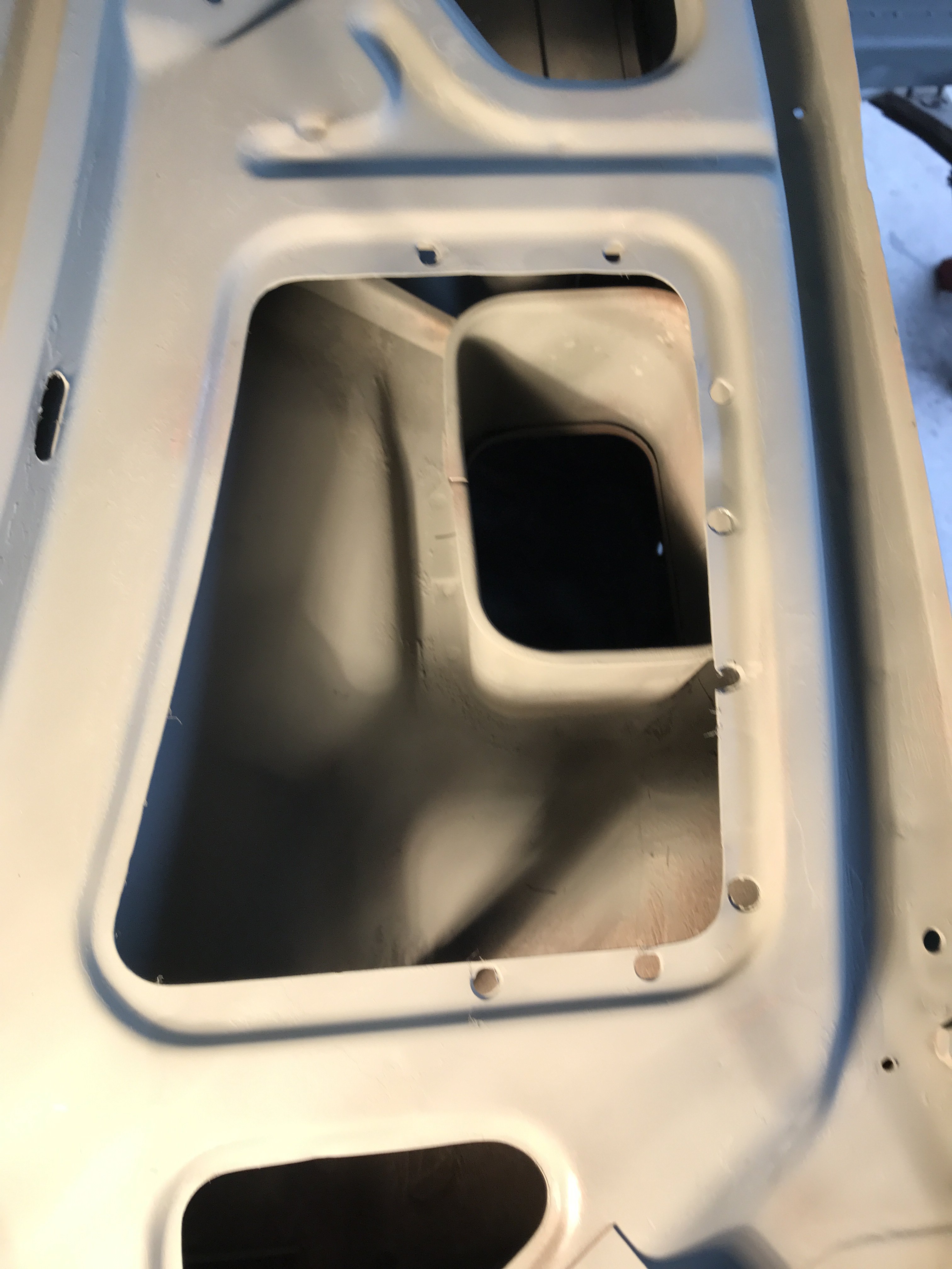 After cleaning , area was primed with self-etching primer to prevent rust before media blasting.
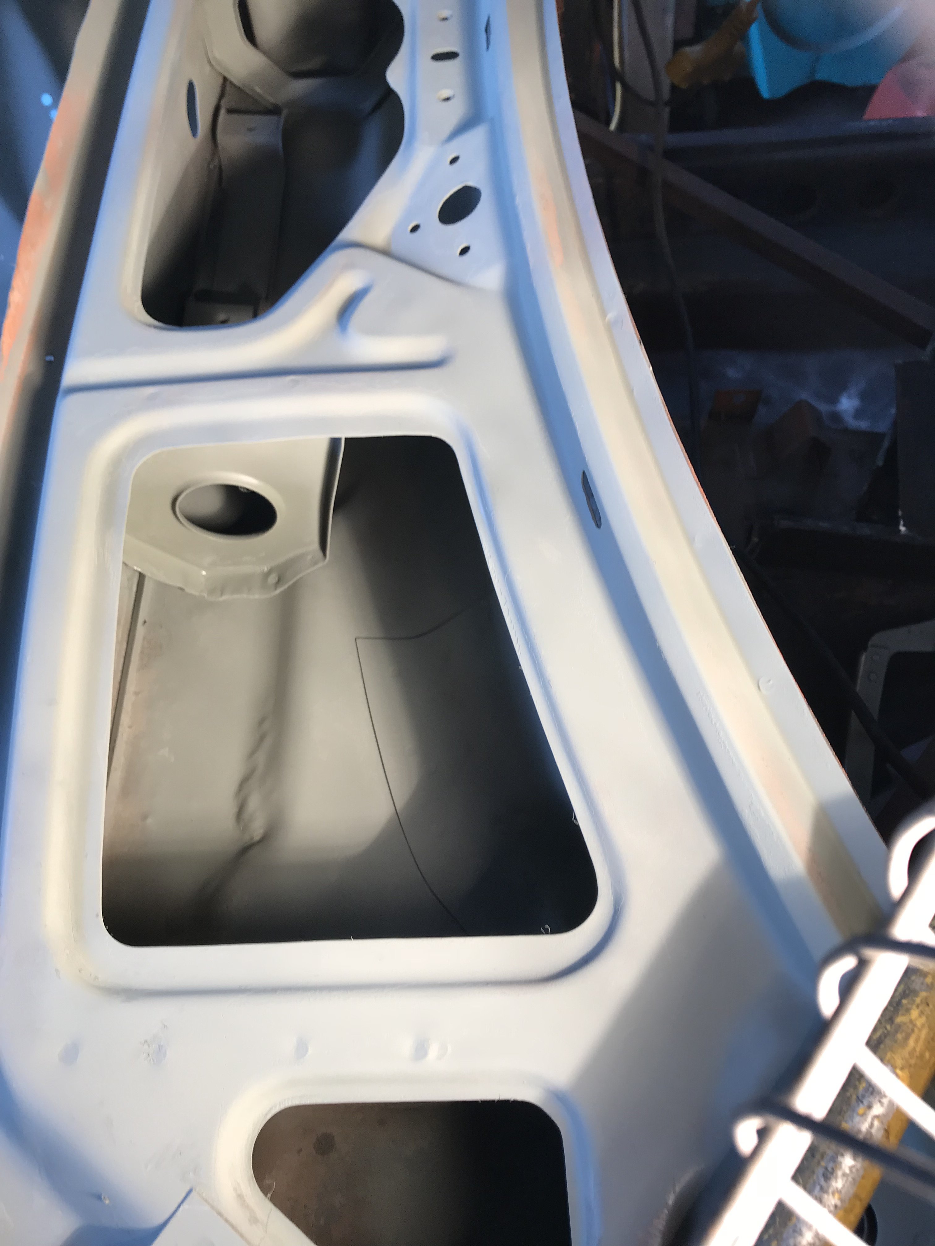 Driver side cowl after priming.

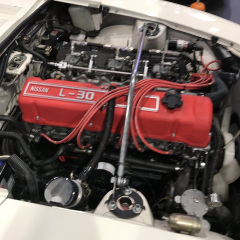 Bored out motor with Weber carbs
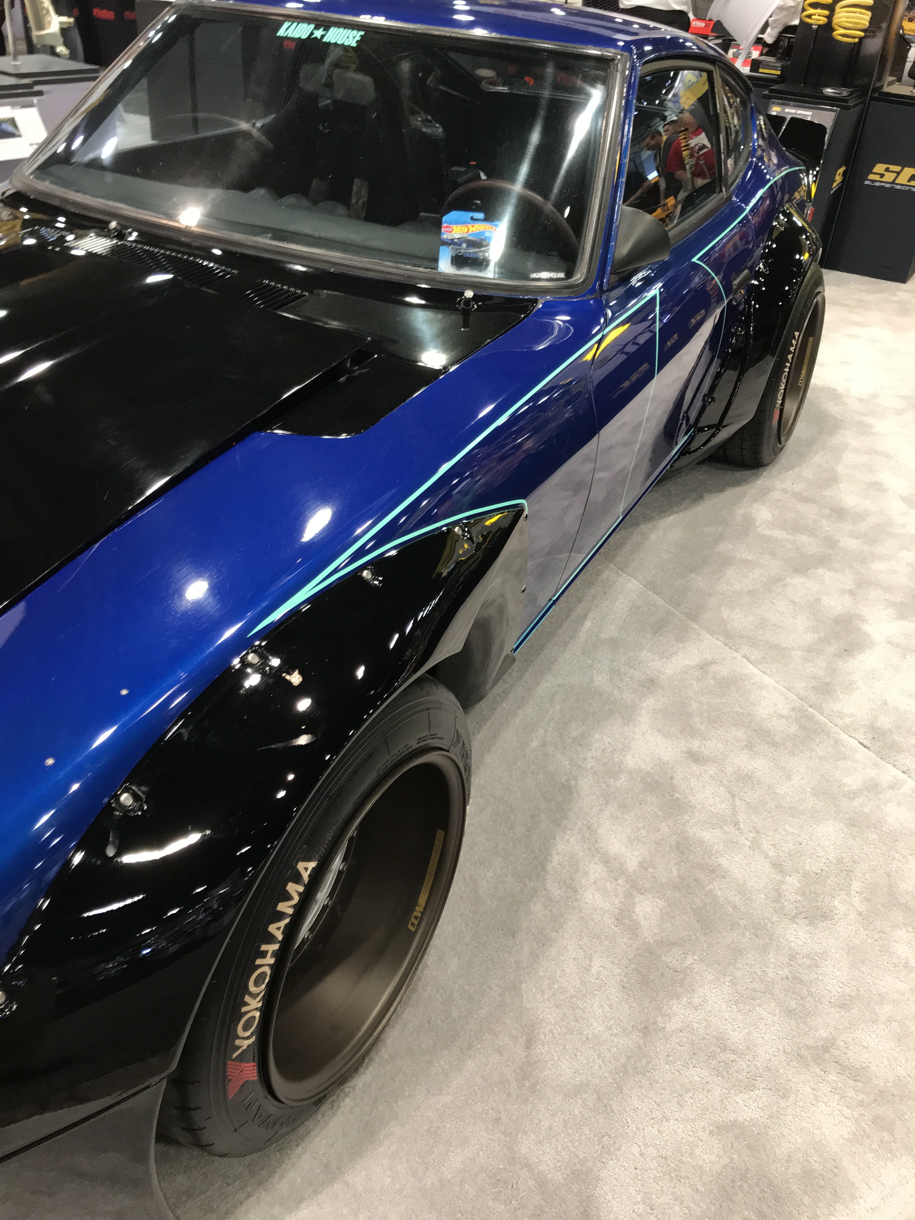
 Wide flared 240Z car. Someone told me that there was a early Z with a Skyline twin cam motor but I must have missed it. There were hundreds of cars and trucks to see at the show.

 Patch had to be held in place with Cleco clips for welding. Sheet metal screws were also used.

Richard Oben LS1 series 1 240Z build
in Gen III & IV Chevy V8Z Tech Board
Posted · Edited by toolman
correcting text/pic
Richard, Thanks for the Rapid Answer. Before I heard about some guys using Ford 8.8, I was thinking about putting in the whole rear suspension
from a late model Camaro and basically narrow it to fit. That way you get a beefier wheel hub( although 5 lug). Also, it would limit machine work to
shortening both axles. Most of late model cars use an independent rear with four bolt mounting system so it could be possible. I was looking for
a wrecked Camaro so I could take measurements to even see if this swap was possible. But I got diverted to the paint booth build and still got more
rust work to do. Anyway, somebody might already done the swap already.
Toolman
factory Camaro IRS suspension