

toolman
-
Posts
519 -
Joined
-
Last visited
-
Days Won
7
Content Type
Profiles
Forums
Blogs
Events
Gallery
Downloads
Store
Posts posted by toolman
-
-
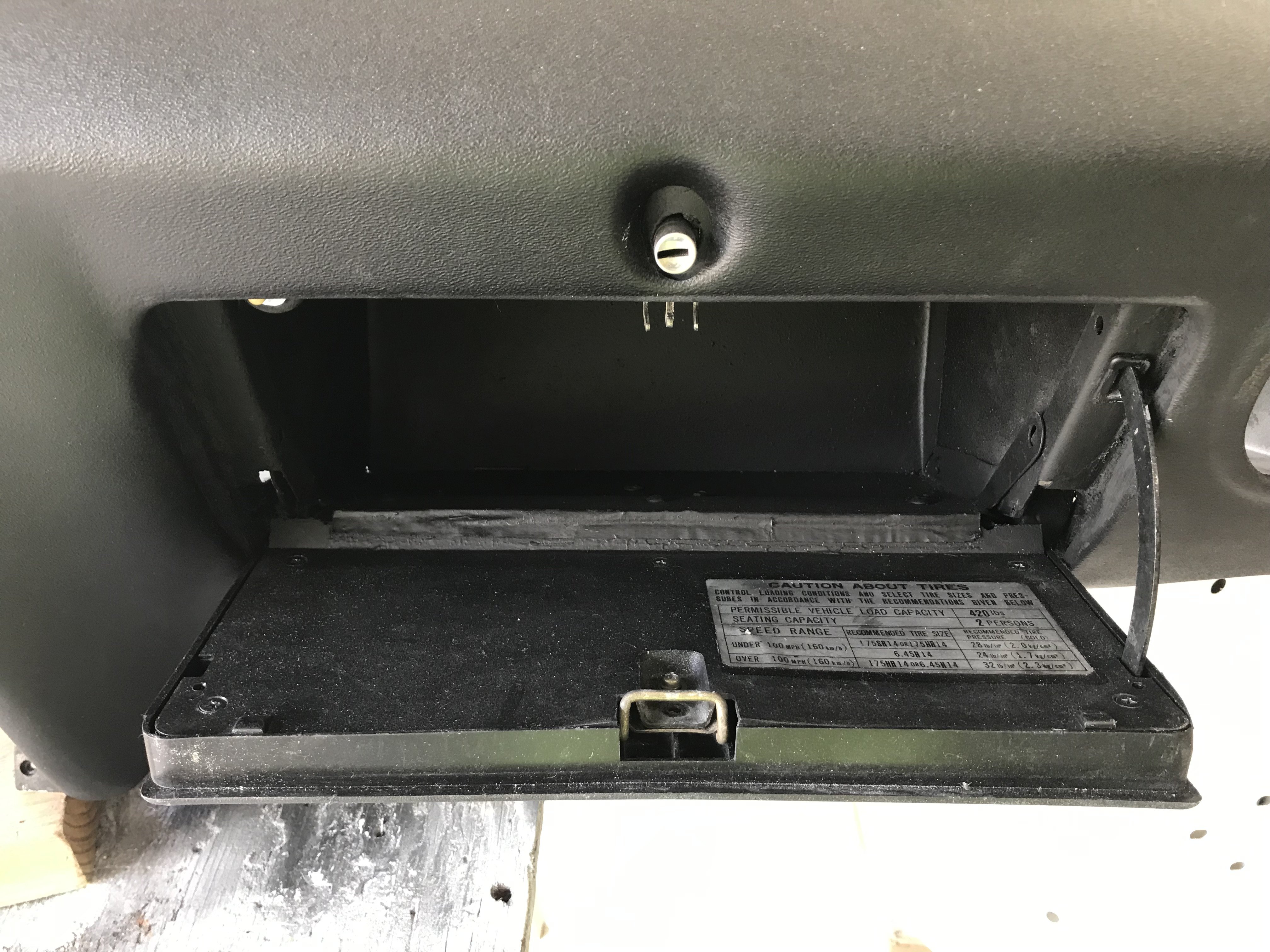
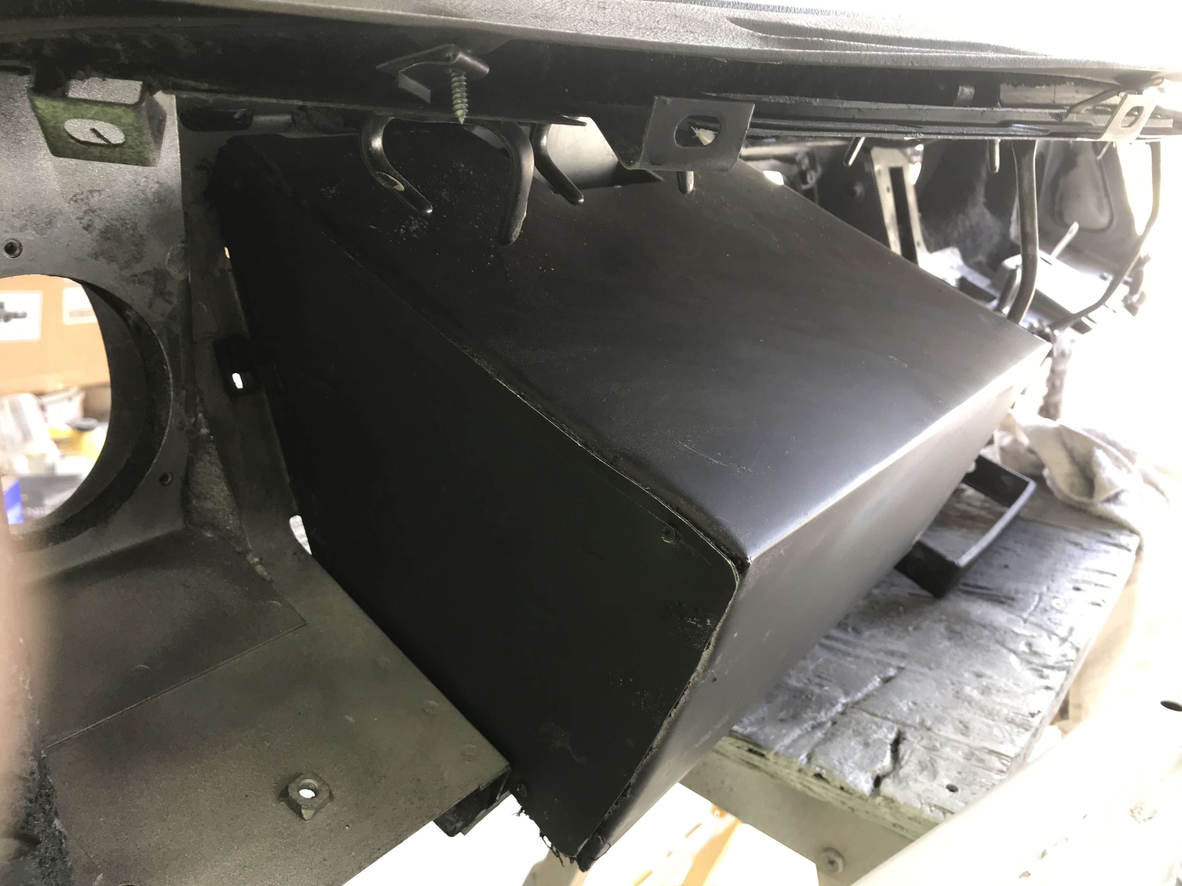
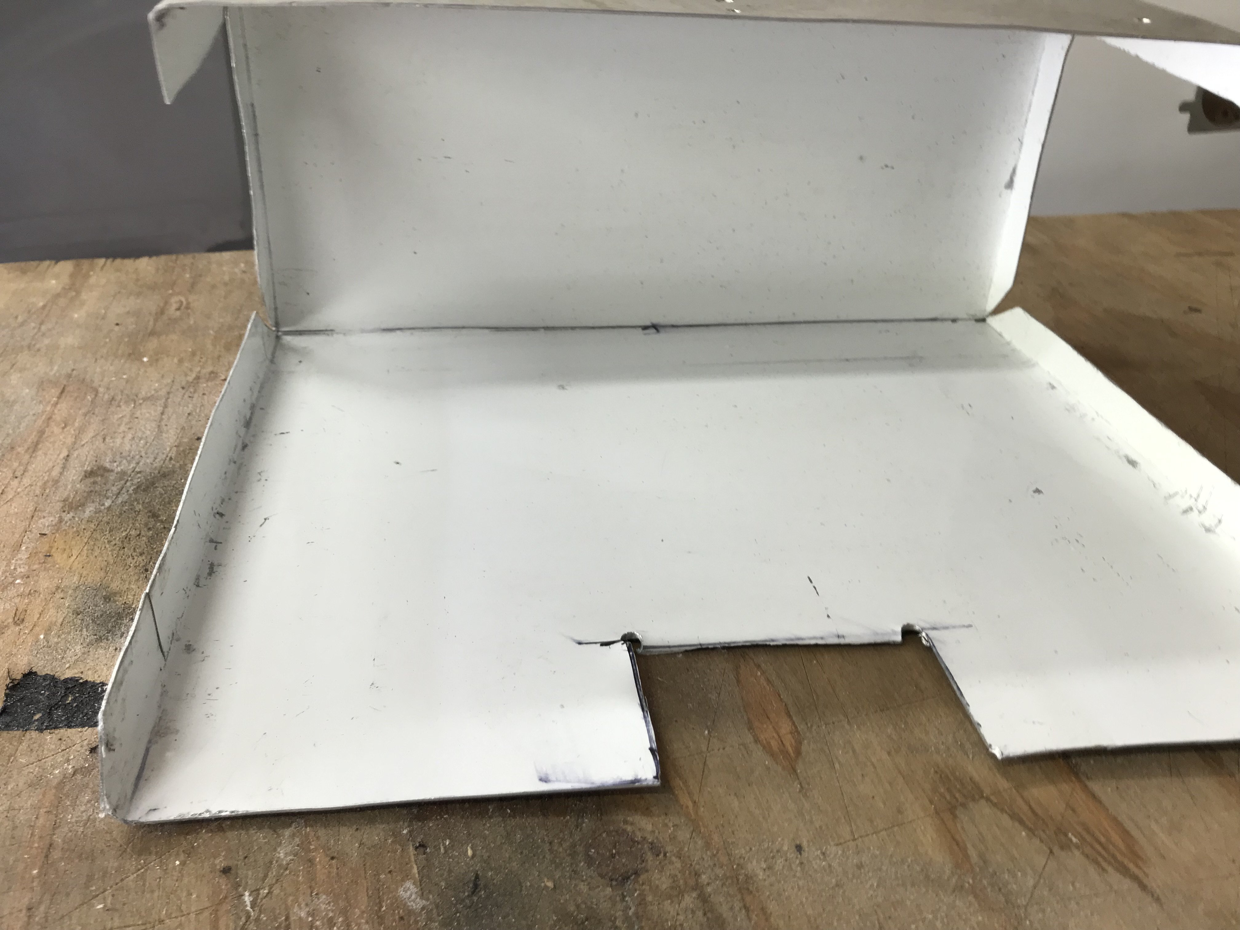
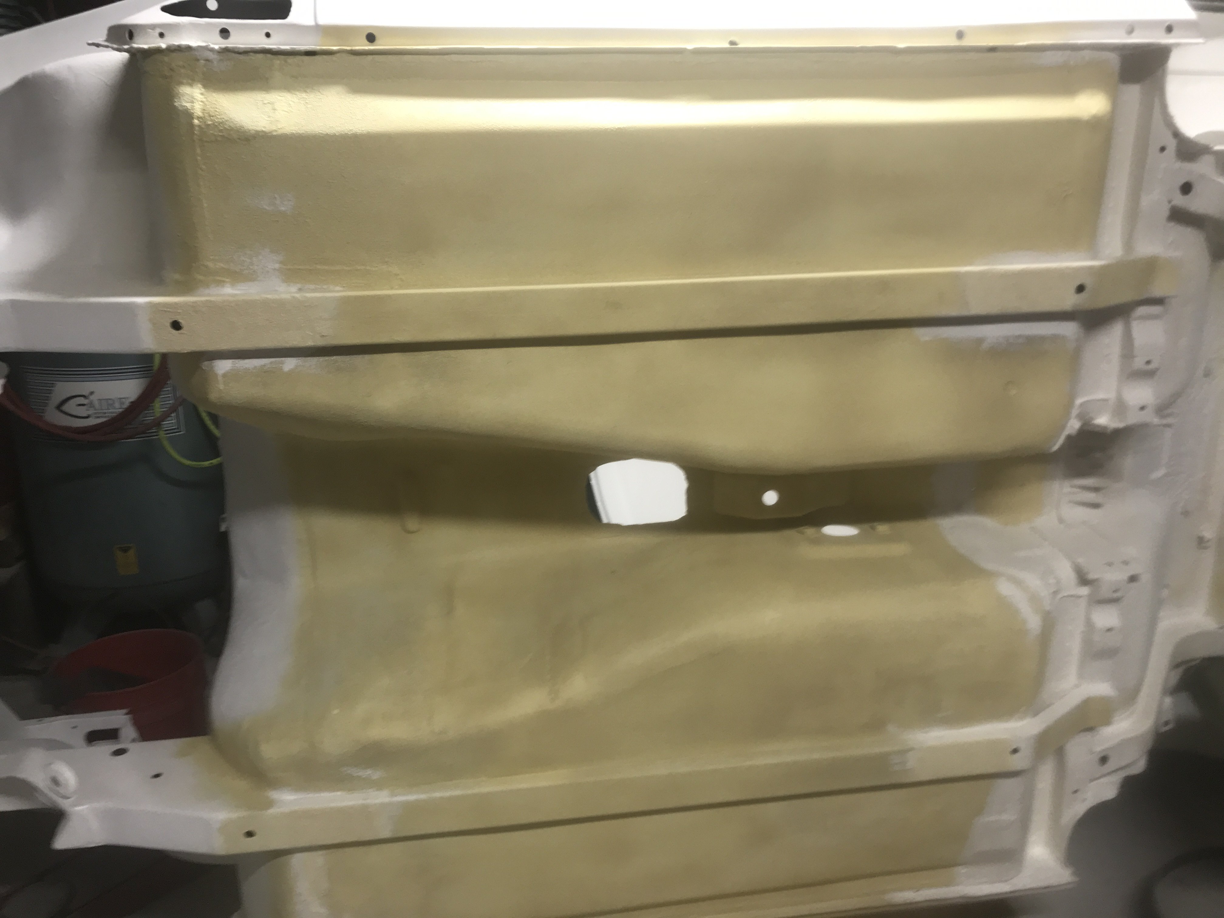
Finished the replacement aluminum glove compartment box.

Rear side of box
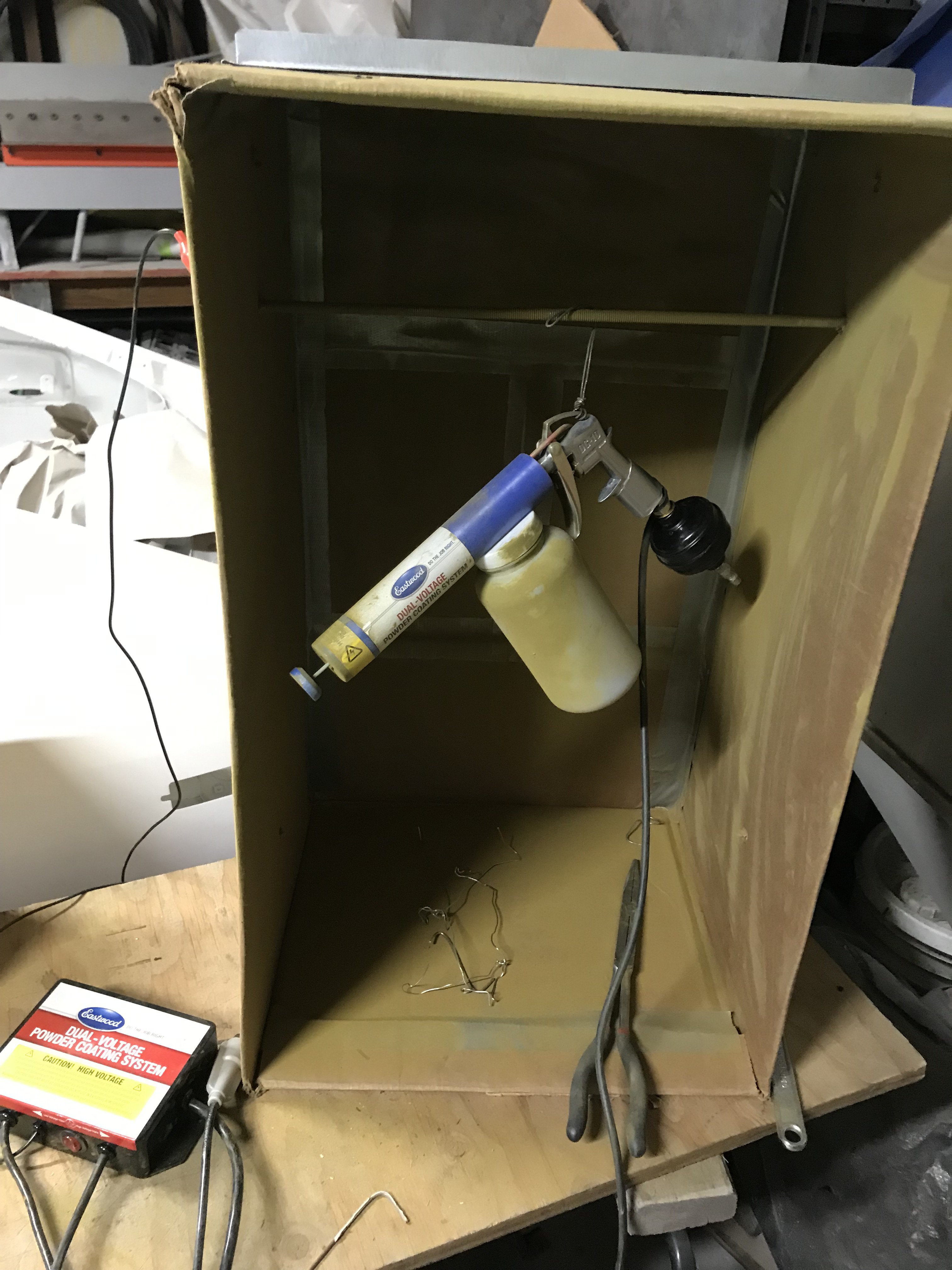
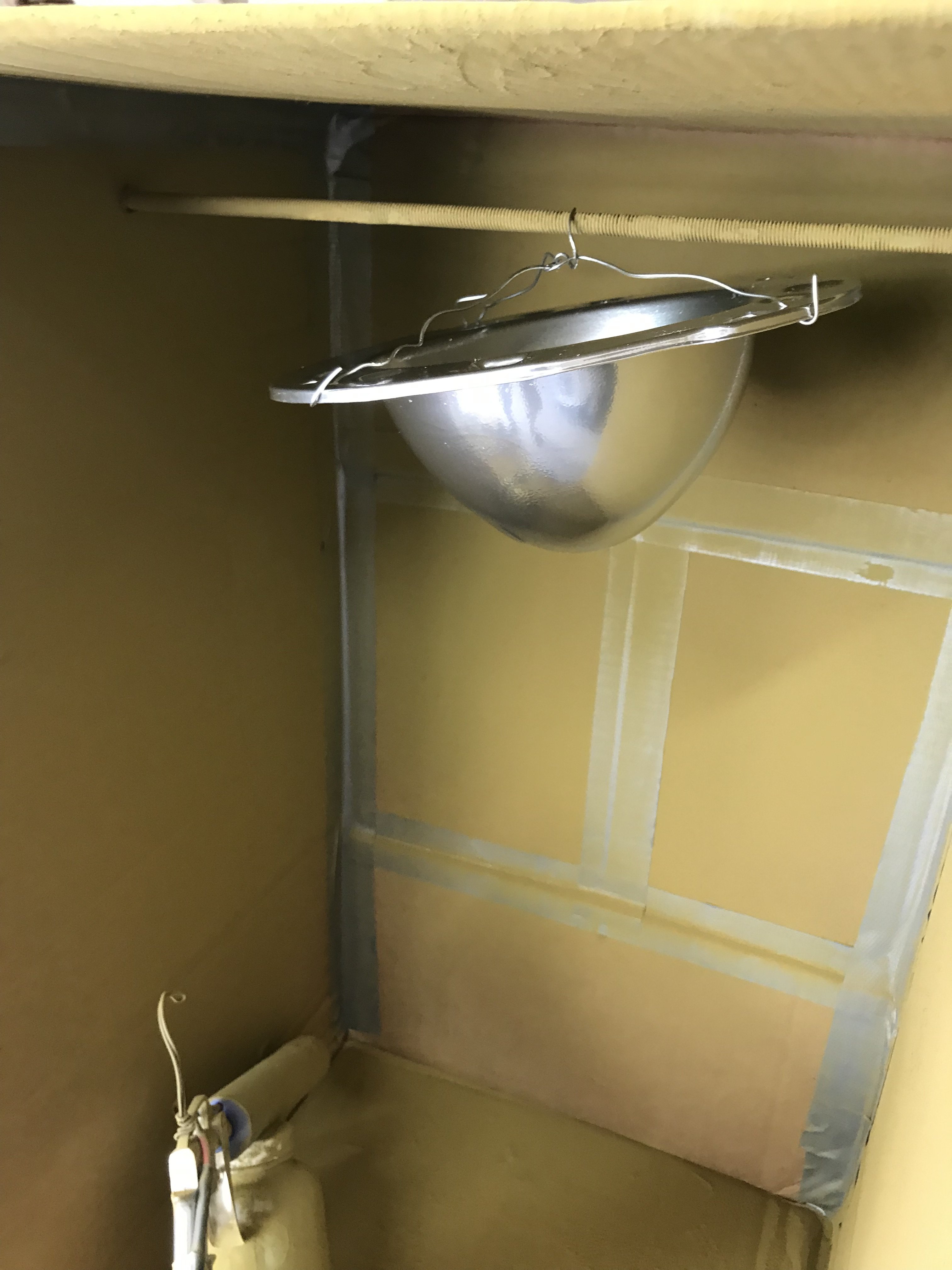
Now I went to something that I always wanted to do--Powder Coating. So I ordered a Eastwood Powder Coating kit for $100. A cardboard box was
used for the powder spraying booth. Note there is metal rod in the box to hold parts to be coated and act as the grounding for the unit.
The system is low maintenance. Just blow air to clean the gun and bottle. The booth can be
vacuumed after every color coating. Spraying the powder has a low learning curve.
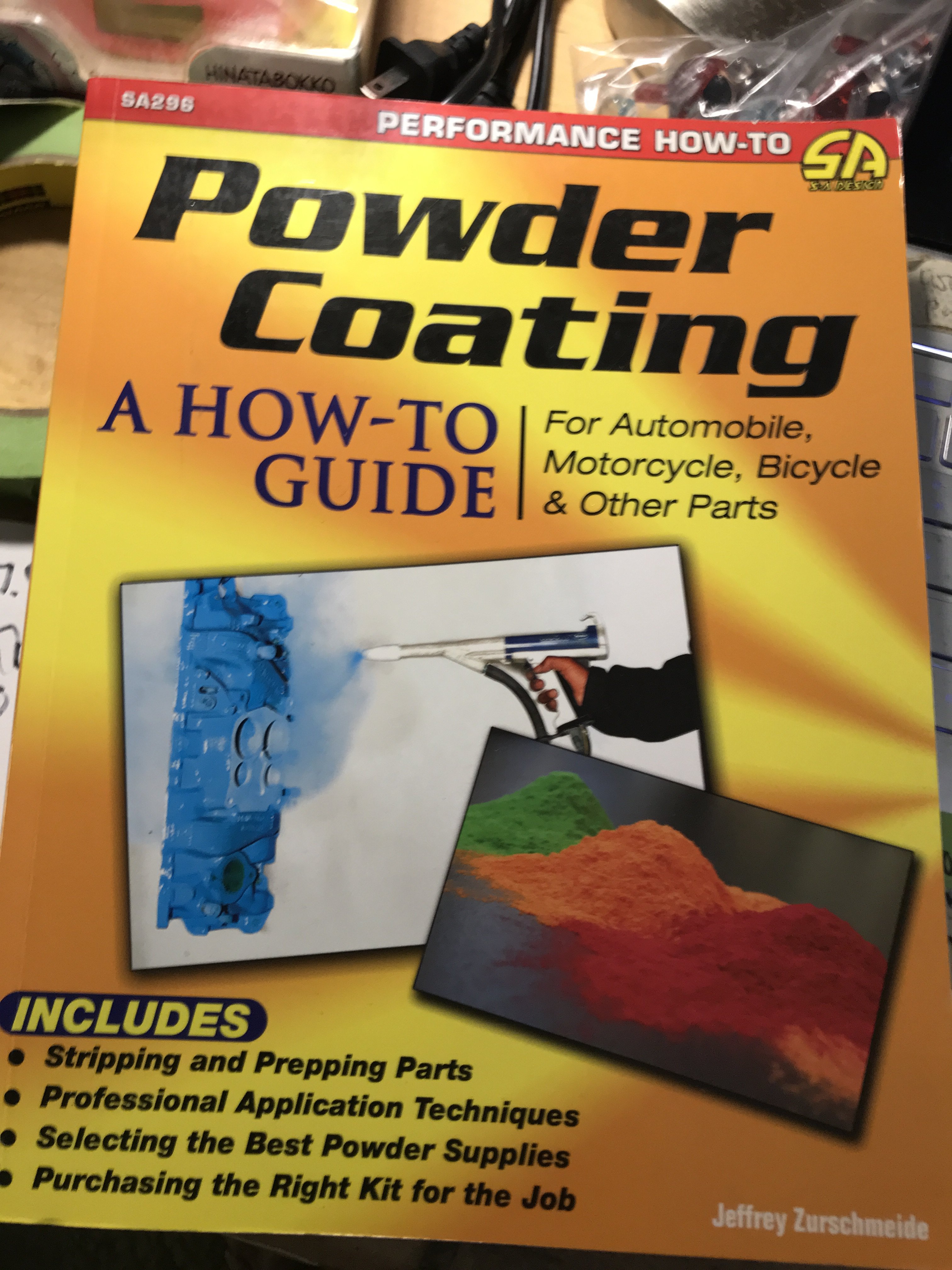
I would recommend this book before actual powder coating as it has many helpful tips.
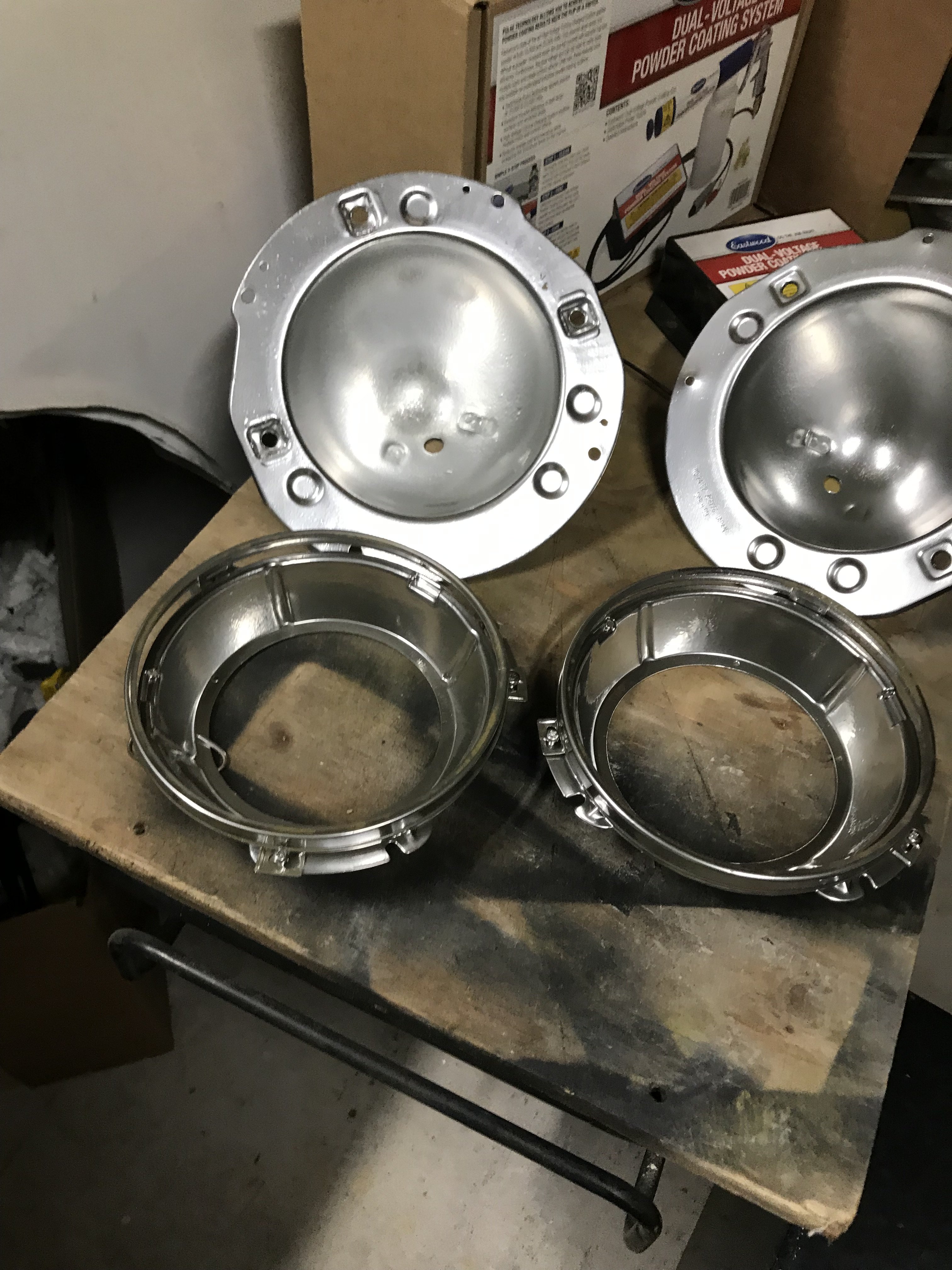
Pic of the before and after powder coating of the head light buckets.
Note-the plastic headlight adjusting screw inserts must be
removed otherwise the oven will melt them.
The headlight bucket in my Toaster Oven for 20 minutes at 400 degrees.
After baking, the bucket was moved back to the spray booth to cool off.
Note-The is only the Base Coating and must be followed with a Top Coat to provide the right color.
Pic of the headlight assemblies after Base Coating.
Picture of hood hinge before spray blasting and powder coating.
Hood hinges after Base Powder Coating.
Note- The original hinge were zinc plated then yellow chromate dipped. Chromate is a very toxic chemical and hard to
dispose of. The exact color will be impossible to duplicate with powder coating because it does not allow mixing of powders.
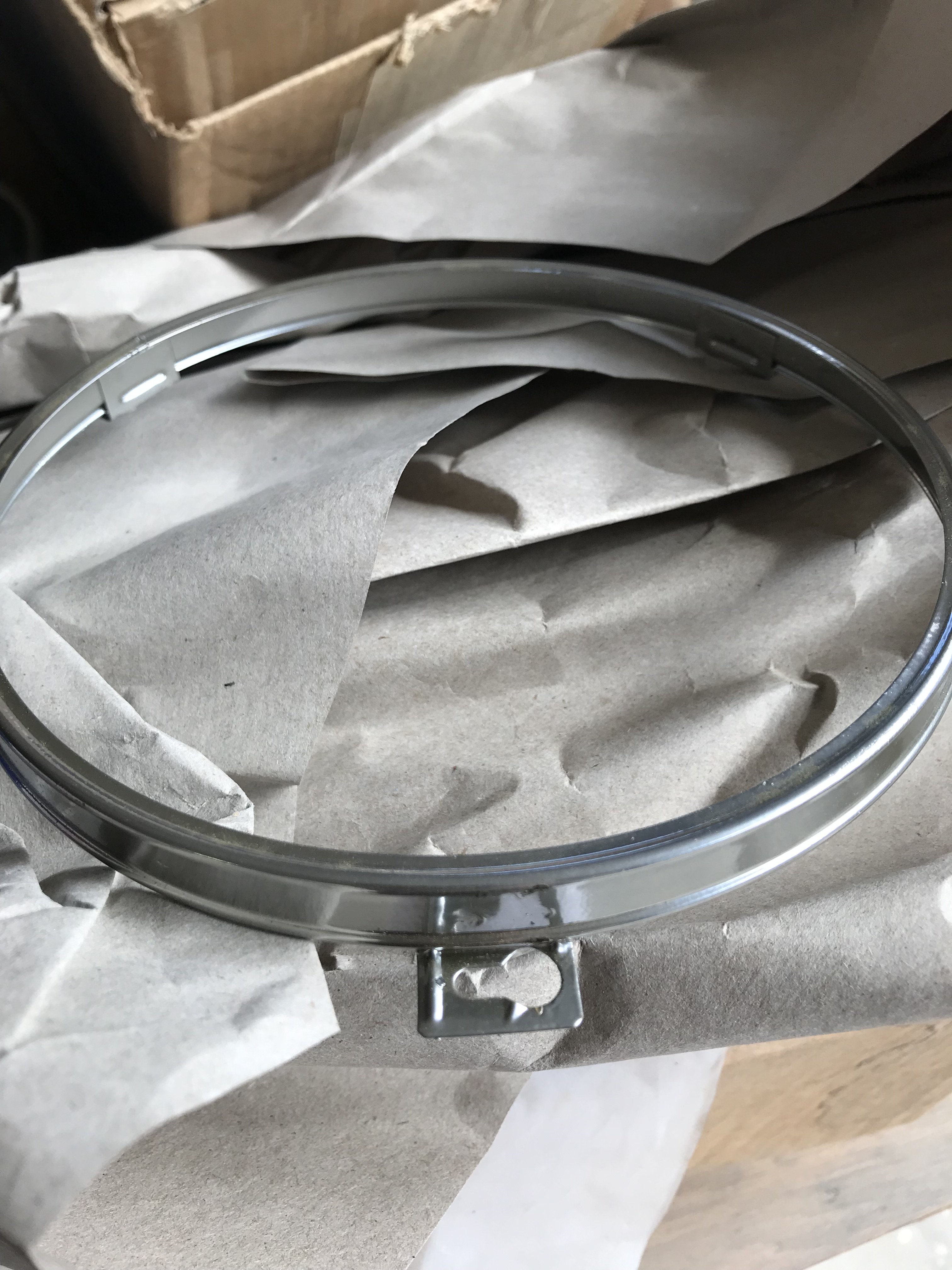
However, powder coating of the headlight retaining rings closely resembles chrome plating.
Now. I have to wait till the TOP COAT Powders to arrive from the Mainland so I can try to match the Chromate process. Wish me Luck!
-
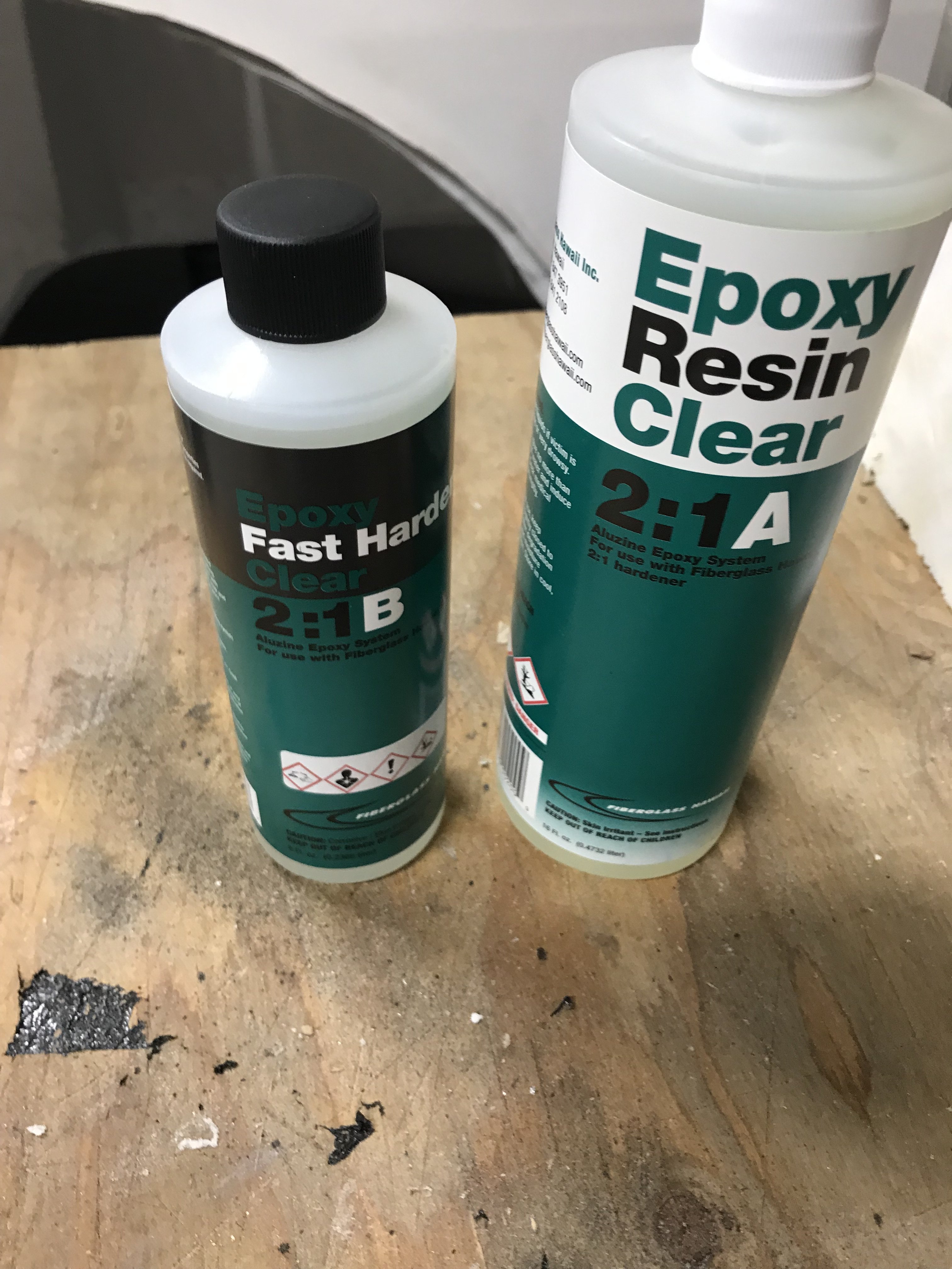
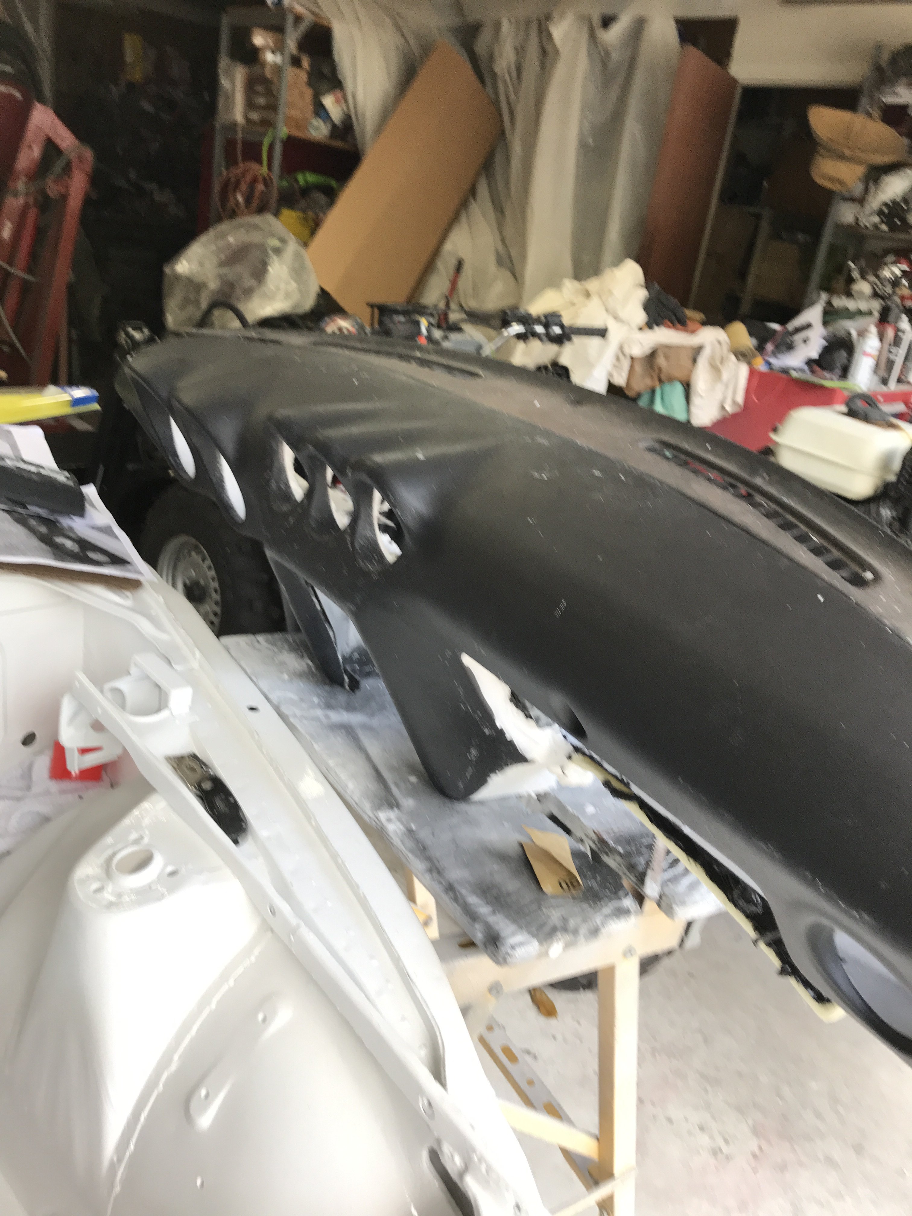
I was going to use Fiberglass Resin over the foam but decided to use Epoxy Resin instead. The reason being fiberglass resin would not adhere the dash plastic material.
Also, Epoxy Resin is much stronger than Fiberglass resin
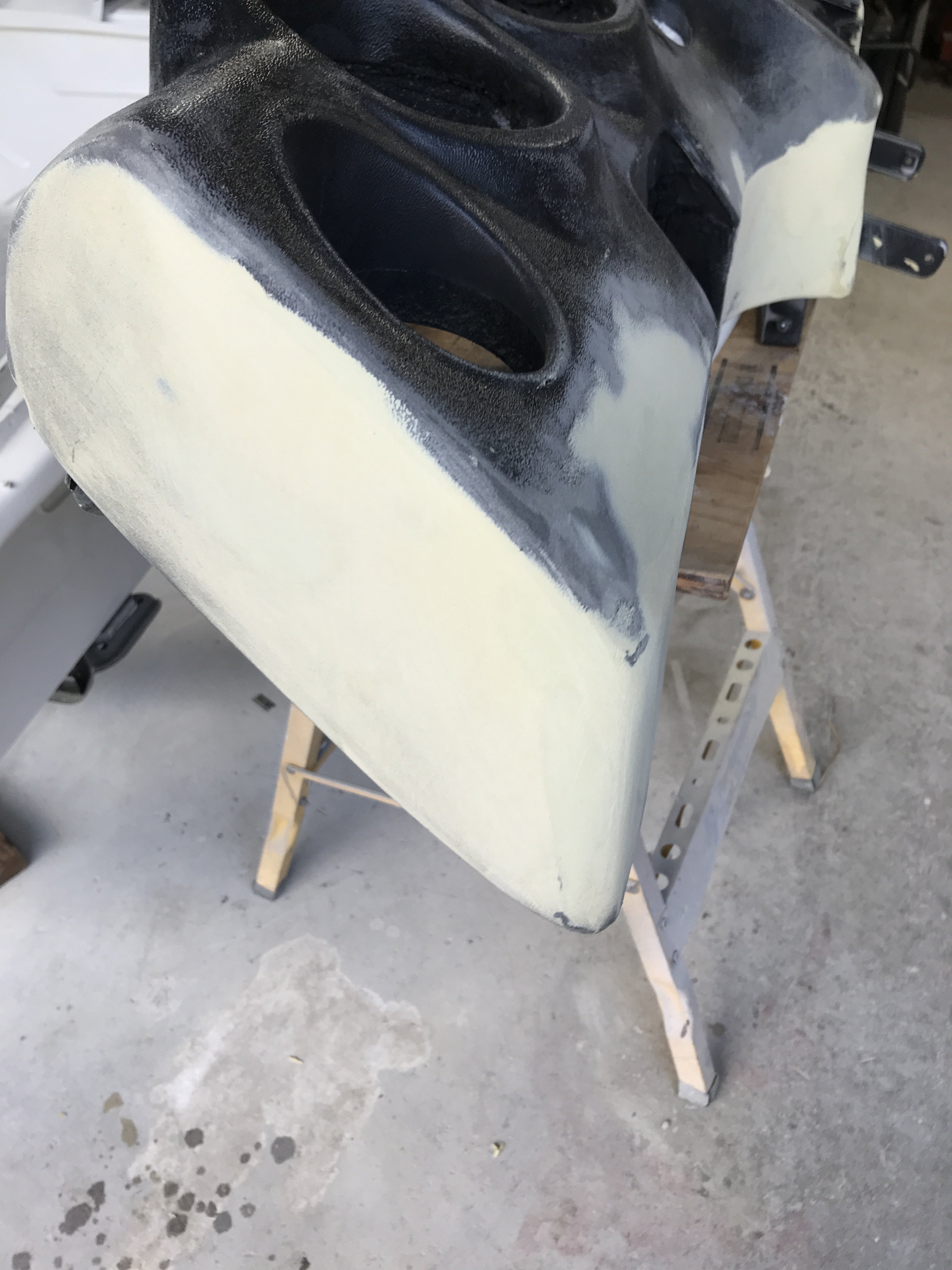
View of Left side of dash with Epoxy Resin applied on foam.
Same section after Body Filler finish sanded.
Bottom view of dash after finish filler sanding.
Note-Blending areas between replacement foam section and original dash are smooth.
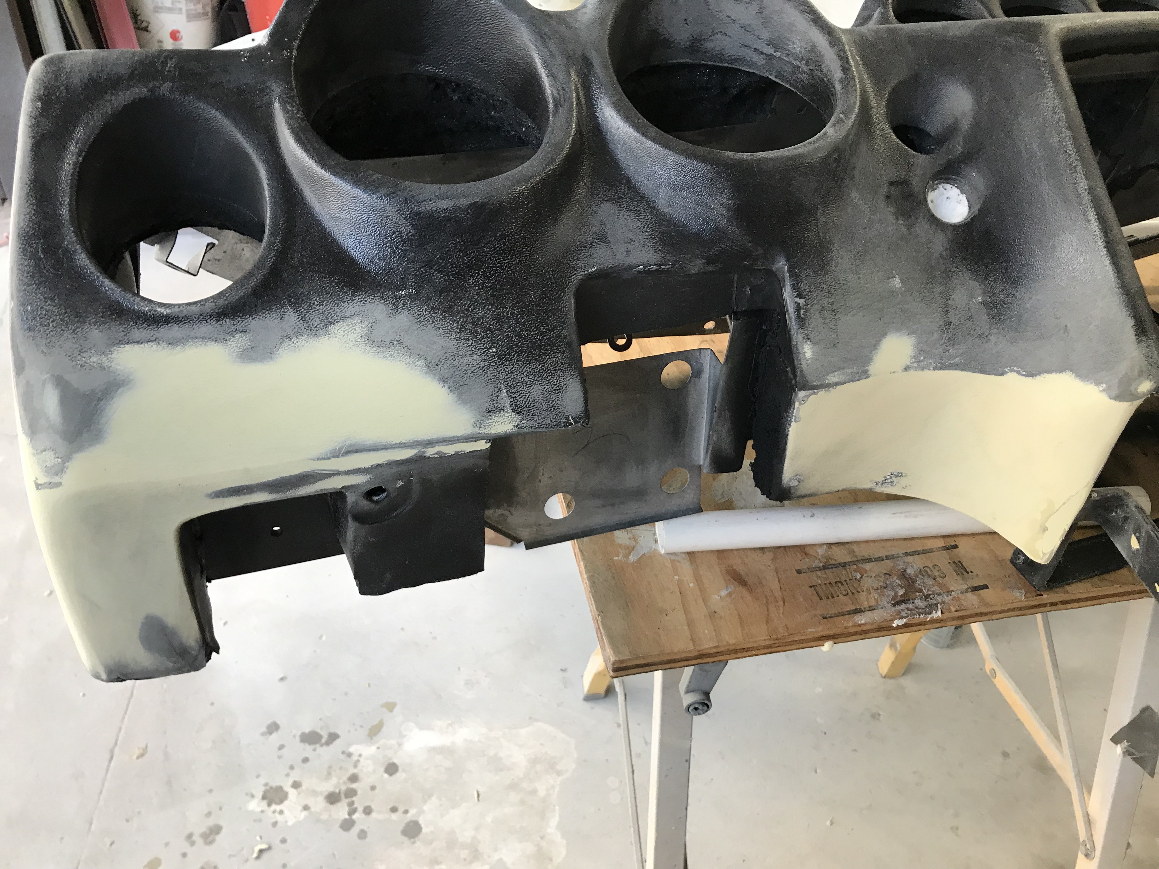
Center view of dash bottom after finish filler sanding.
Bottom view of Right side of dash.
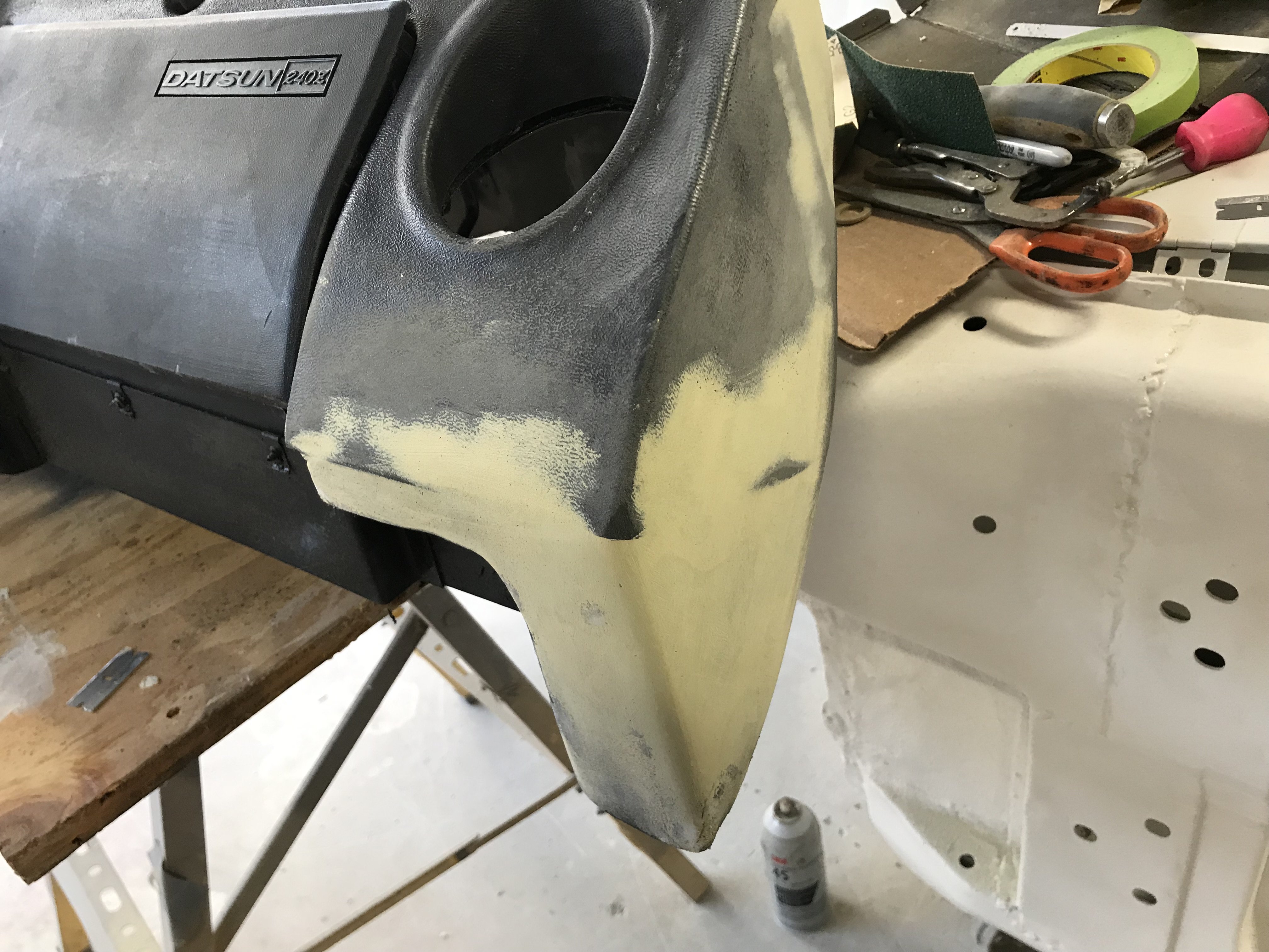
All of the repaired areas were next epoxy primed.
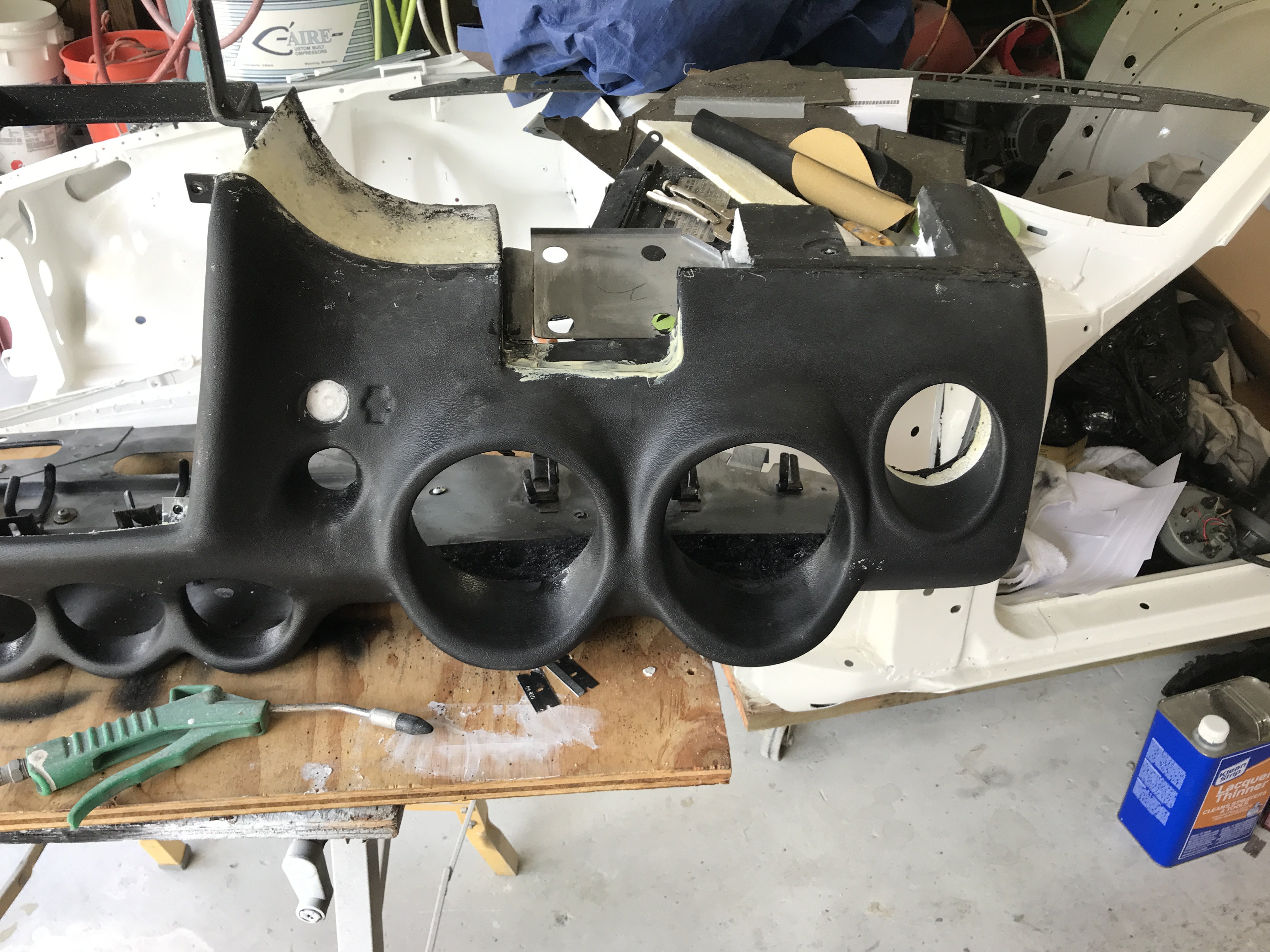
Black Trim/Bumper paint and Sem Products Texture Coatings were both used to finish paint the dash.
The entire dashboard were painted with the Black Trim paint to create a even color base.
Then the Texture Coating was utilized to create a textured surface for the repaired areas. This texture can be controlled by adjusting spraying distance and speed of
spraying.
After allowing the paint to cure overnight. I sanded the whole dash with 3M Fine Grit Gray Fiber pads, The texture is also controlled by the amount of material sanded off to
match the original texture as possible.
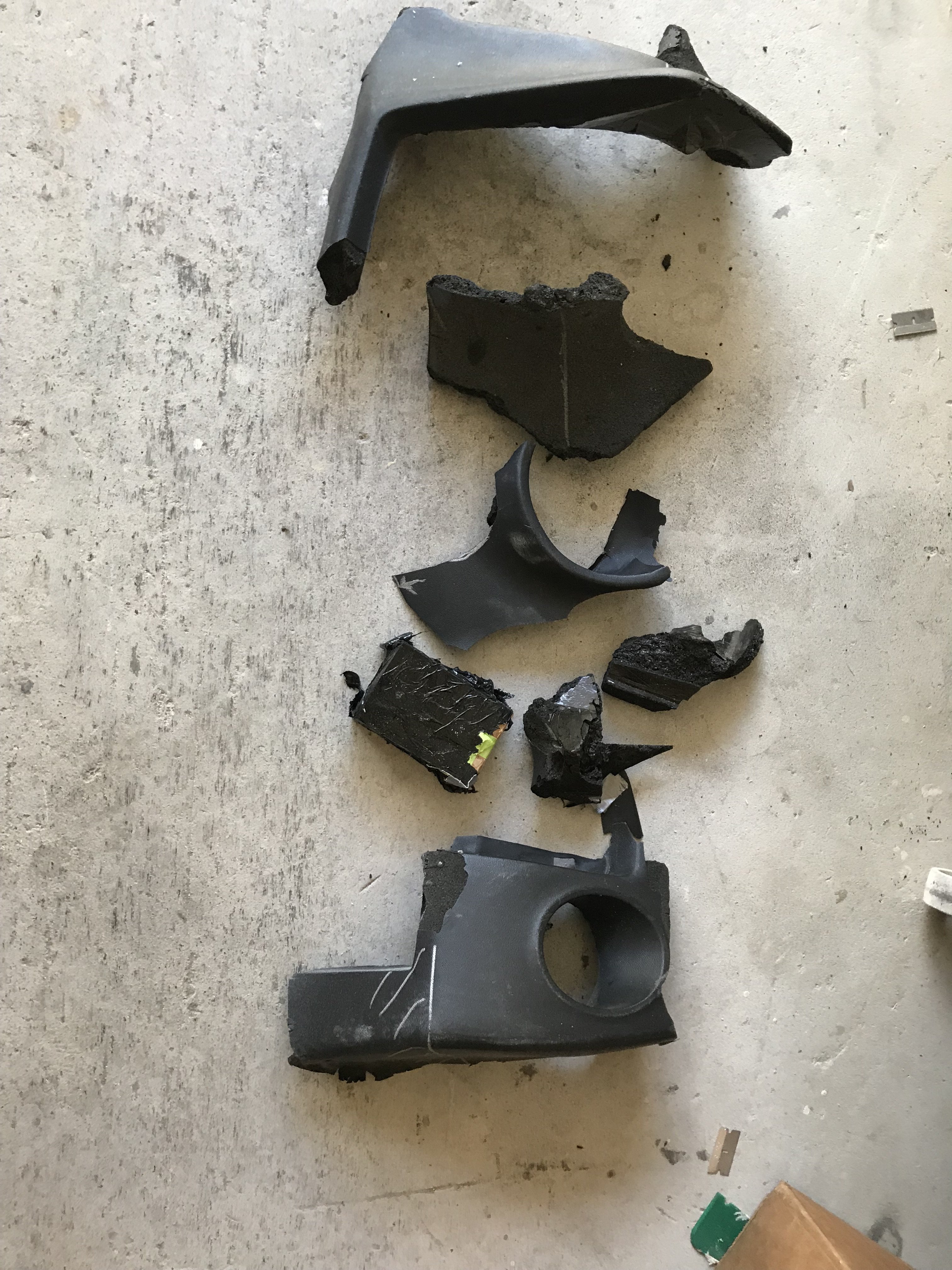
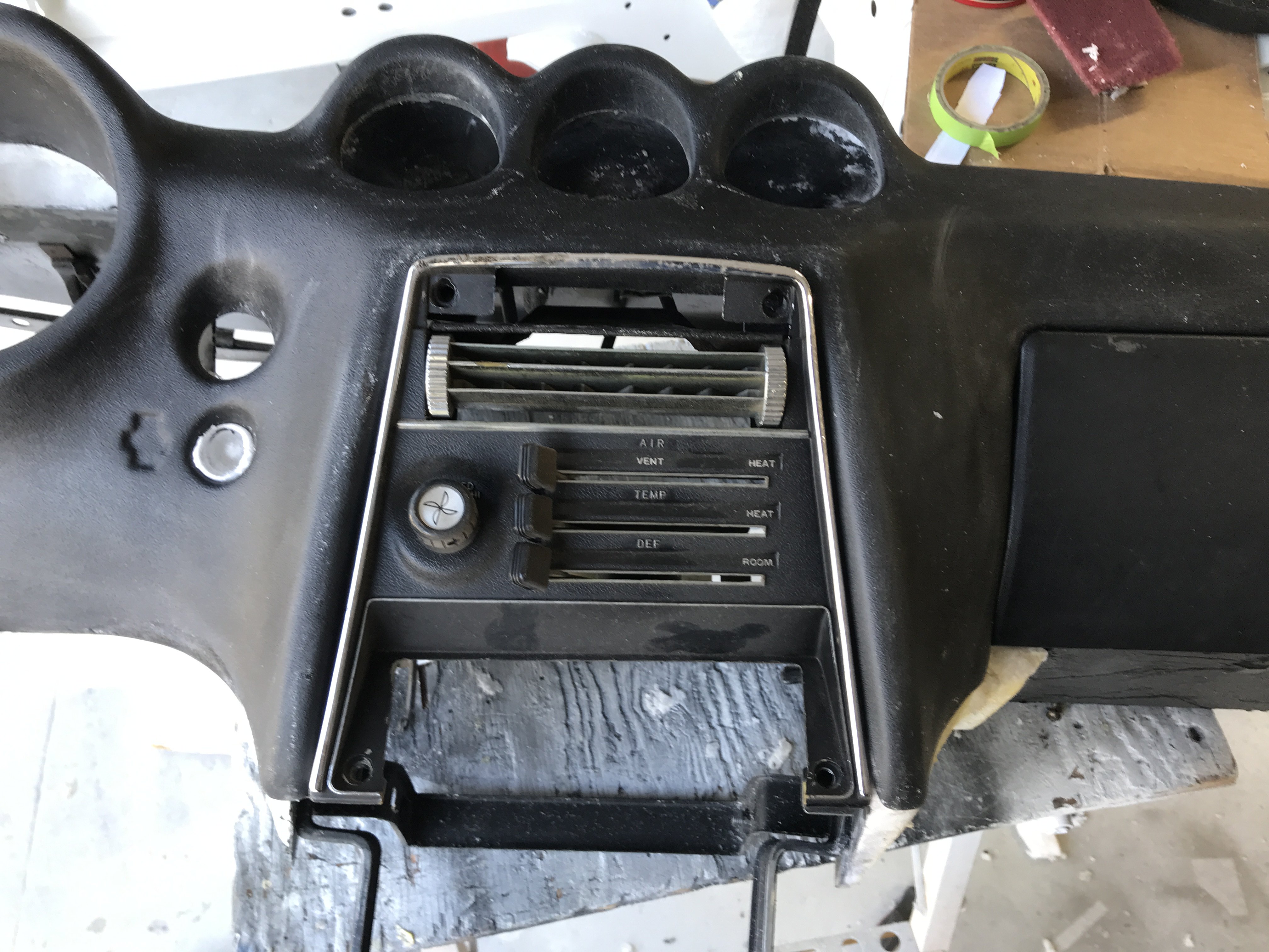
This is a picture of the original dash cover for those of you who came to this post late. The whole dashboard was in about 10 separate pieces.
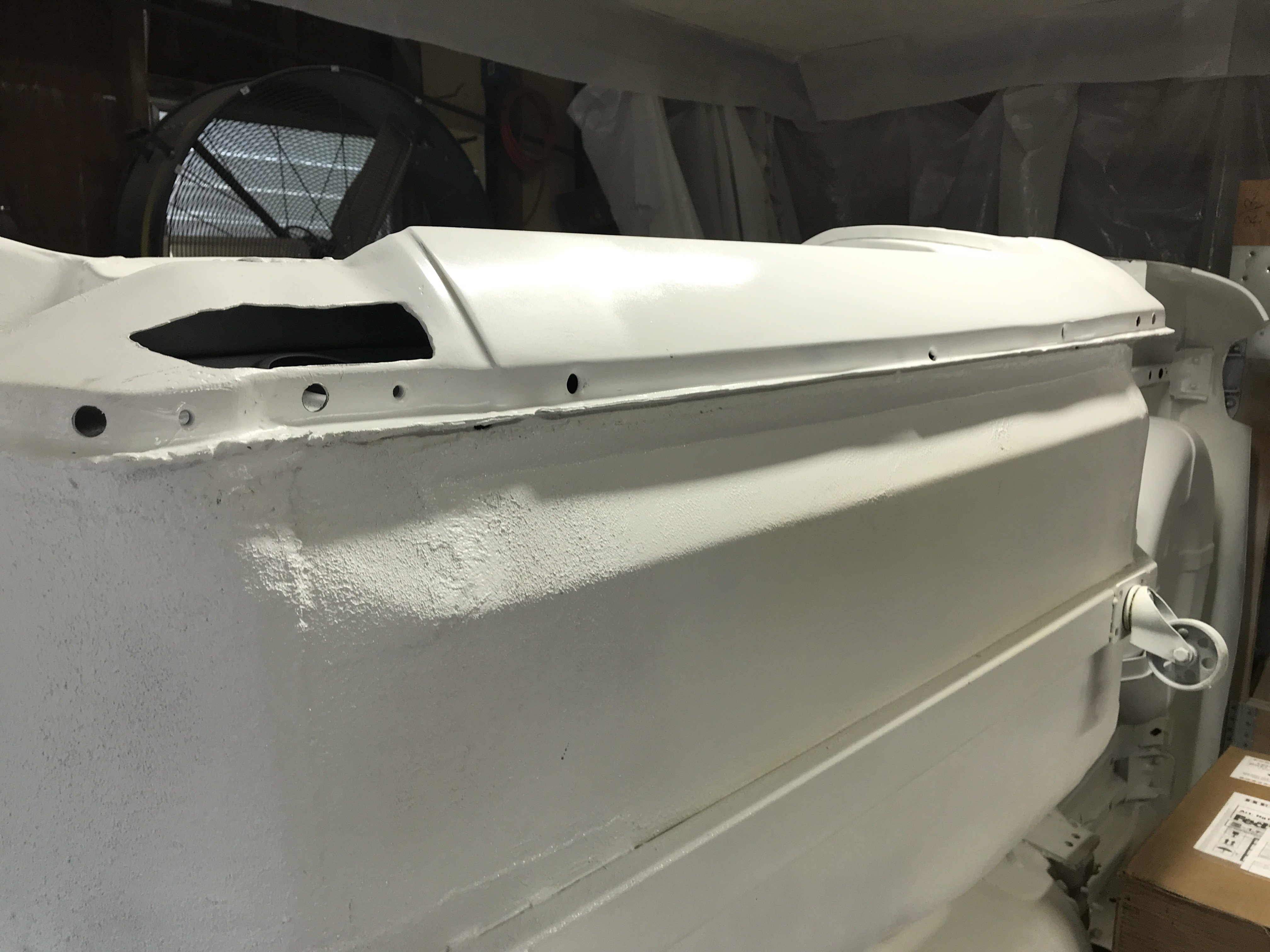
View of the repaired dashboard after a month of work.
Top View of Finished Dash Board.
Cnter View with Center Section and Glove Compartment installed
Closeup View of Glove Compartment Emblem
I decided the Emblem needed more "POP" so I brushed painted the Emblem with 3 colors-Red, Blue and Silver.
Note-The instrument Gauges(Speedometer, Tach and cluster gauges were not installed. I have not decided on what brand of gauges to use yet.
Am thinking about Speed Hut but still not sure. I left a lot of space around the gauges in case I decide on larger diameter gauges. The total
cost of materials is Motorsport Full Dash Cap-$120, 5 can 0f Loctite Foam-$25, one pint of Rigid Foam/Harder-$30, Black Trim Paint-$12 and
Sem Texture Coating-$35=$222.00.
How is the Replacement Dash Covers from Vantage Dash? If their price is still about $800 and quality is decent, it is worth the price.
I still have to finish the glove compartment box then off to the next challenge-Powder Coating.
.
-
Thanks for the kind words. I found that an old hacksaw blade with fine teeth worked well at cutting the excess foam away.
Note-The smooth cut of the foam.
This is my Rubbish Box for just this dash board project,
After trimming the excess foam from the front edge of the dash, the molding is installed to check the alignment.
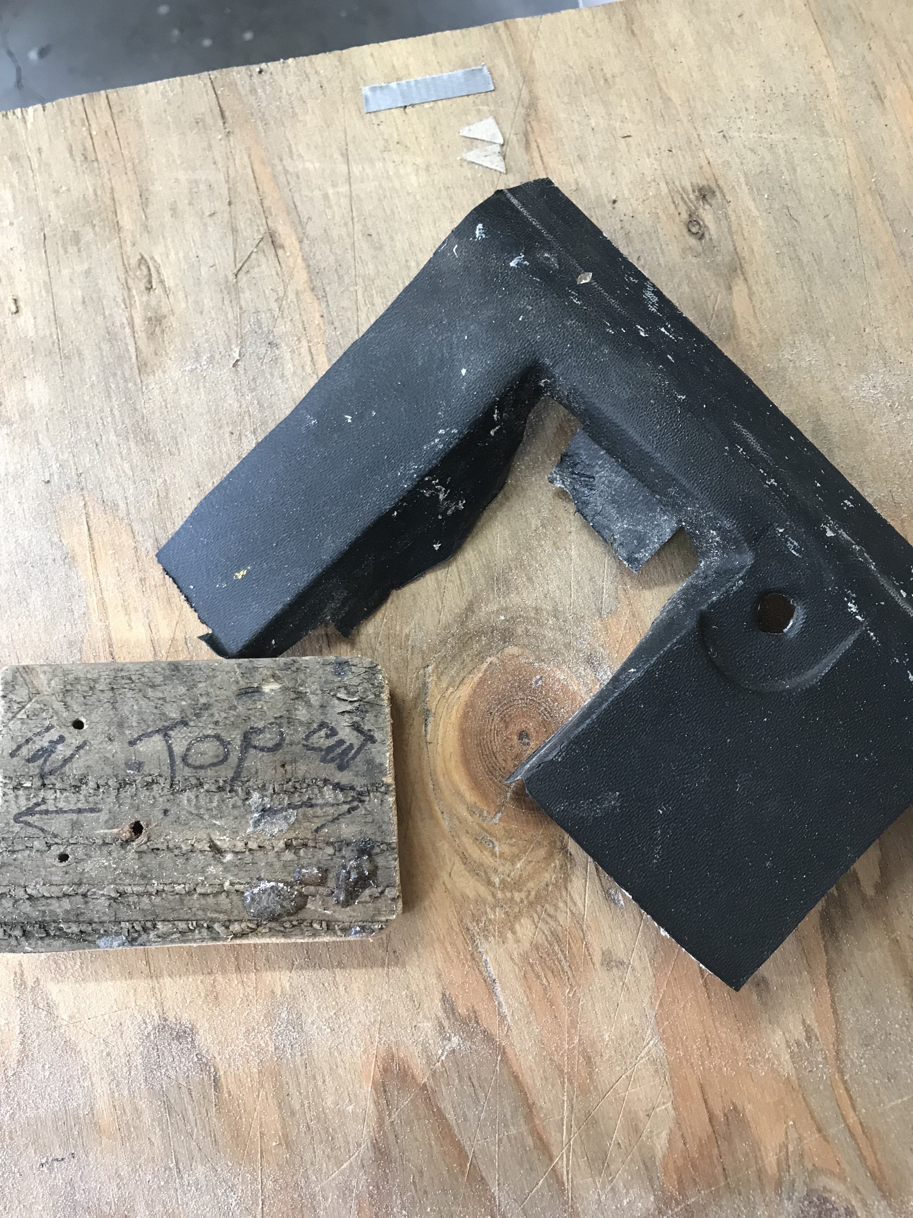
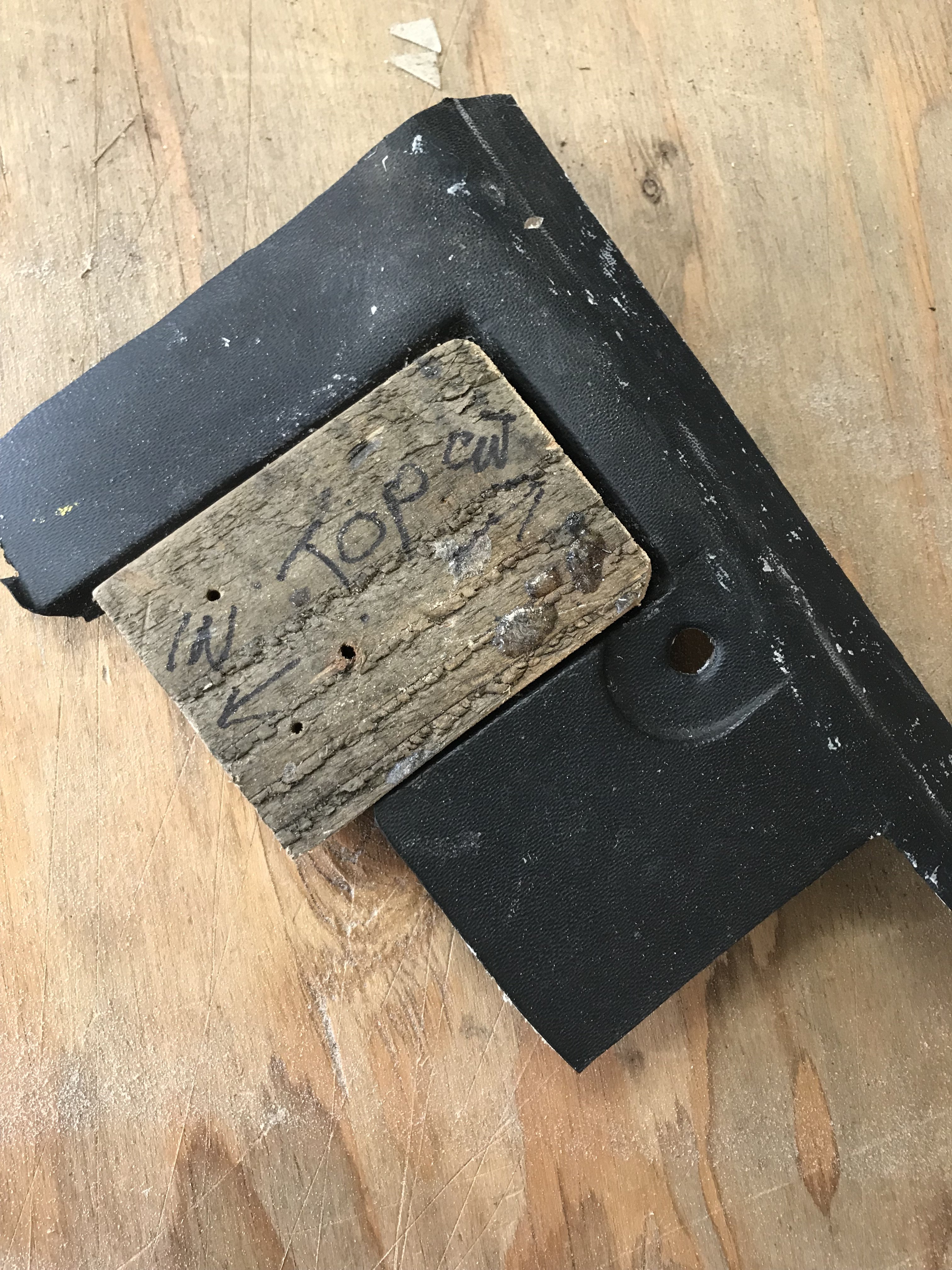
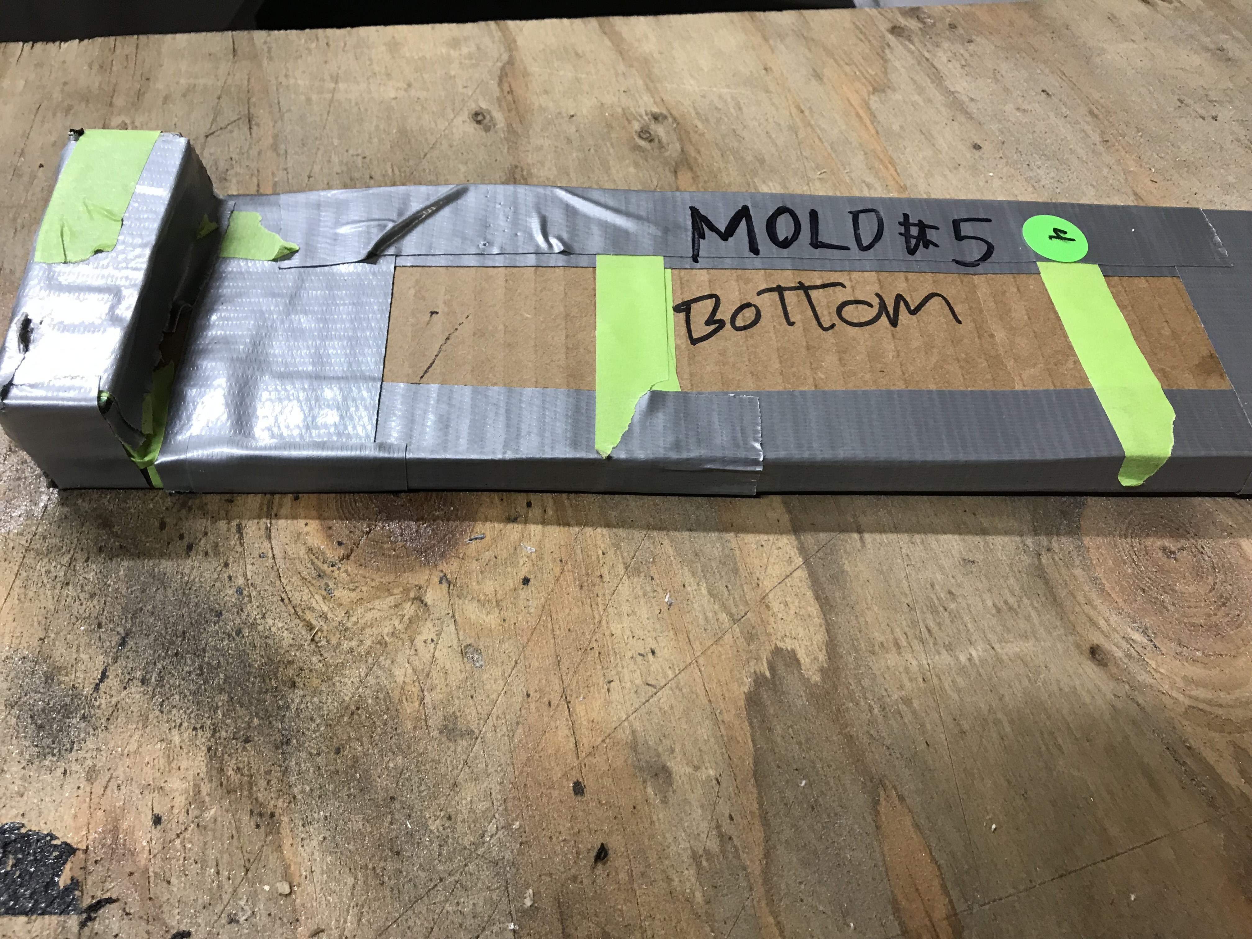
The bottom mold on the glove box was not strong enough to hold the foam so I made a stronger design.
The wooden block added the extra support to the mold,
Vise grips were used to hold the mold to the dash while welding.
The Center dash panel was test fitted into the dash,
Mold #5 was created to replace the foam section below the glove compartment.
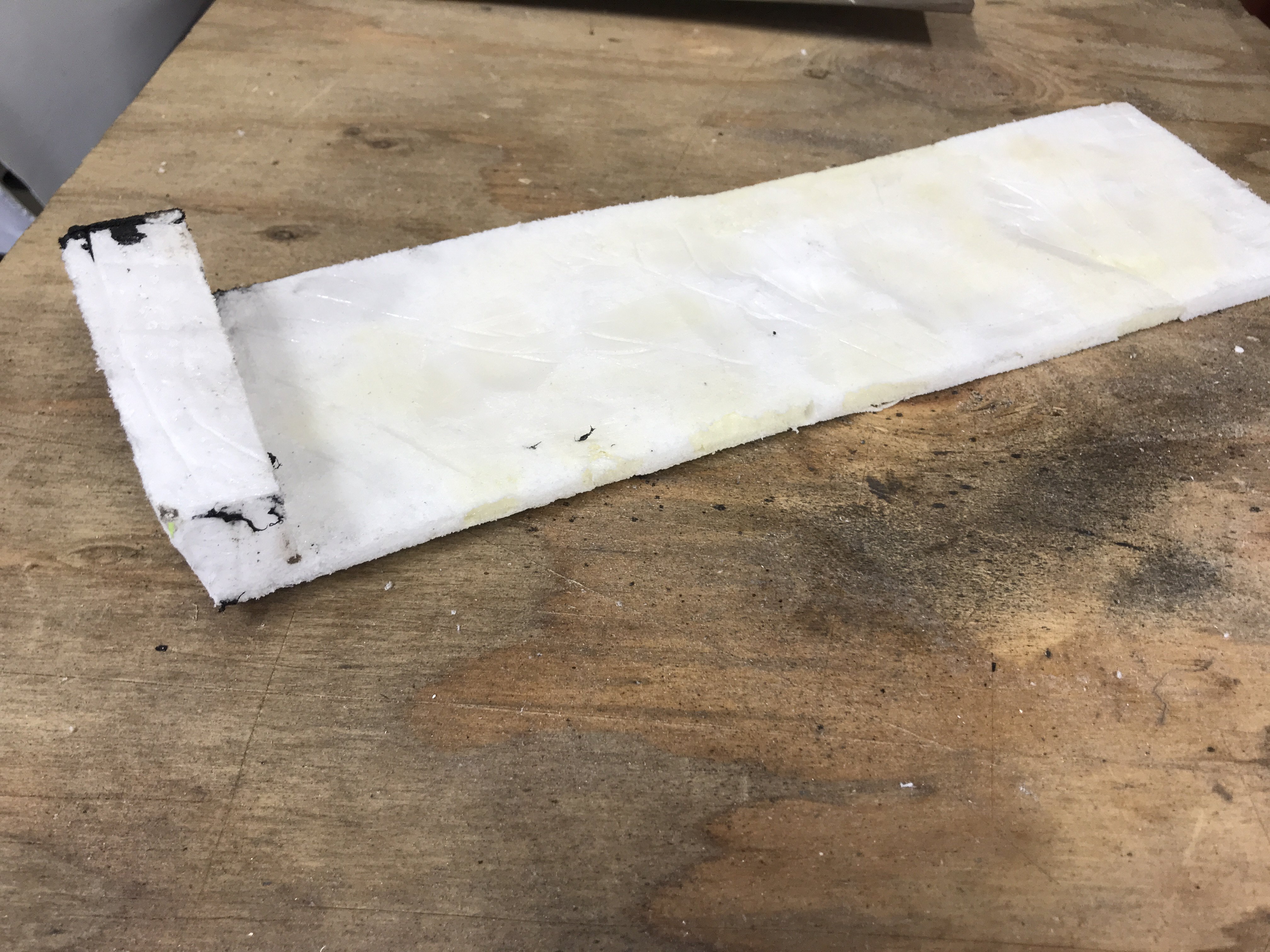
After removal from mold and trimmed.
Note-Its thinness and dfferent thickness of both longsides.
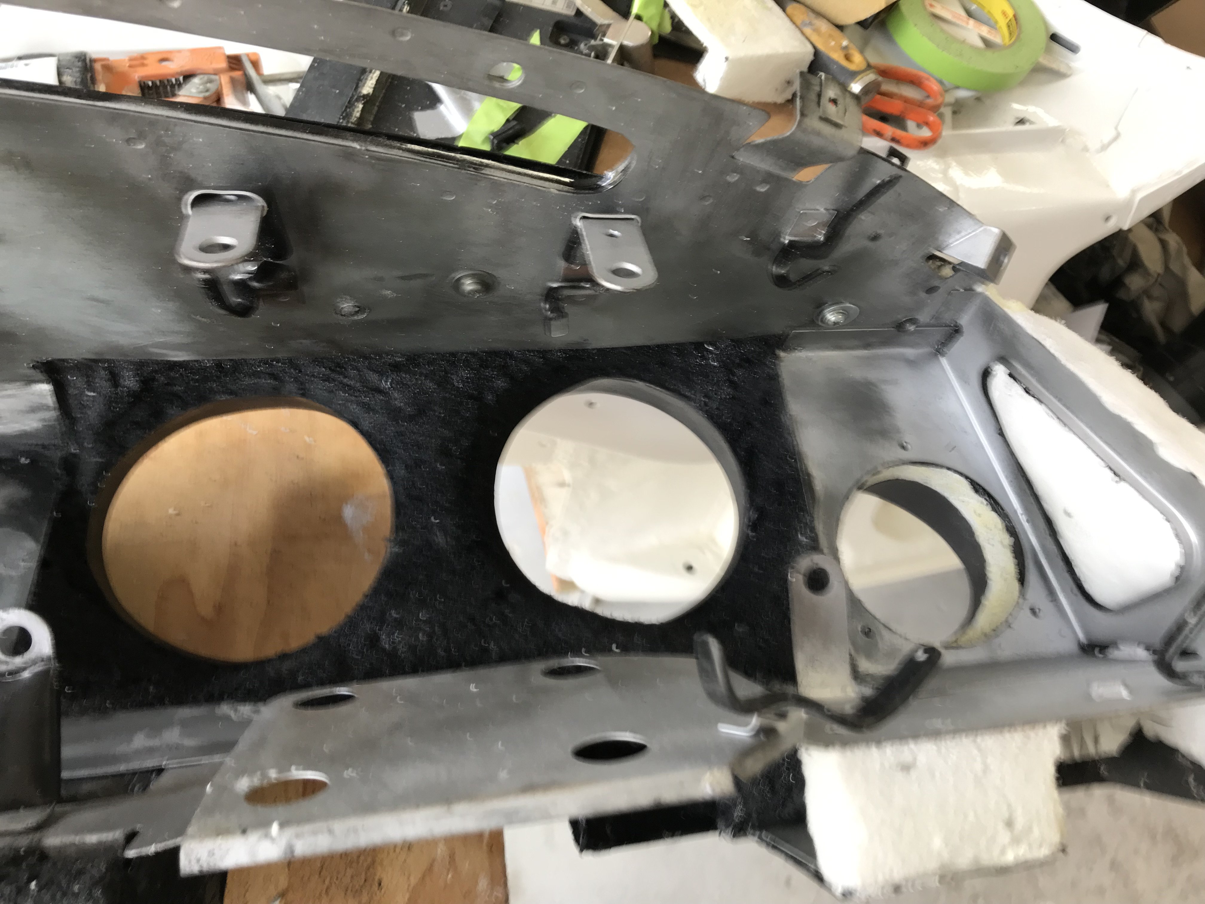
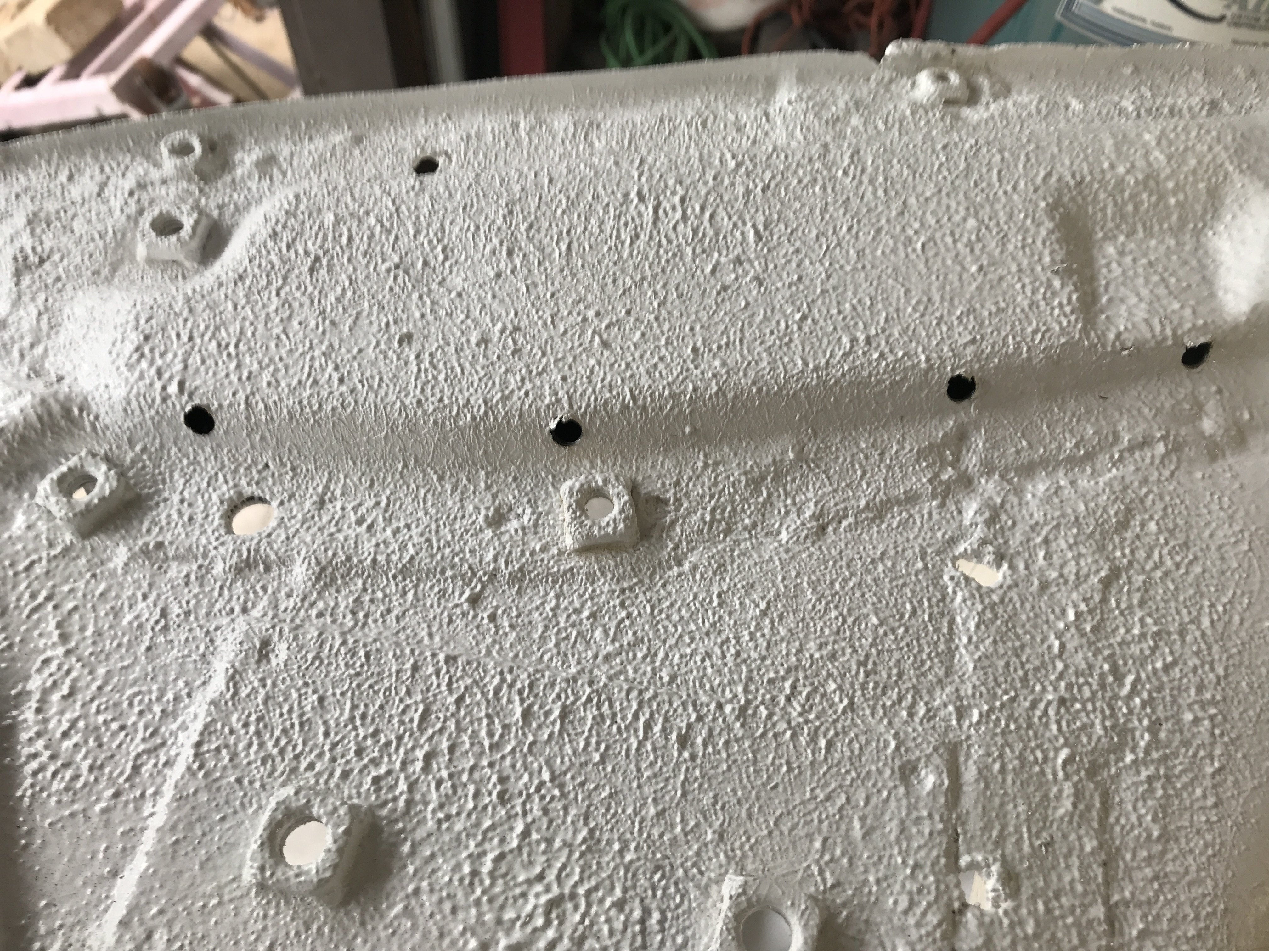
Bottom view of the glove compartment side of dash.
Center bottom view of the dash.
Bottom view of the Speedometer side of the dash.
Front view of Speedometer side of dash
While waiting for the form to cure, I constructed a replacement glove compartment box out .060 aluminum sheet;
side view front view
The replacement Glove Box was not replicated as I felt aluminum would better suited than a cardboard one. The sides of the box have not been installed as I am planning to line a gray Velour material on the inside of the box. Putting the fabric first without the sides on will make the job easier.
All of the exterior foam sections will probably be coated with Fiberglass Finishing Resin to give them more strength. Then, the dash will painted with a textured Dash Black paint so the glove compartment door will match the rest of the dash board.
-
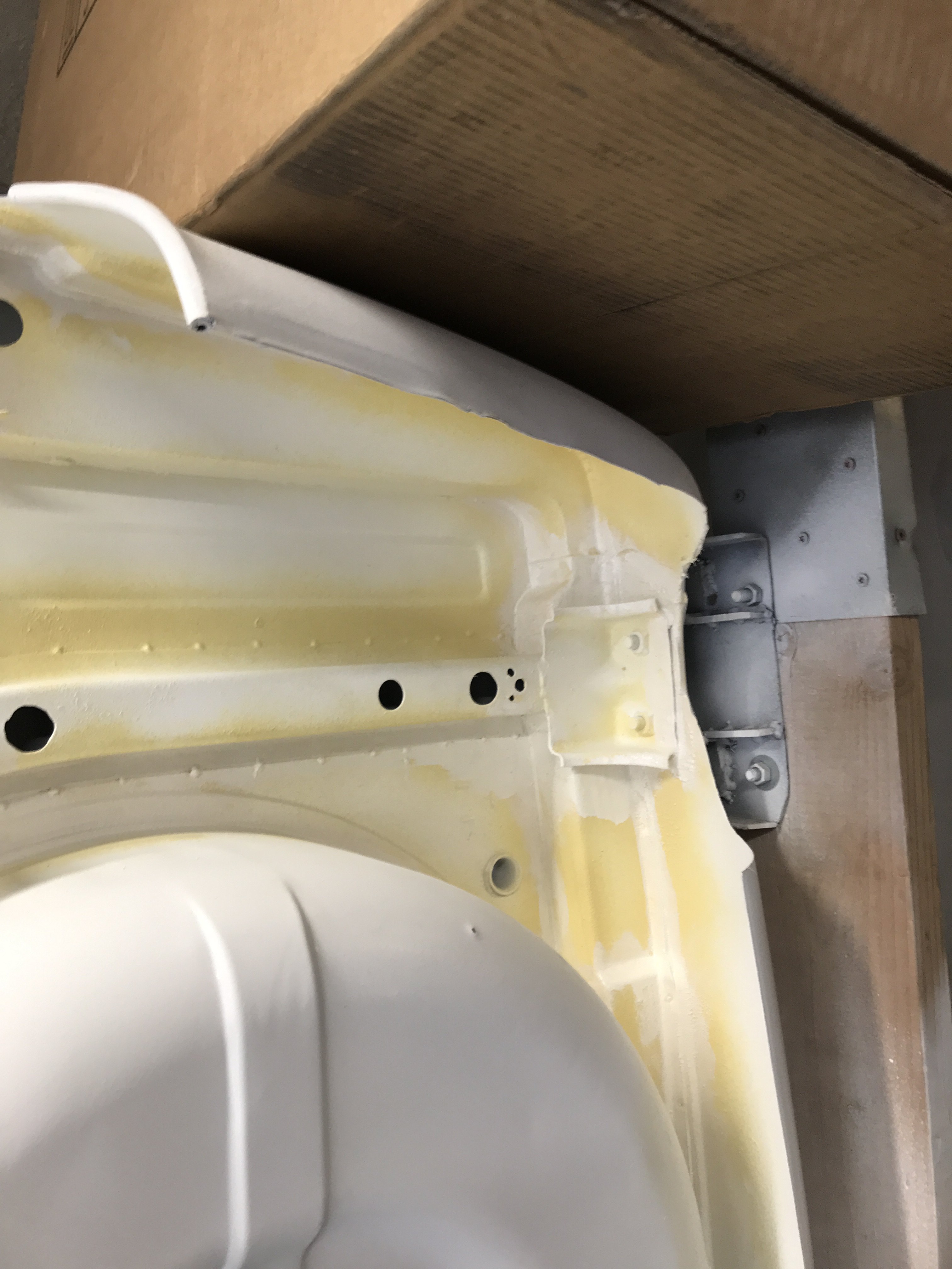
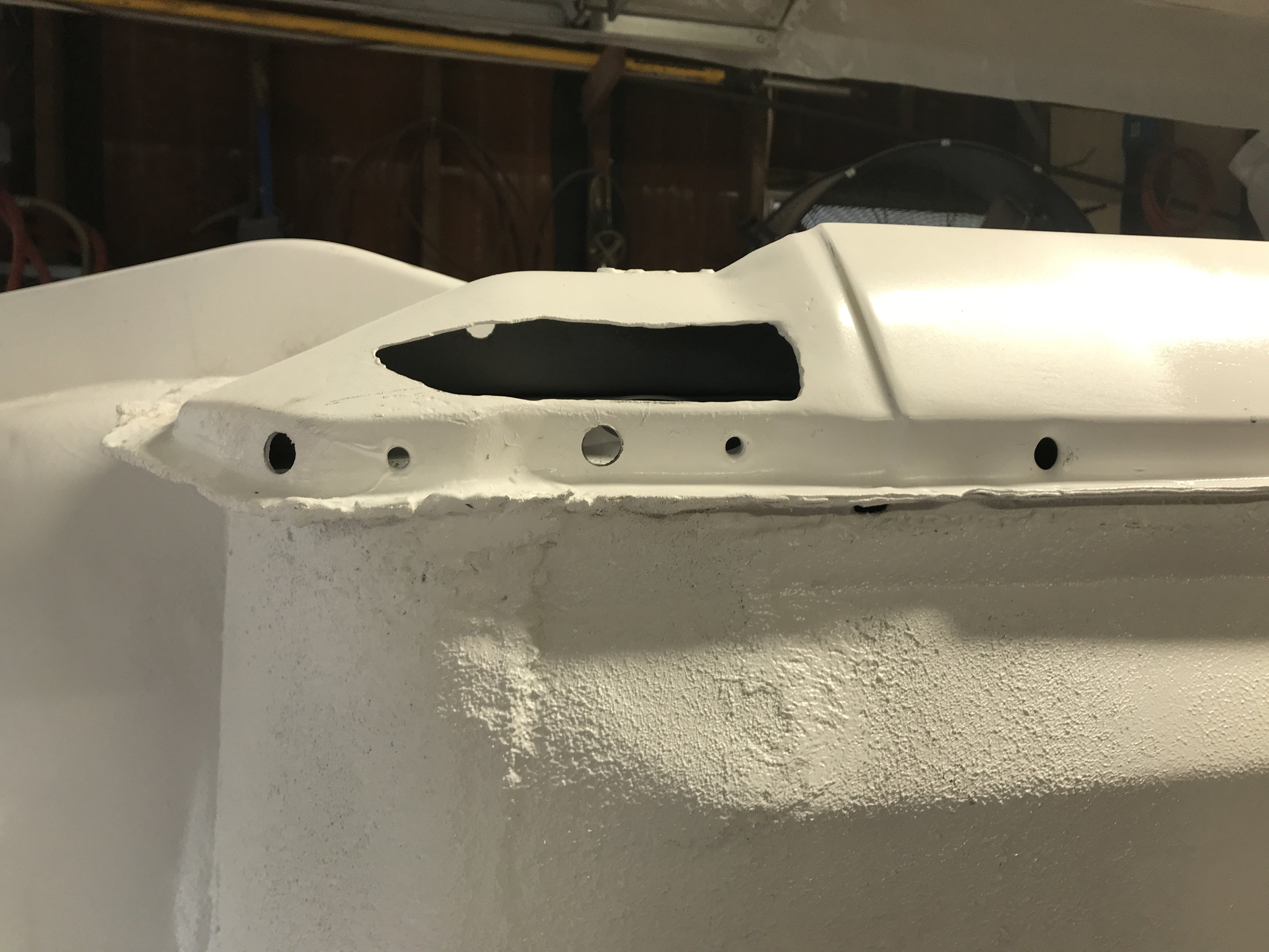
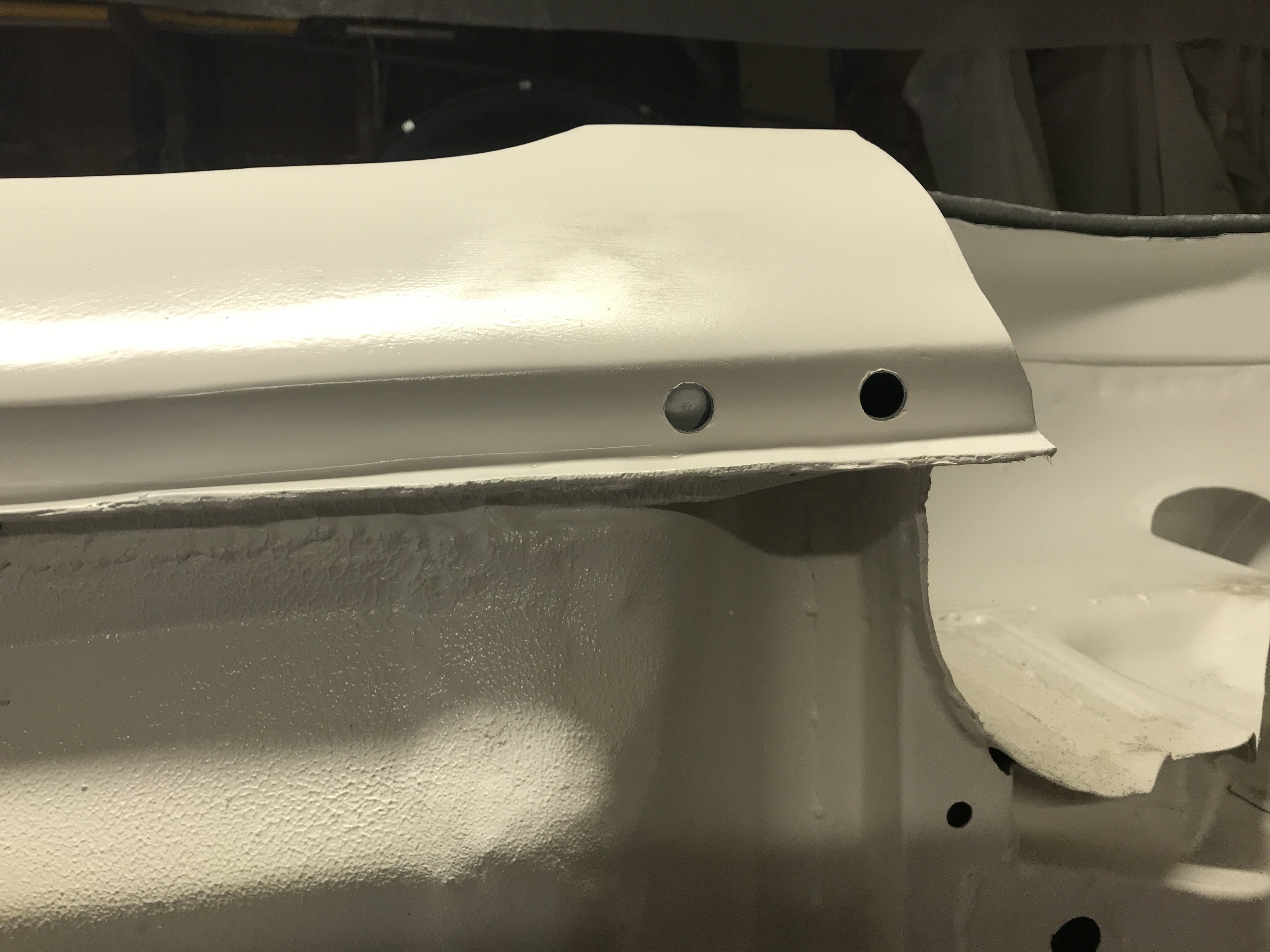
Four 1/4" holes were drilled in the dash to provide inspection ports in areas to check on foam movement.
The lower hole shows the foam coming through the dash.
The foam temperature was also monitored with a Infrared thermometer.
Inside section being epoxied together using vise grips.
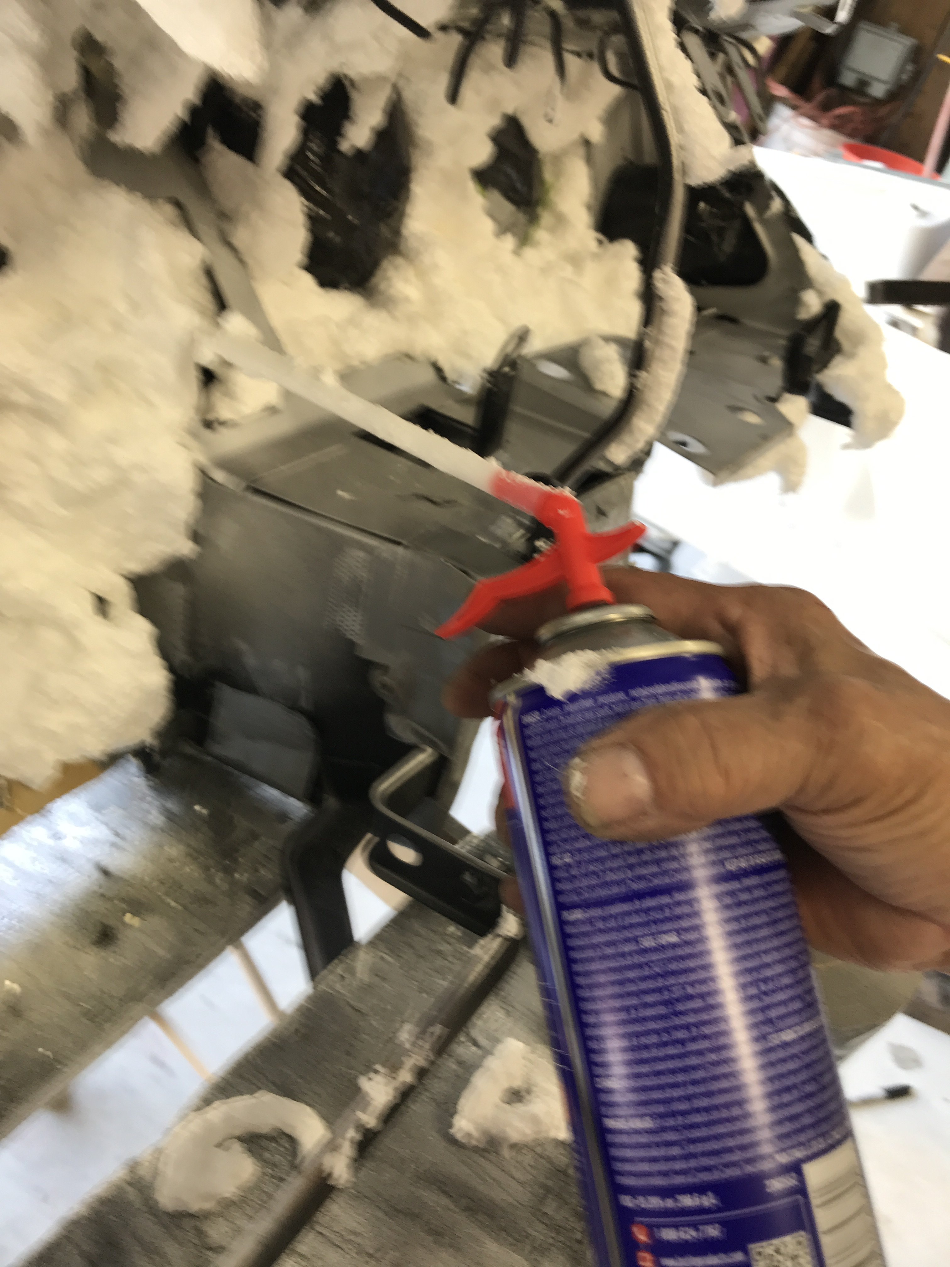
Locktite Tite Foam is a foam which expands a lot and should work perfectly for this project. Make sure to wear gloves and safety googles. This stuff is really sticky!! So
keep lacquer thinner or acetone nearby to clean up with. The flexible nozzle helps to get into confined areas.
Purchased from Home Depot for about $5 a can.
There are several places to check dash cap alignment before foaming.
Check gap and height alignment here.
Another point of alignment is the glove compartment lock hole.
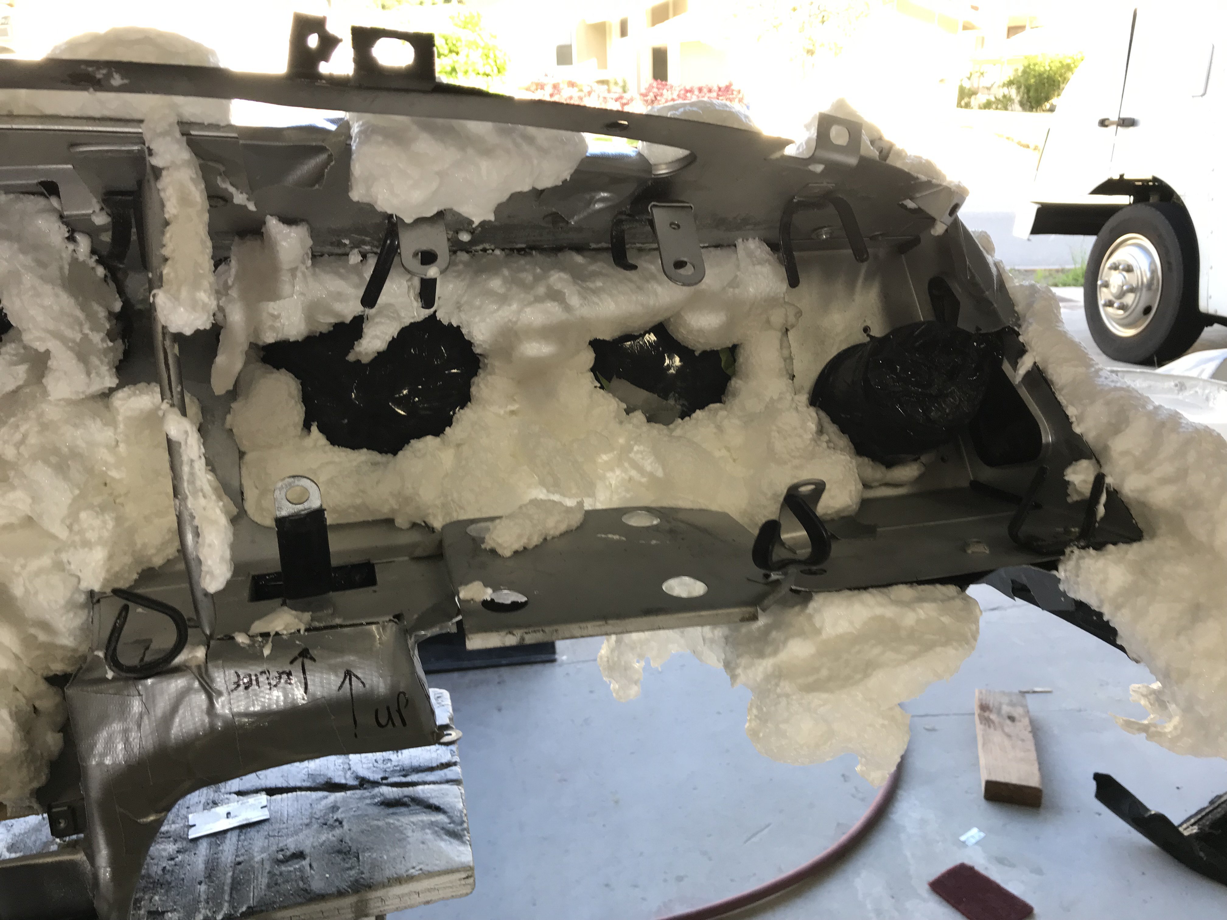
Crumbled paper wrapped with black plastic sheeting was used to plugged gauges, speedometer and tach openings.
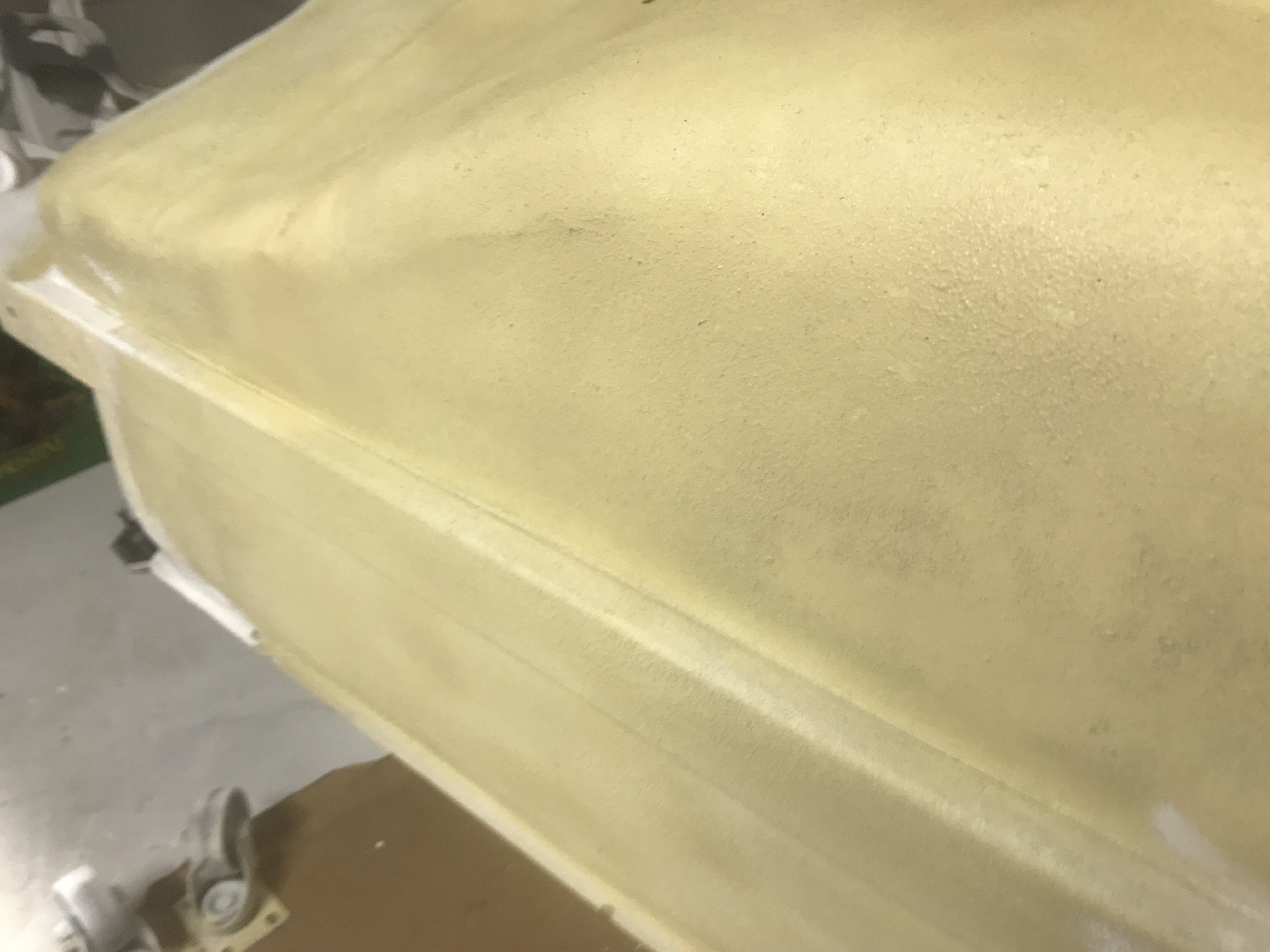
Now the foaming can begin. I started with the top area of the dash as it is the most visible and the most likely to deform.
Note-Allow time for foam to expand before spraying more.
It will expand more than you expect especially this Locktite Tite Foam.
Have to wait 24 hours for the foam to fully cure before cutting away. Probably be using a Dremel, utility knife and razor blades to cut excess foam all.
.
-
My dashboard was in bad shape as most of its early life( 71 to 83) it was parked outside all the time. This picture shows the dashboard broke into eight pieces when it fell off the work bench.
Note-Huge cracks through out the dash board
So first thing to do was to sandblast the small amount of corrosion of the frame of the dash.
My Speed Blaster does a good blasting job on objects to bigger to fit in my sandblasting cabinet.
Motorsport supplied the replacement dash cap for $120 as the old dash foam was so bad it would just crumble in your hands. So I decide to replace the dash foam with new stuff. So I decide to use the Motorsport dash cap and the existing dash frame as a mold. Then new foam would poured or injected into this mold.
So now I had to seal off the metal part of the dash to be a part of the mold. Black shipping sheeting was utilized to wrap the dash. 3M General Spray Adhesive would sprayed on the hold the sheeting in place.
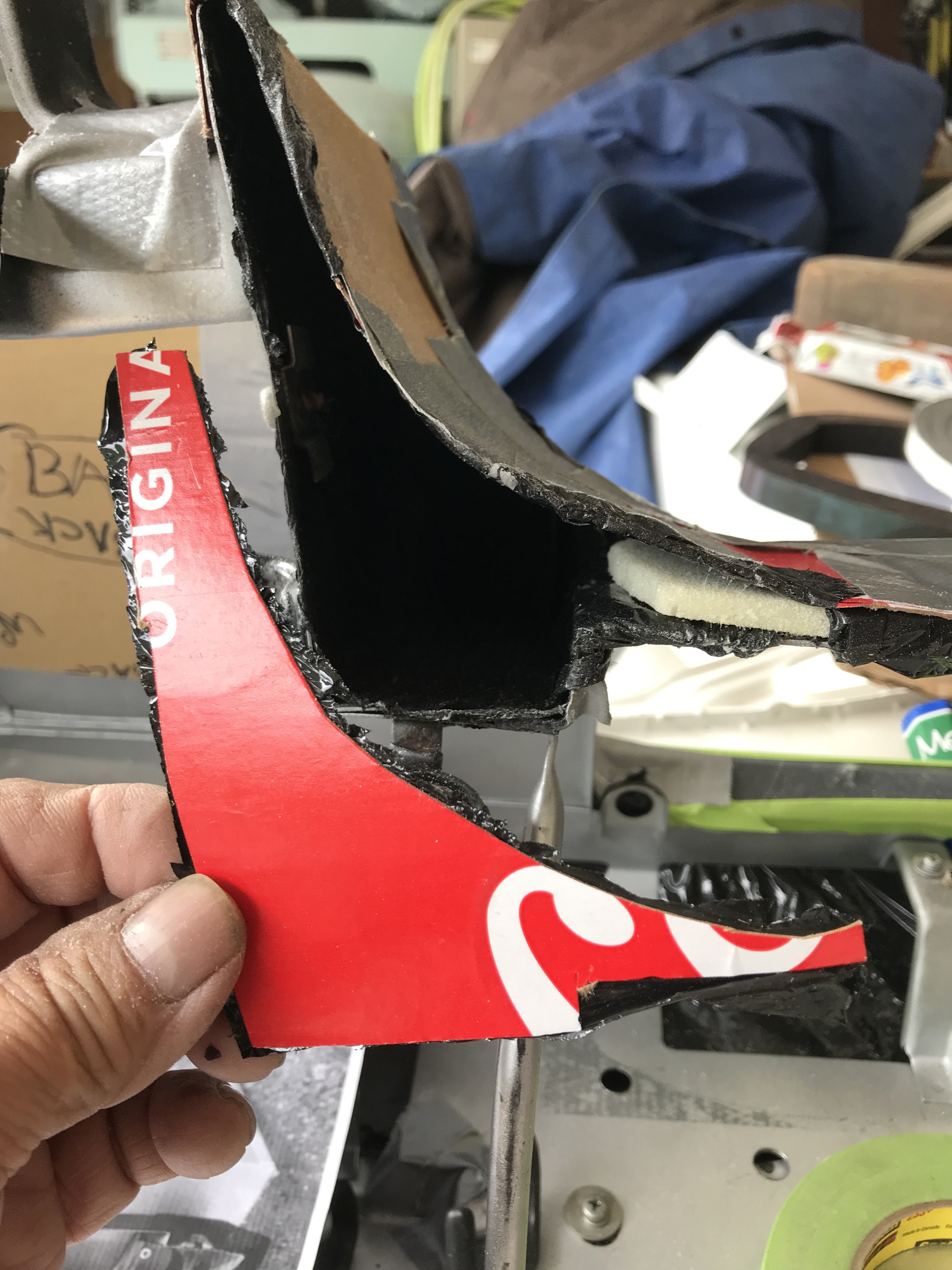
The biggest problems was the Motorsport replacement dash cap did not cover the lower section of the dash board. Four major molds would have to be created to fill in these areas. Using card board and duct tape were used in this process. The inside of the card board would be covered with the black sheeting to provide easy removal from the mold. There were some of the original dash sections that could be reused.
View of the Right lower section of dash
This corner section was sectioned off the original dash then epoxied to the replacement cap.
The other part of this patch
.
Center panel mold outside view
Note=Black sheeting inside of the mold
The outside view of the mold
A lot of Duct Tape created a sturdy mold.
The left side mold was constructed the same way
Note -Bottom of the mold was left open otherwise the foam pressure would distort or damage it.
This view shows the mold attached to the replacement dash cap with duct tape.
-
My dashboard was in bad shape as most of its early life( 71 to 83) it was parked outside all the time. This picture shows the dashboard broke into eight pieces when it fell on the work bench.
Note-Huge cracks through out the dash board
So first thing to do was to sandblast the small amount of corrosion of the frame of the dash.
My Speed Blaster does a good blasting job on objects too big to fit in my sandblasting cabinet.
Motorsport supplied the replacement dash cap for $120 but the old dash foam was so bad it would just crumble in your hands. So I decide to replace the dash foam. I decided to use the Motorsport dash cap and the existing dash frame as a mold. Then new foam would poured or injected into this mold.
So now I had to seal off the metal part of the dash to be a part of the mold. Black shipping sheeting was utilized to wrap the dash. 3M General Spray Adhesive would sprayed on the frame to hold the sheeting in place. The biggest problem was the Motorsport replacement dash cap did not cover the lower section of the dash board. Four major molds would have to be created to fill in these areas. Using card board and duct tape were used to make the molds. The inside of the card board would be covered with the black sheeting to provide easy removal from the mold. There were some of the original dash sections that could be reused for this purpose
View of the Right lower section of dash
This corner section was sectioned off the original dash then epoxied to the replacement cap.
The other part of this patch
.
Center panel mold outside view
Note=Black sheeting inside of the mold
The outside view of the mold
A lot of Duct Tape created a sturdy mold.
The left side mold was constructed the same way
Note -Bottom of the mold was open otherwise the foam pressure would distort or damage it.
This view shows the mold attached to the replacement dash cap with duct tape.
-
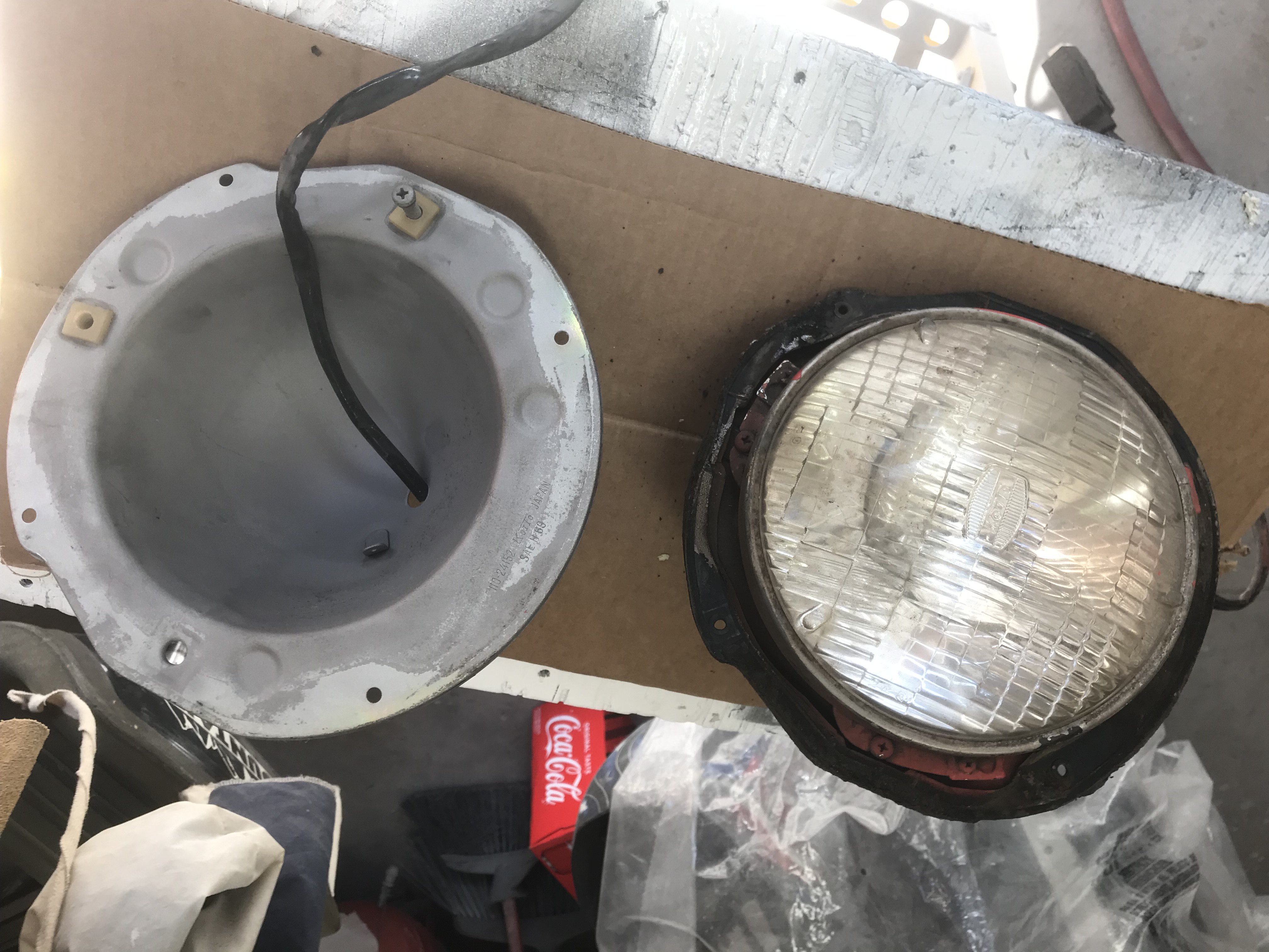
While awaiting some parts to come in, I decided to work on the two front headlight buckets.
Right bucket is "before cleaning" and left is "after cleaning"
The right bucket is "before cleaning" and left one is "after cleaning".
This pic shows both head light buckets with light mounting cups.
I was thinking of restoring these buckets with zinc chromate( yellowish gold plating) But found the zinc chromate is very toxic and hard to
dispose of. So I am thinking of trying using metallic gold powder coating to recreate the coating. Checking to see if I can match the color.
I ordered an Eastwood Powder Coating kit but it is on back order till February. So I went to work on the disassembly of the rear suspension.
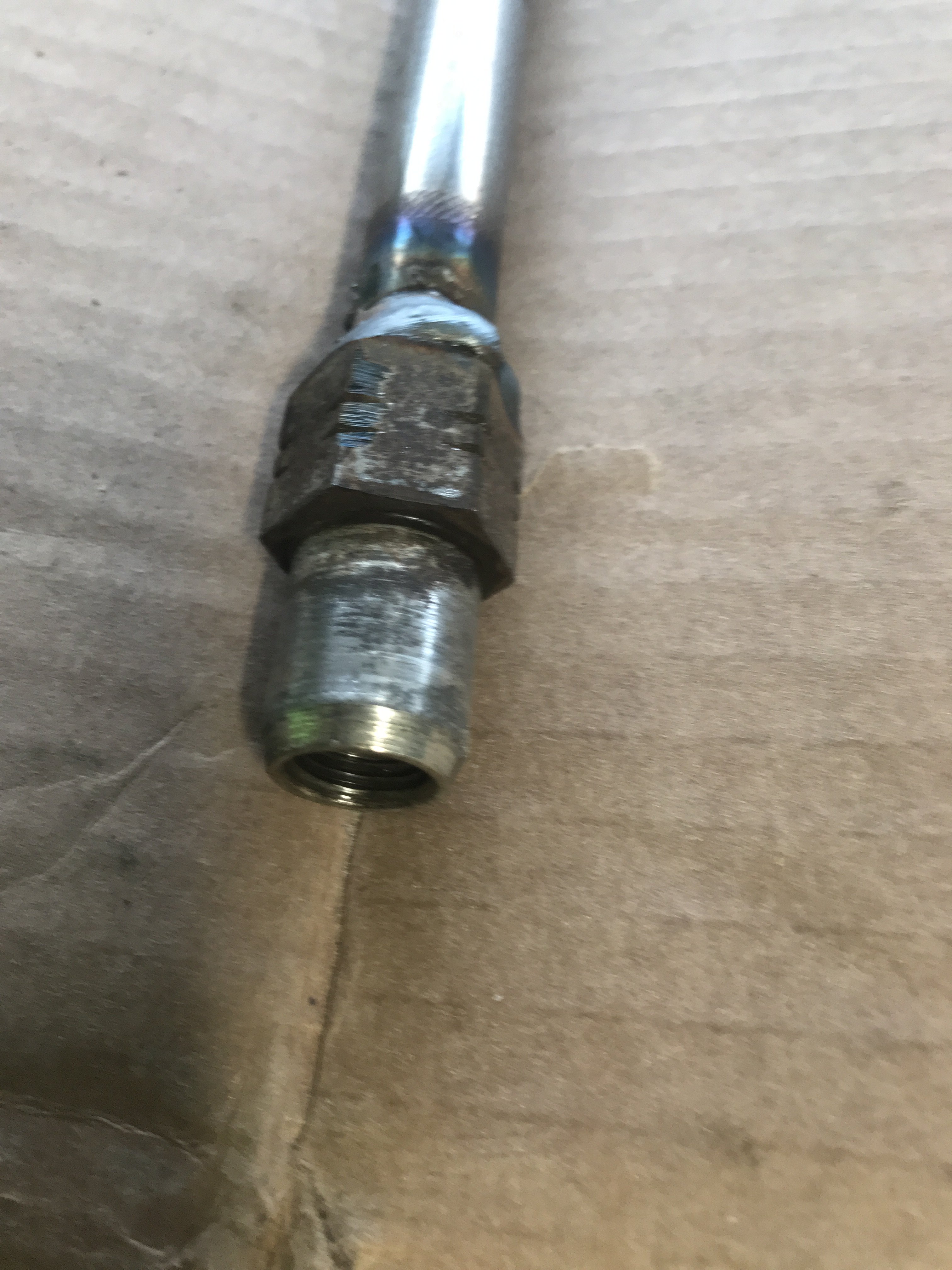
Of coarse, the most difficult part is the removal of the spindle pins. In our tropical climate here, I knew those pins would not slide easily. As
I didn't want to spend $100 for the puller + freight, I decided to fabricate one. Went to Home Depot to gather all the parts.
First, I migwelded a used wheel lug nut (12mm X1.25) to my 5/8" NC X14" threaded rod for the pulling screw.
total view of 14" pulling screw
Used a 1" ID steel fence post about 12" with 5/8" steel washer welded to one end of the pipe.
aaa
Note: the spindle pin shaft is on the top then the threaded pulling shaft then the pipe housing on the bottom. The threaded rod was screwed securely to the threaded end of the spindle pin. The round housing was installed over the tjhreaded screw. Then two additional 5/8" flat washers with grease between them was added to provide slippage under tension( a small bearing
can be used too). Then the pulling nut is added.
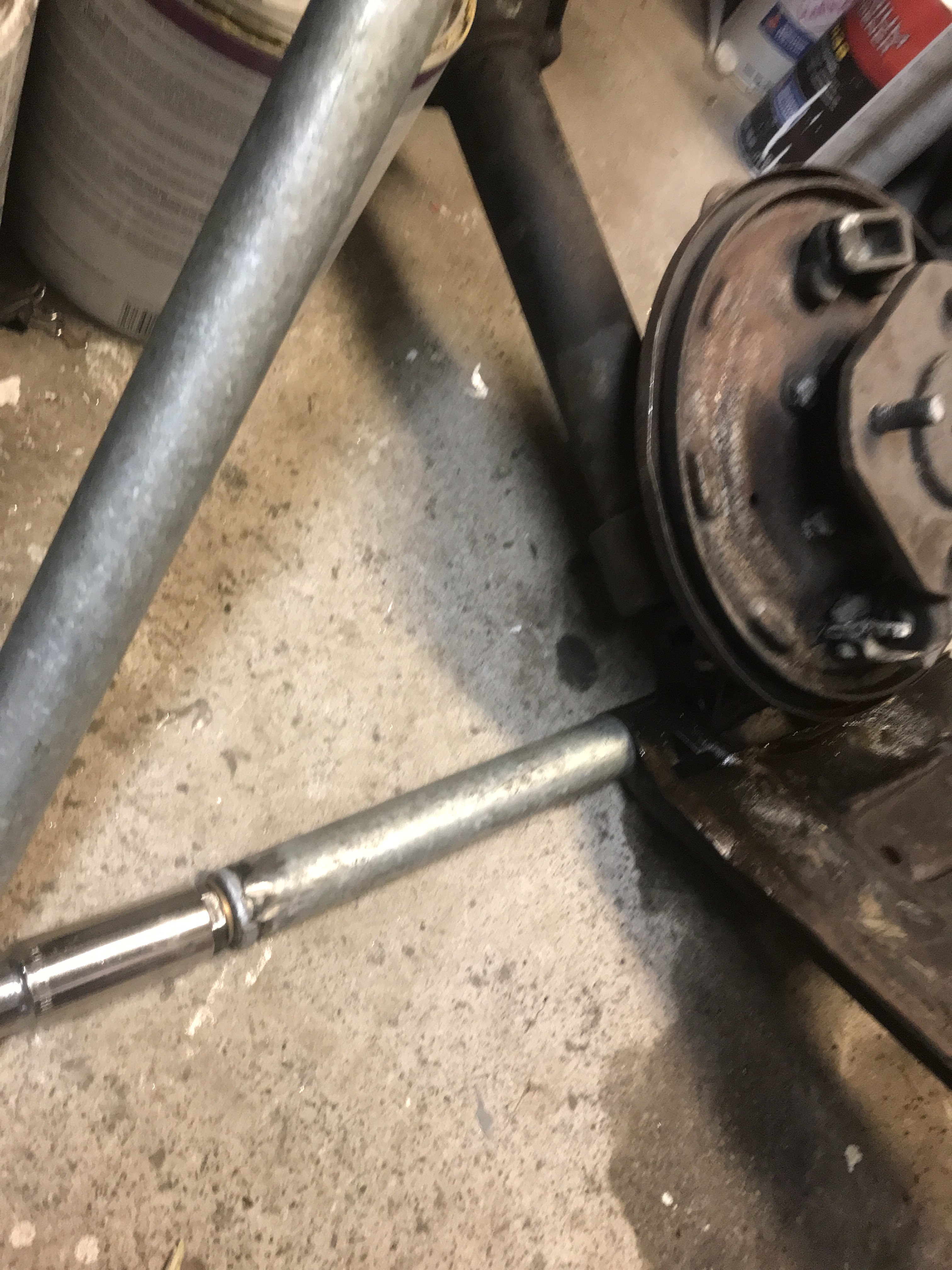
A 1/2 ratchet or 15/16" box wrench can used to turn down the pulling nut. For additional torque, a wrench extender or a long pipe can be utilized. Also, heating with a torch the cast iron area around the spindle locking pin will loose the corrosion
if it is really stuck.
Another important thing to make removal easier is the use of penetrating oil. After removing the two nuts and washers on both ends of the spindle pin, Place the suspension assembly so the pin is vertical as possible. Soak the top and between all
cracks to get the penetrating oil in as possible. I seen mechanics make a cup around the top of spindle to
create a reservoir to hold the oil. Leave the oil on as long as possible( even a week if necessary). The more oil that gets in,
the easier the job will be. It will take a long time to turn that nut to pull out that 11" spindle pin considering one rotation of the nut probably moves the pin about 1/16" to 1/8" out. It will seem that way.
The cost of the parts was about $20.
-
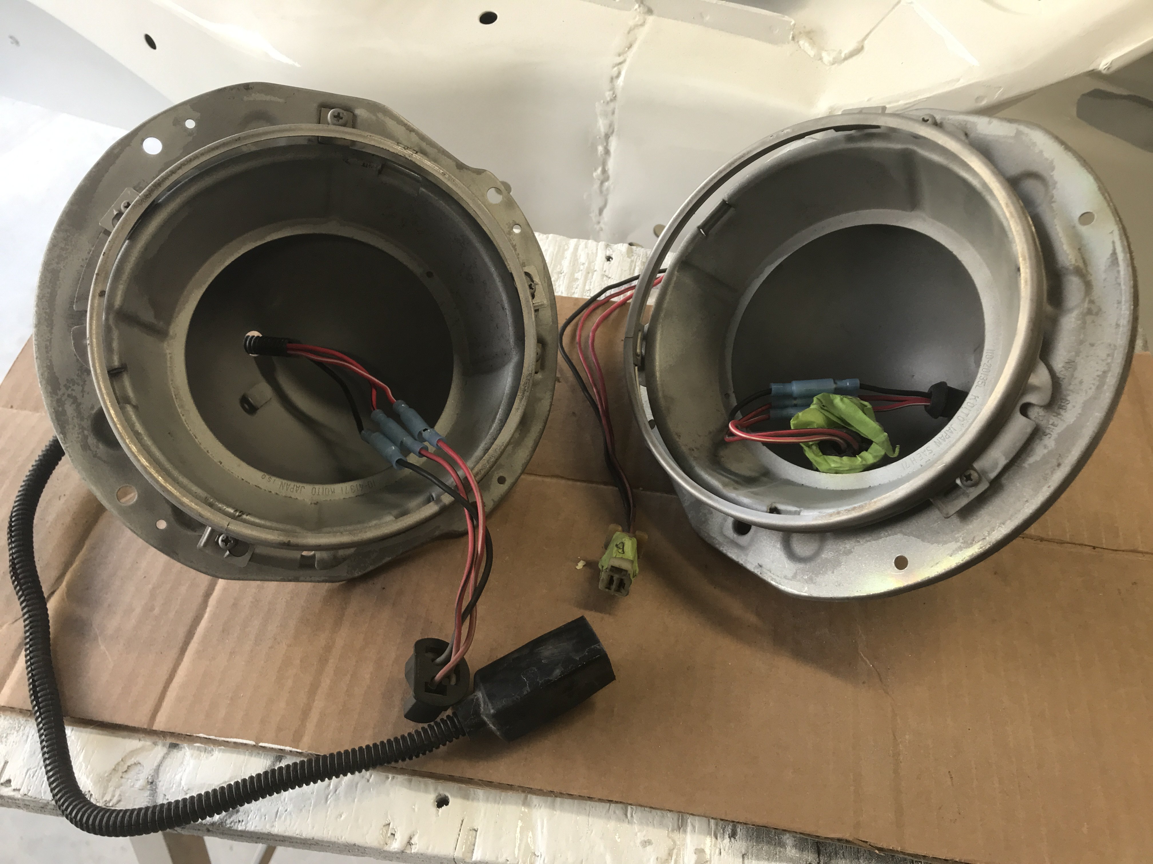
While I was waiting for some parts to come in, I decided to work on the two front headlight buckets.
A view of the back of the buckets. The right bucket is the "before cleaning" and the left is "after the cleaning".
The right bucket shows the "Before cleaning" an
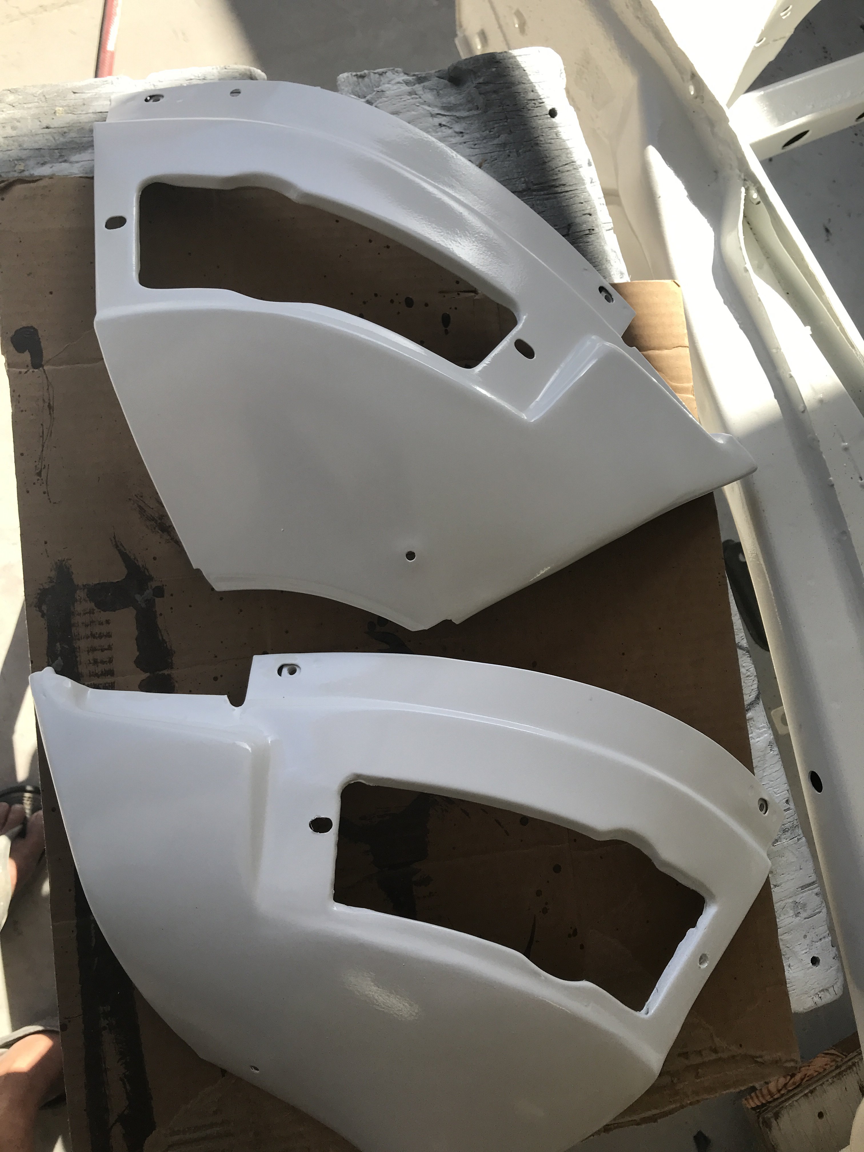
On 1/8/2019 at 7:41 PM, toolman said:View of the front lower bumper panels primed by poly primer.
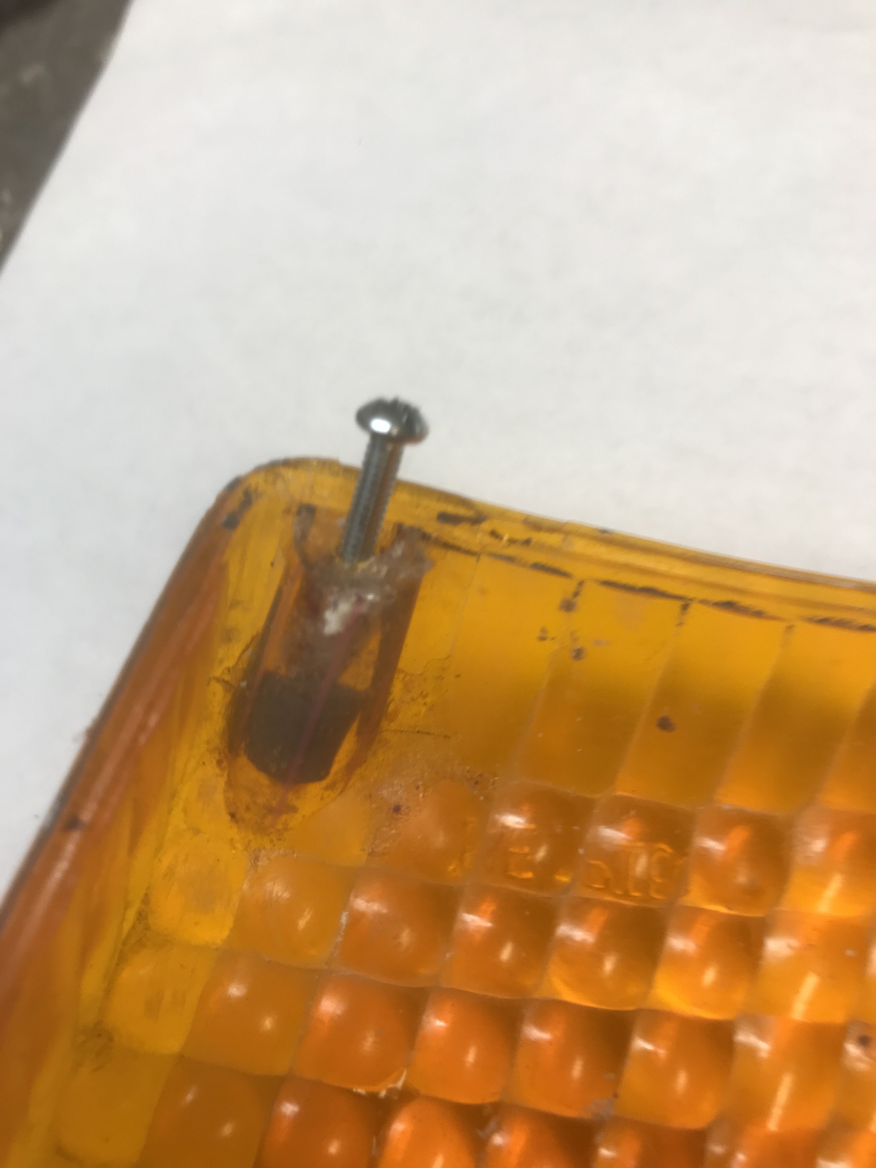
The bigger job was turned out to be the amber turn signal lens. Some of those tiny phillip screws(about 3mm) were rusted and had to be drilled
out.
Pic of broken lens mounting screws.
At first, I used gray JB WELD expoxy to repair those lens mounting plastic studs. Then upon putting the lens cover on the housing, the gray
epoxy created dark shallows in the lens. So I removed the gray epoxy and used
JB WELD Clear Epoxy was utilized to eliminate this problem.
The epoxy was dry to touch in a hour but waited till next day to drill and tap them.
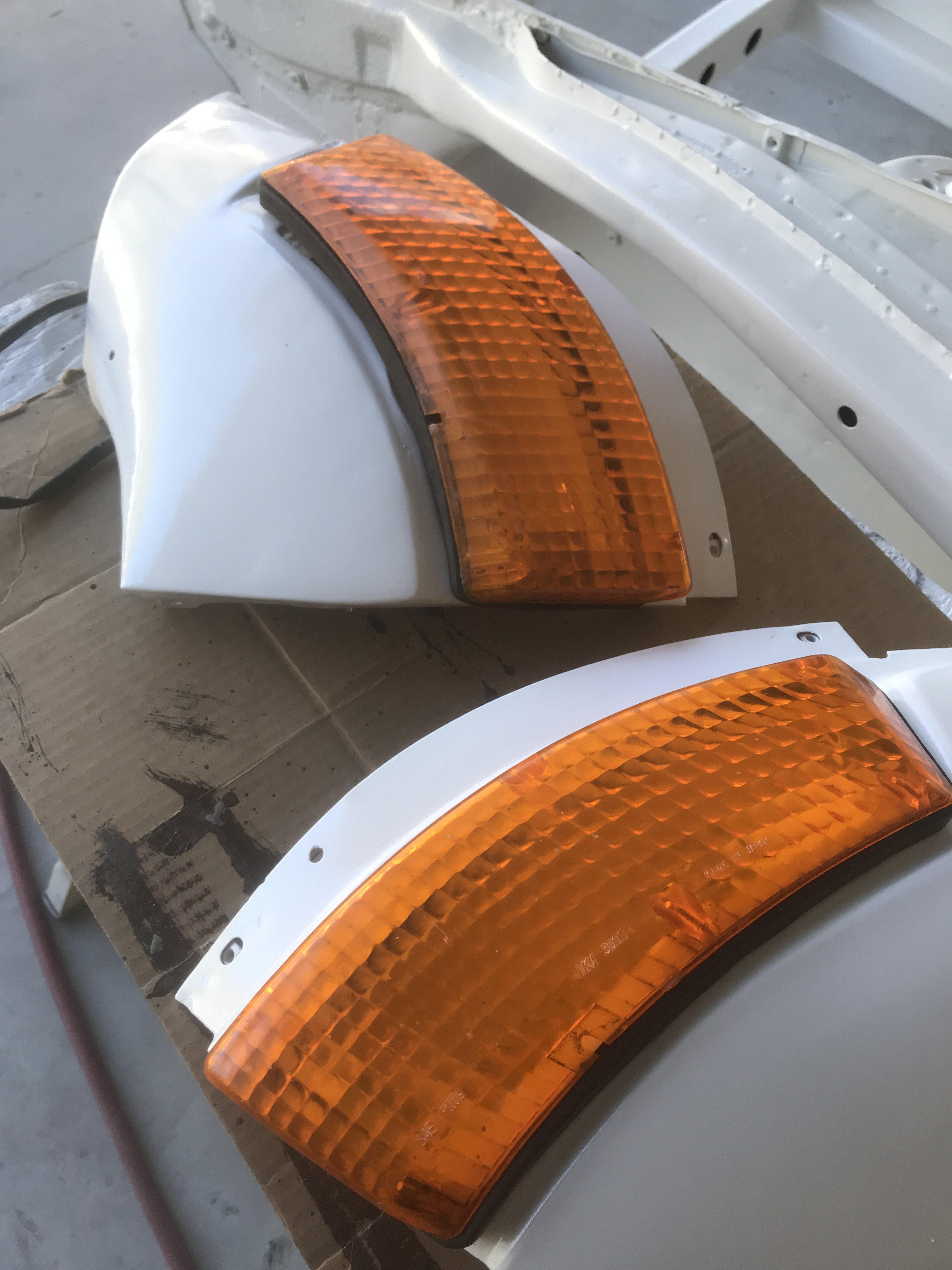
Those amber studs were recreated by using plastic straws and masking tape to make a mold for the epoxy. The straws were slit to go around
the existing studs. Masking tape was applied tightly to seal and hold the mold while curing. Phillips 4-40 screws was found to be close enough to
replace the rusted ones.
The finished product
-
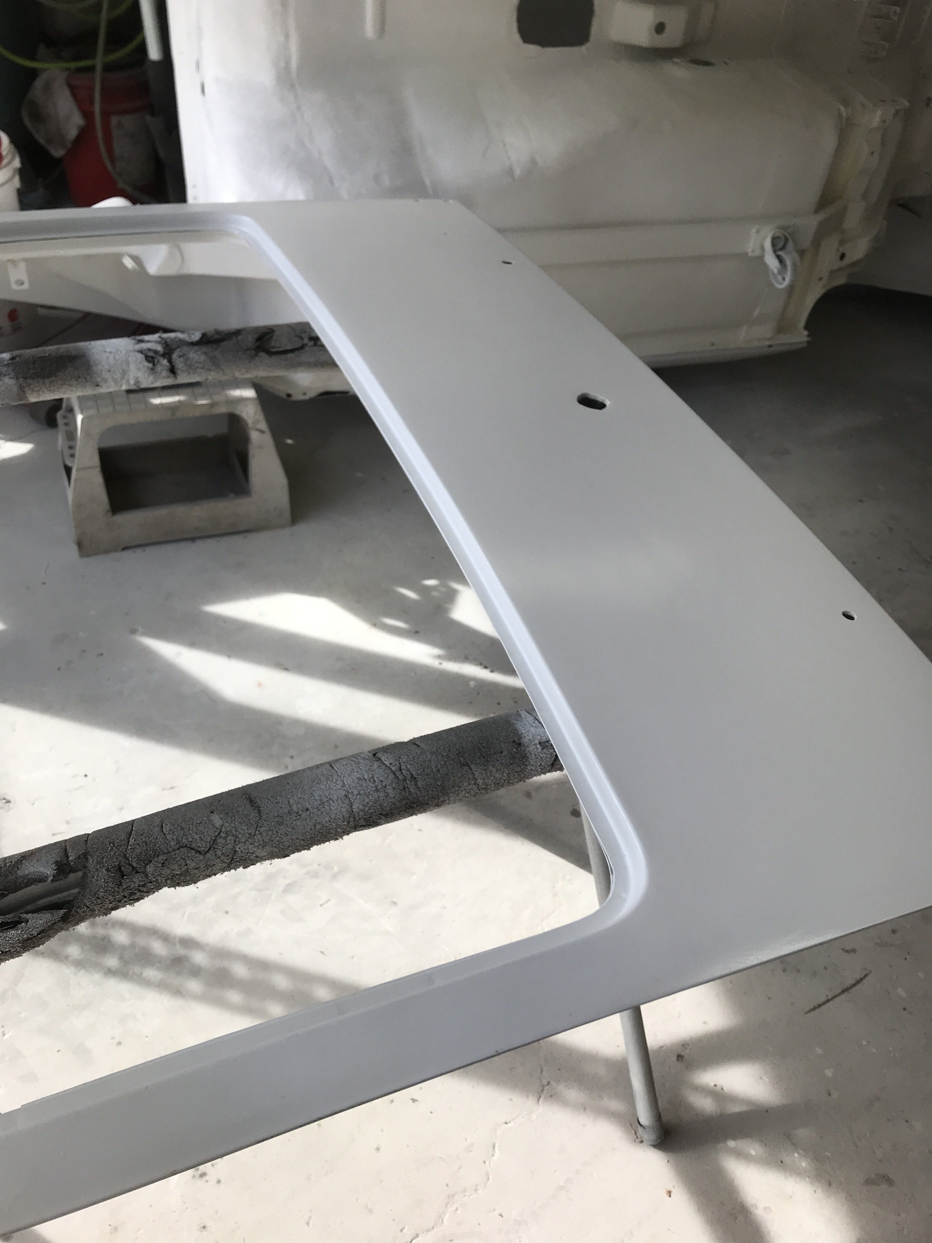
View of the front lower bumper panels primed by poly primer.
The bigger job was turned out to be the amber turn signal lens. Some of those tiny phillip screws(about 3mm) were rusted and had to be drilled
out.
Pic of broken lens mounting screws.
At first, I used gray JB WELD expoxy to repair those lens mounting plastic studs. Then upon putting the lens cover on the housing, the gray
epoxy created dark shallows in the lens. So I removed the gray epoxy and used
JB WELD Clear Epoxy was utilized to eliminate this problem.
The epoxy was dry to touch in a hour but waited till next day to drill and tap them.
Those amber studs were recreated by using plastic straws and masking tape to make a mold for the epoxy. The straws were slit to go around
the existing studs. Masking tape was applied tightly to seal and hold the mold while curing. Phillips 4-40 screws was found to be close enough to
replace the rusted ones.
The finished product
-
Now that the underside of the 240z is painted with single stage polyurethane paint. the car could be removed from the rotisserie.
I decided to construct a wooden dolly so the car could be move around the garage easily.
used 2"x 6" planks and 3/4" plywood sheets to construct the dolly.
The four metal 3" casters that were tack welded to the frame rails were reused and bolts to the 2" x 6" planks.
Two 1"x 3" wood strips were screwed to the top of the dolly to prevent the car from
slipping off the dolly. They run parallel outside of the frame rails.
The car was removed from the rotisserie and place on the dolly.
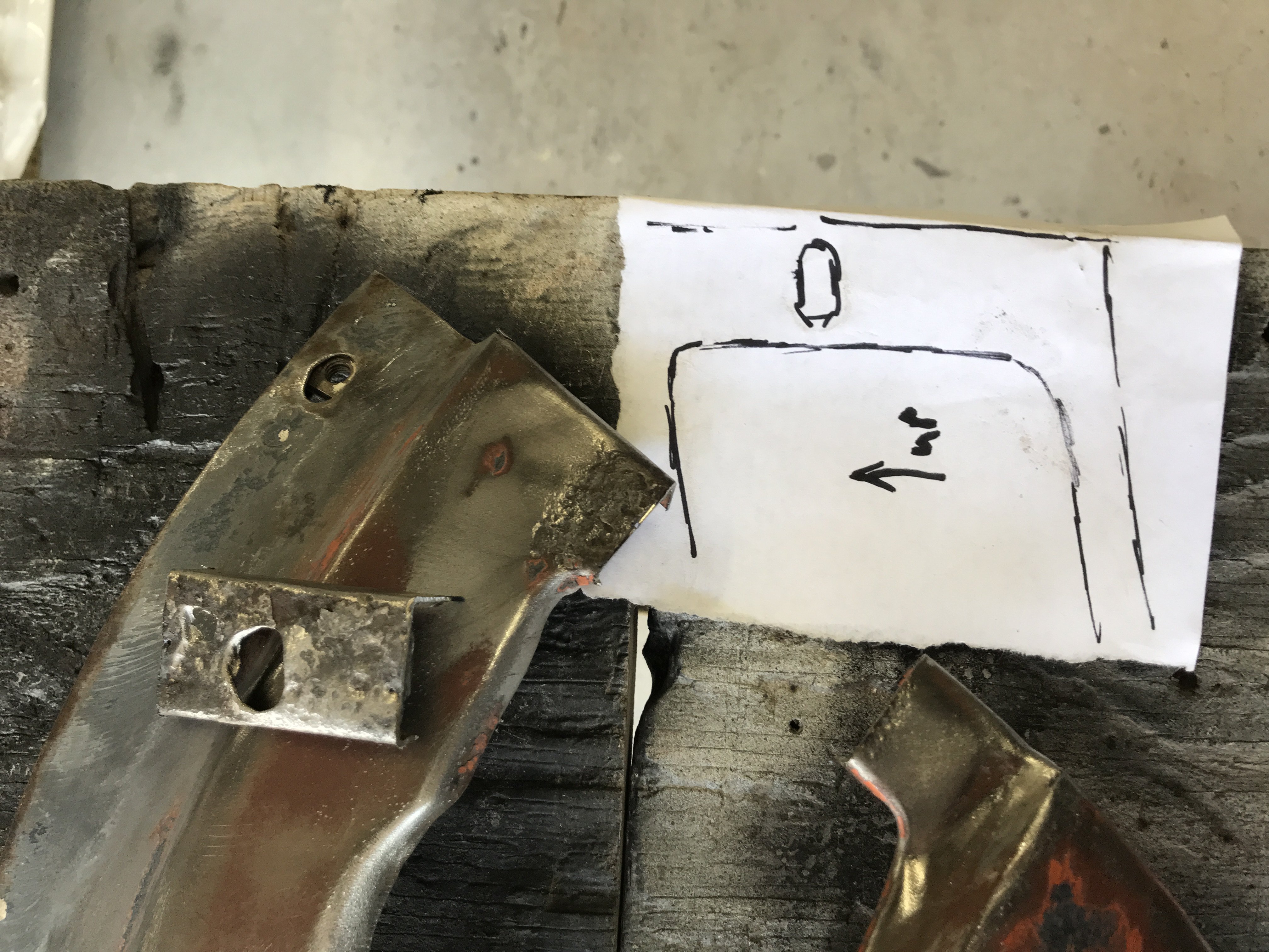
There were a few small parts that missed being epoxy primed so I started to work on them. The two front bumper panels were inspected.
Only the right side had corrosion problems.
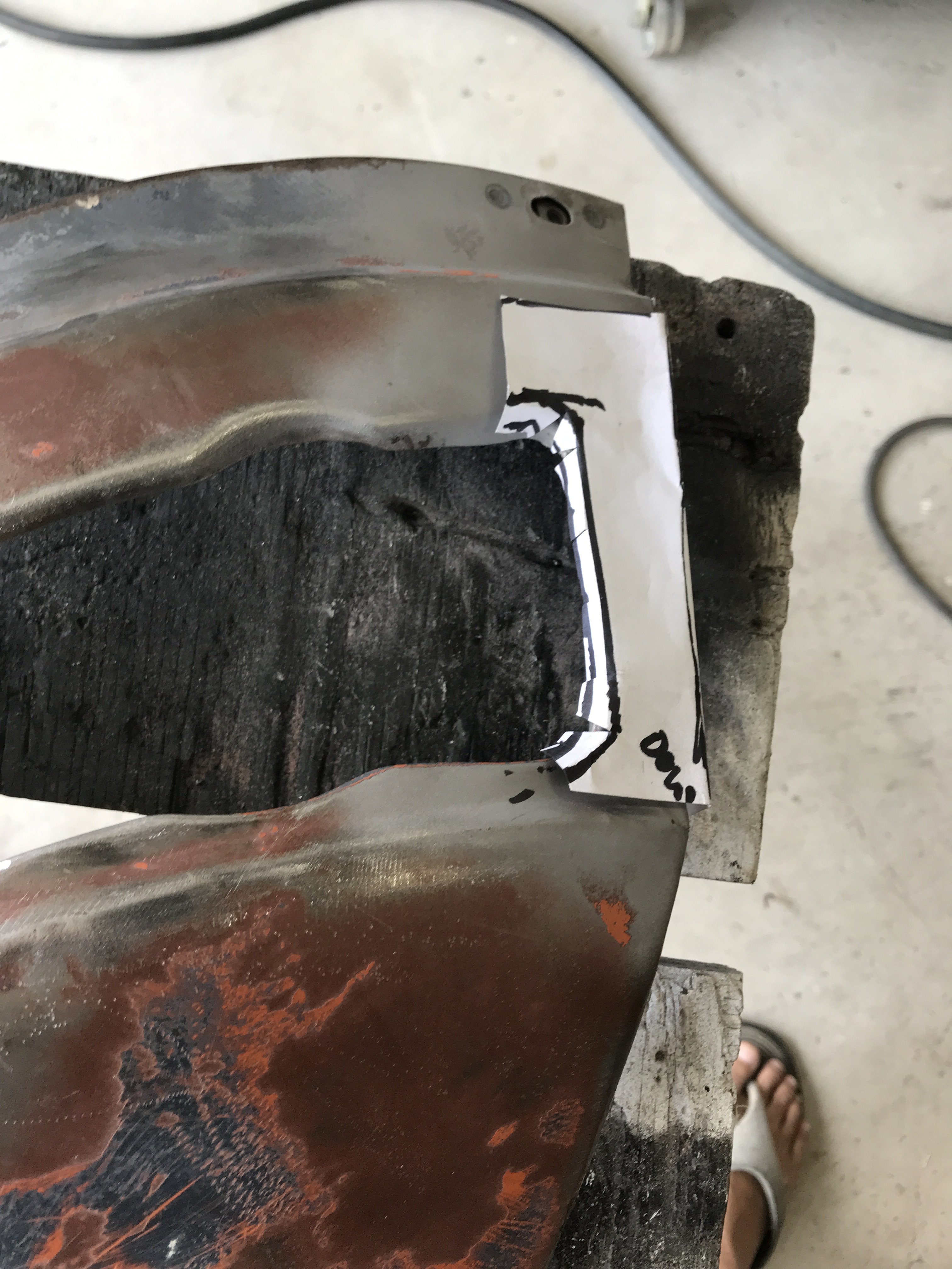
Right panel had two rusted out sections.
A paper template is created to the replacement section.
Another template was made to repair the other section of the bumper panel.
The template was traced on to make a sheet metal patch.
Inside view of the mig welds expoxied to
prevent corrosion.
Outside view of bumper panel epoxied
and will smooth over with body filler after epoxy primed.
-
Happy Holidays!! I just returned from my trip to Japan. On the second to the Last Day there. I managed to go to the Nissan Global Head Quarters
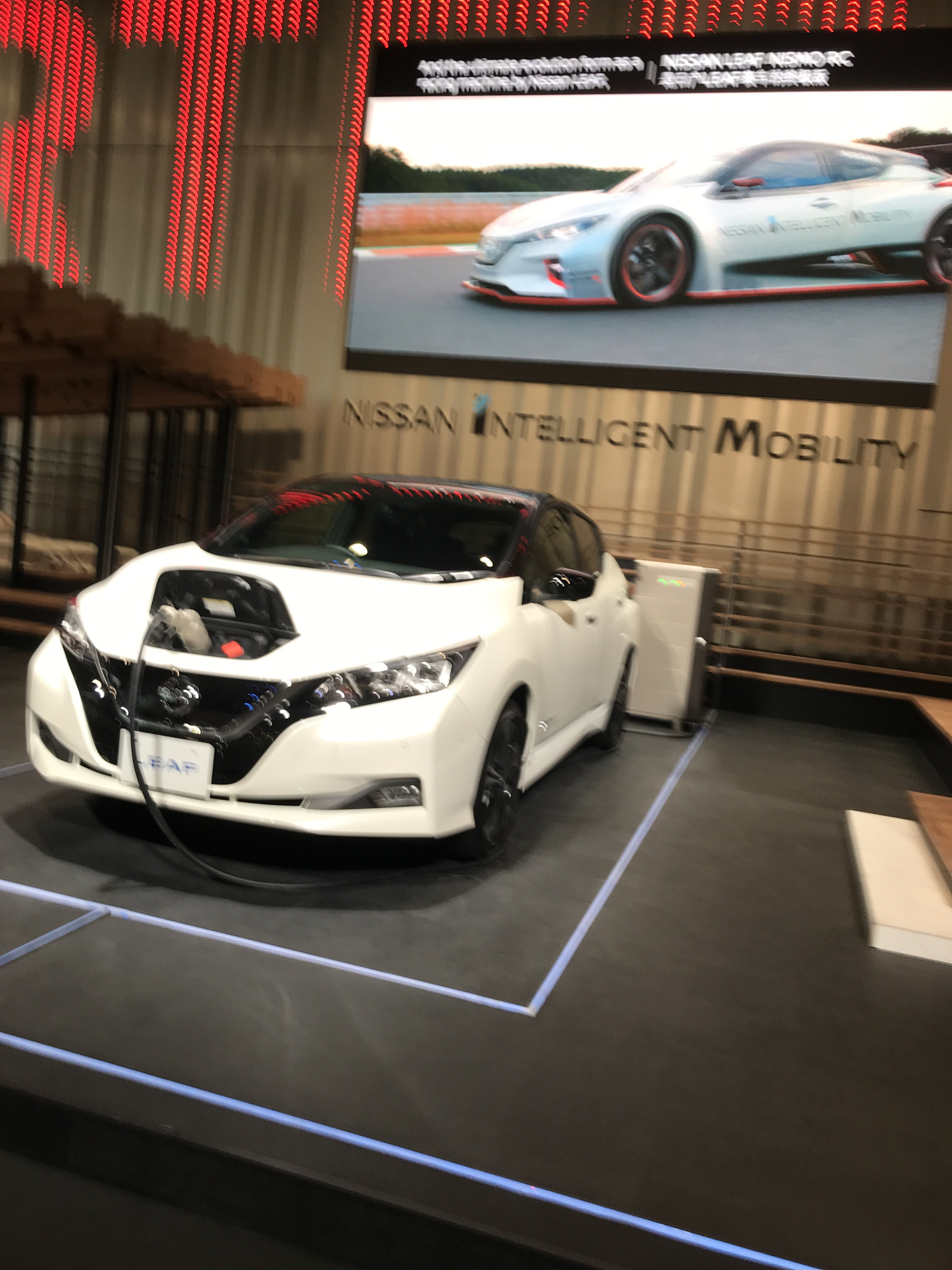
in Yokohama. It takes about a 40 minute train ride to get to Yokohama( located on the edge of Tokyo Bay). The car showroom is on the street level.
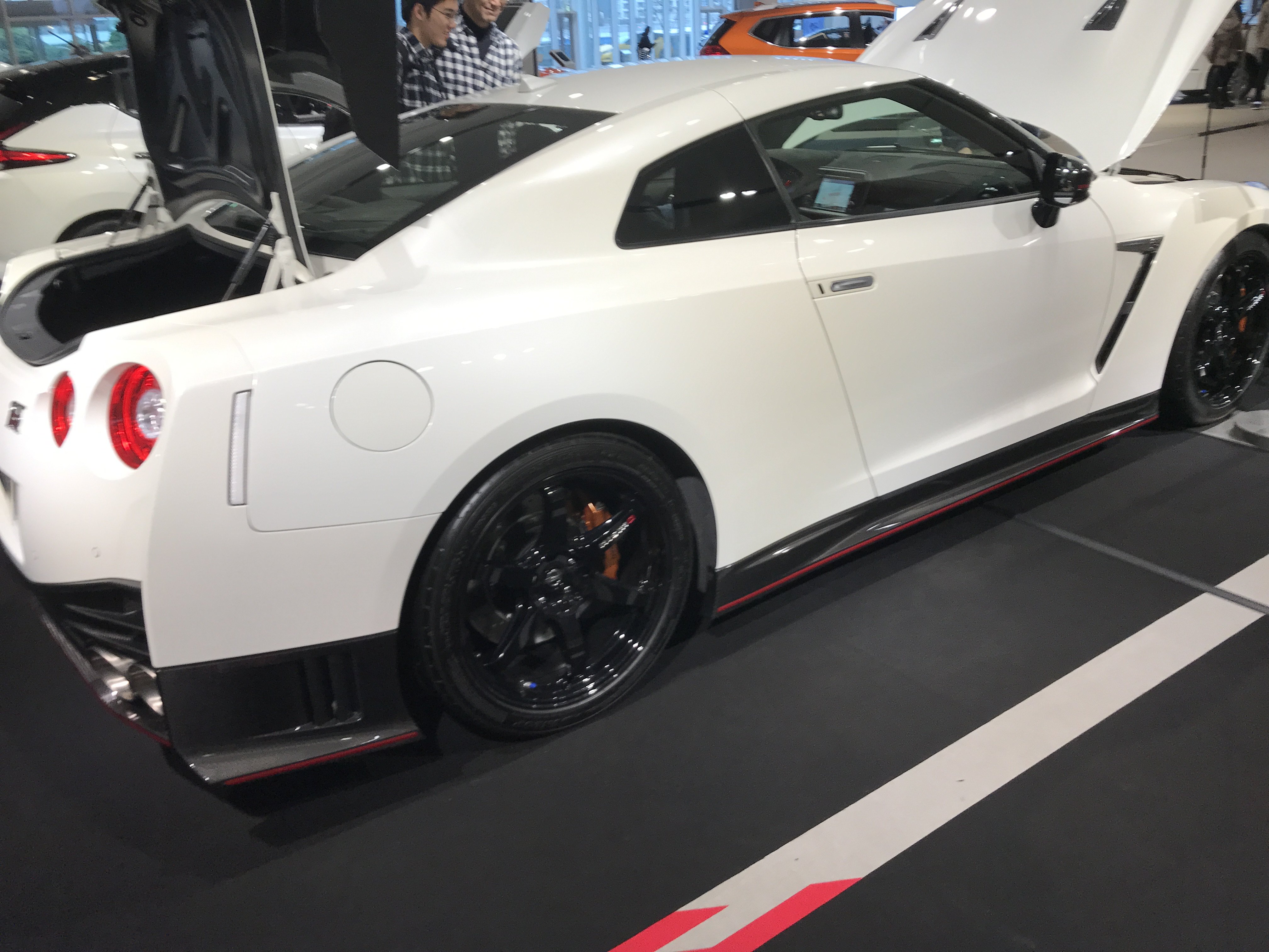
Although there was a lot of new model Nissans, I went straight to Skyline GT area. There was a White 2018 Skyline GT-R
Skyline GT-R on display.
20"Forgered alloy wheels and huge brakes
They also had a complete cut way GT-R undercarriage on display.
Twin cam 24 valve 3.8 Liter twin turbo engine rated at 600HP and 481 ft lbs torque.
5 speed automatic transmission with all wheel drive
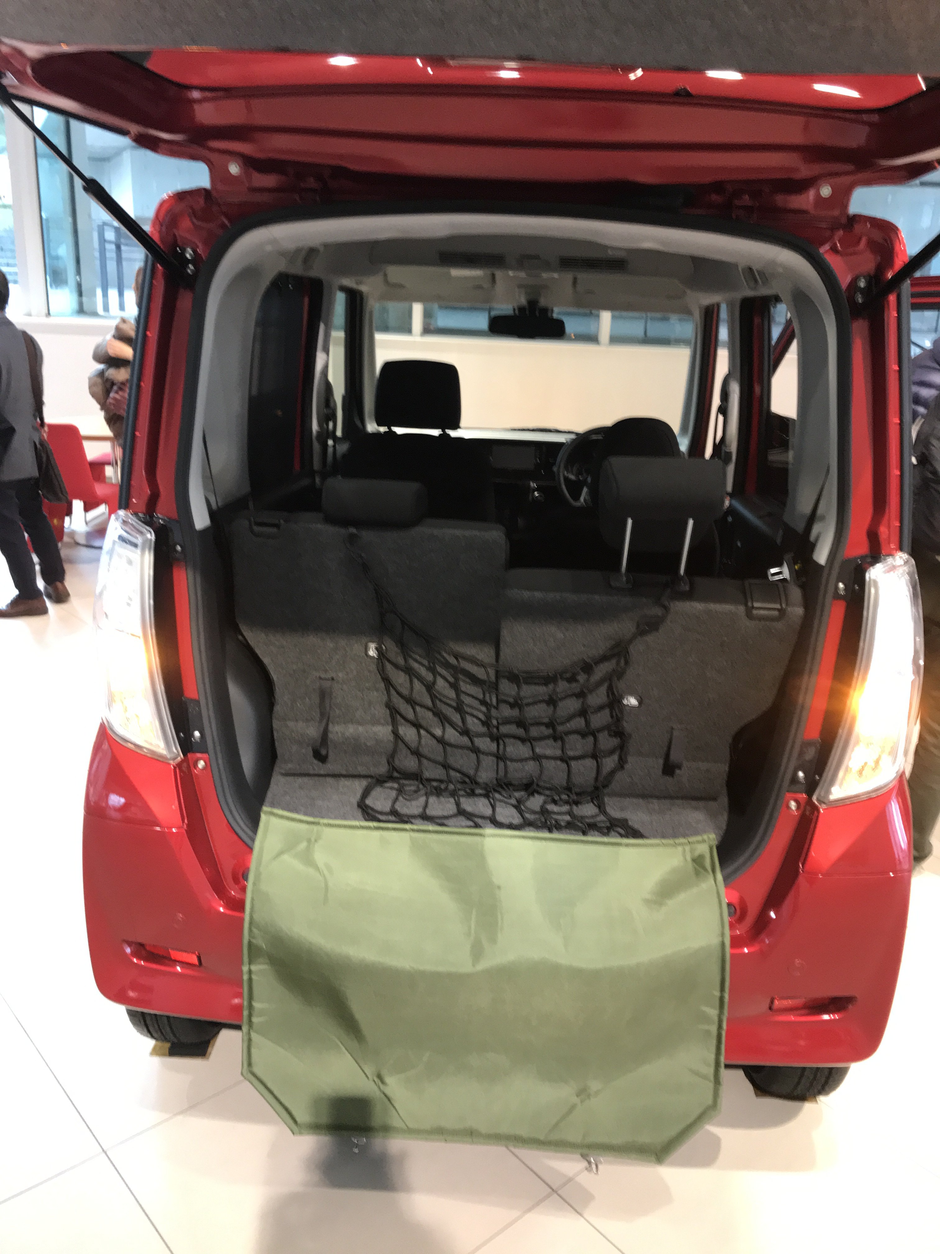
This is a cute Nissan mini van-not for Export though.
They had a NISMO-High Performance section there too. Mostly t-shirts and promotional stuff but I found out there was a
NISMO SERVICE CENTER near by. They have race cars on display there and do special work on customer cars too. It was only 15
minutes by taxi but I already had plans so could not make this time but will next time I am in Tokyo.
-
Sorry for not posting in for a while. I was busy decorating my house for Christmas.
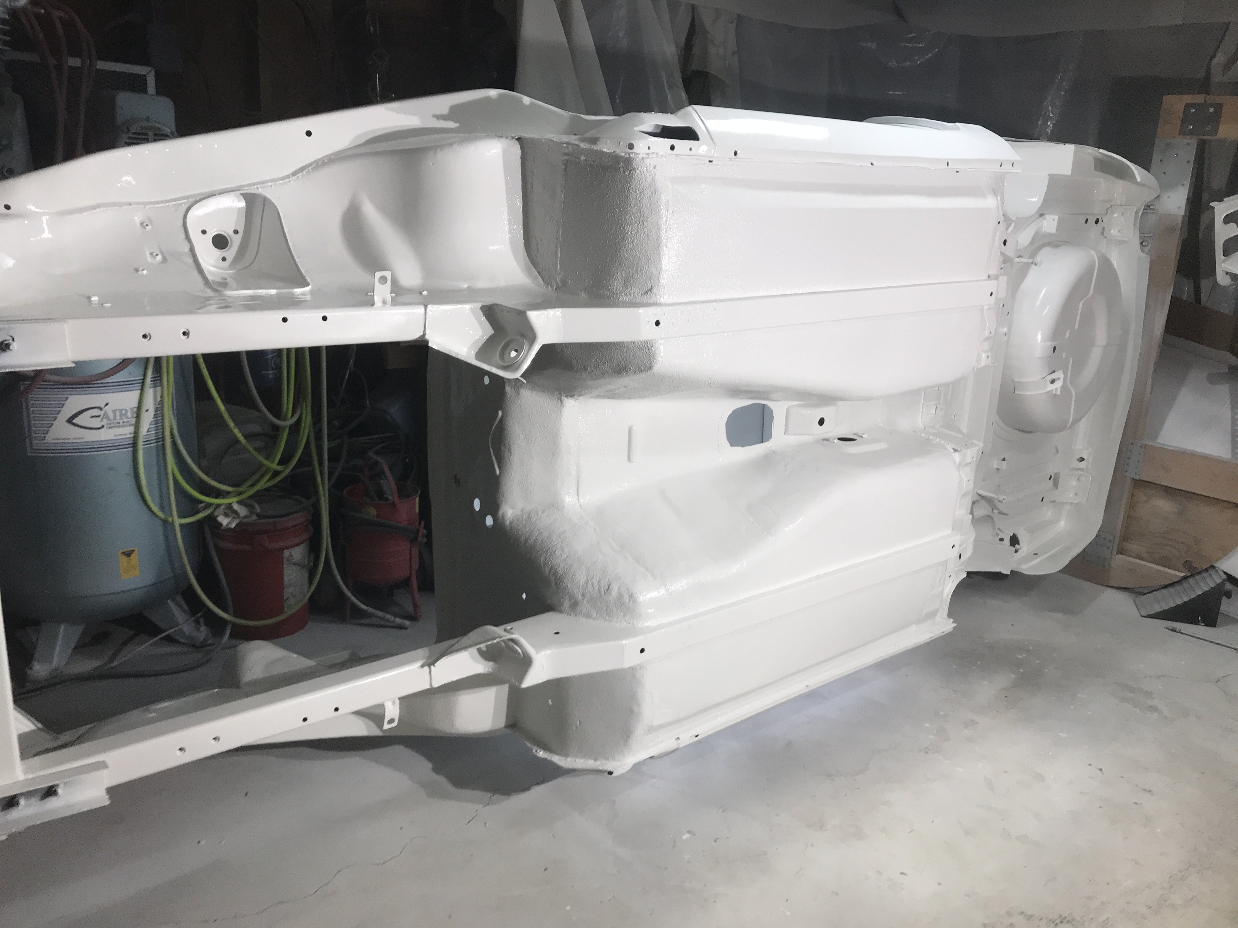
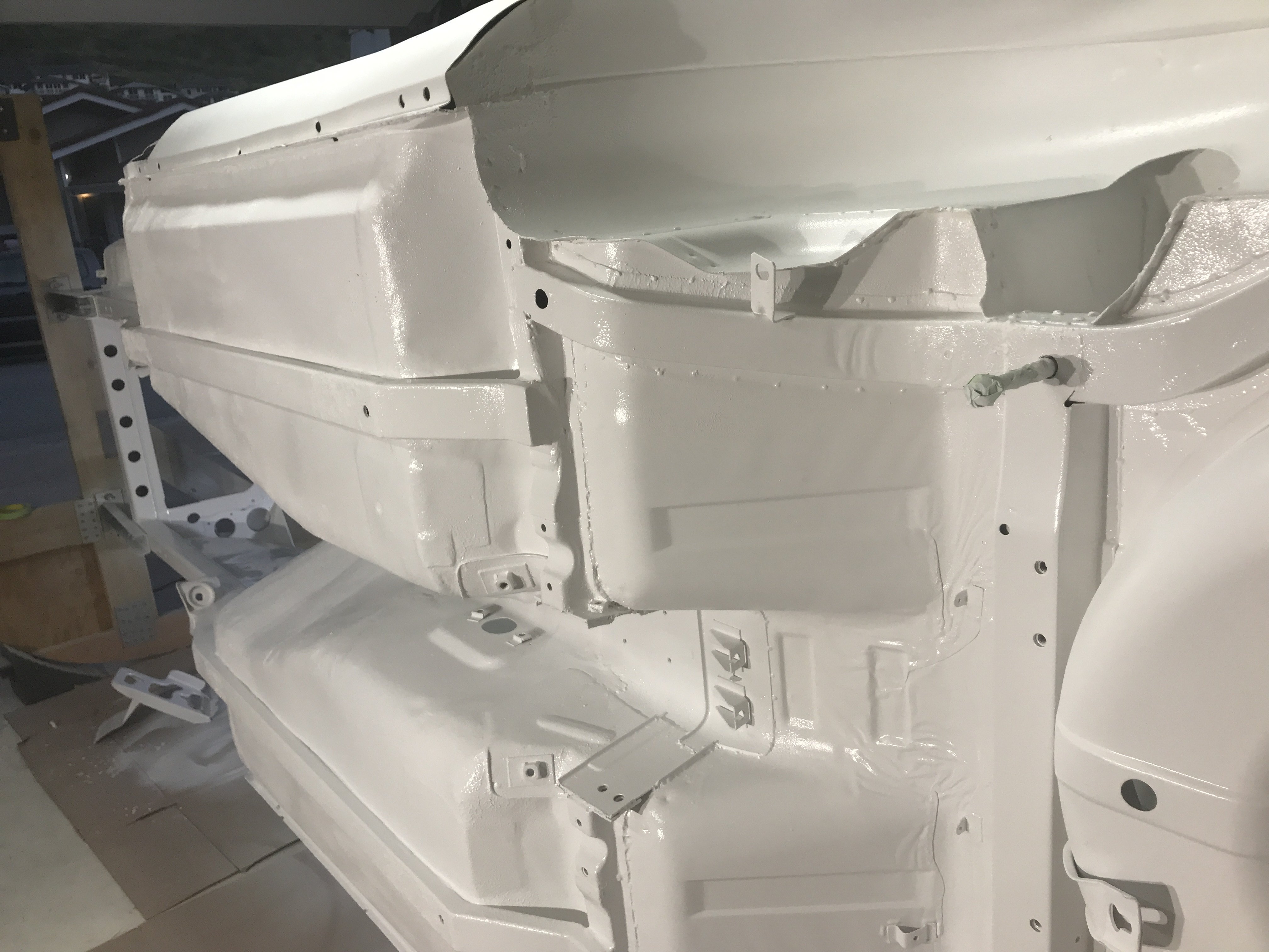
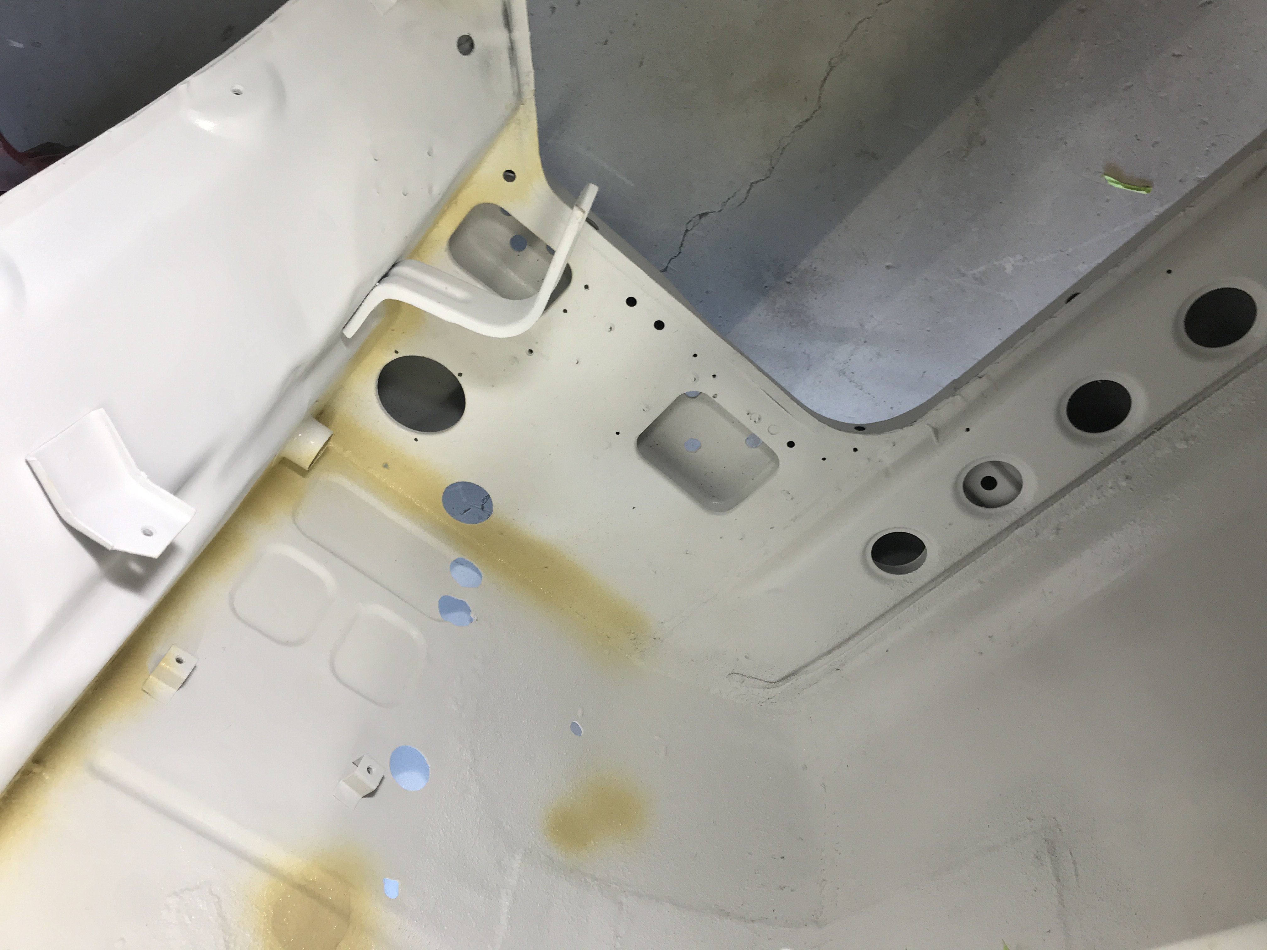
Painted the bottom side and inside of the interior of the car.
View of bottom of the front frame
The bottom view of the floor pan and frame connectors.
The rear of frame and bottom side of hatch area
The interior floor and firewall was painted then the bottom side of the roof was painted too.
The engine compartment and core support was covered with two coats of single stage polyurethane paint.
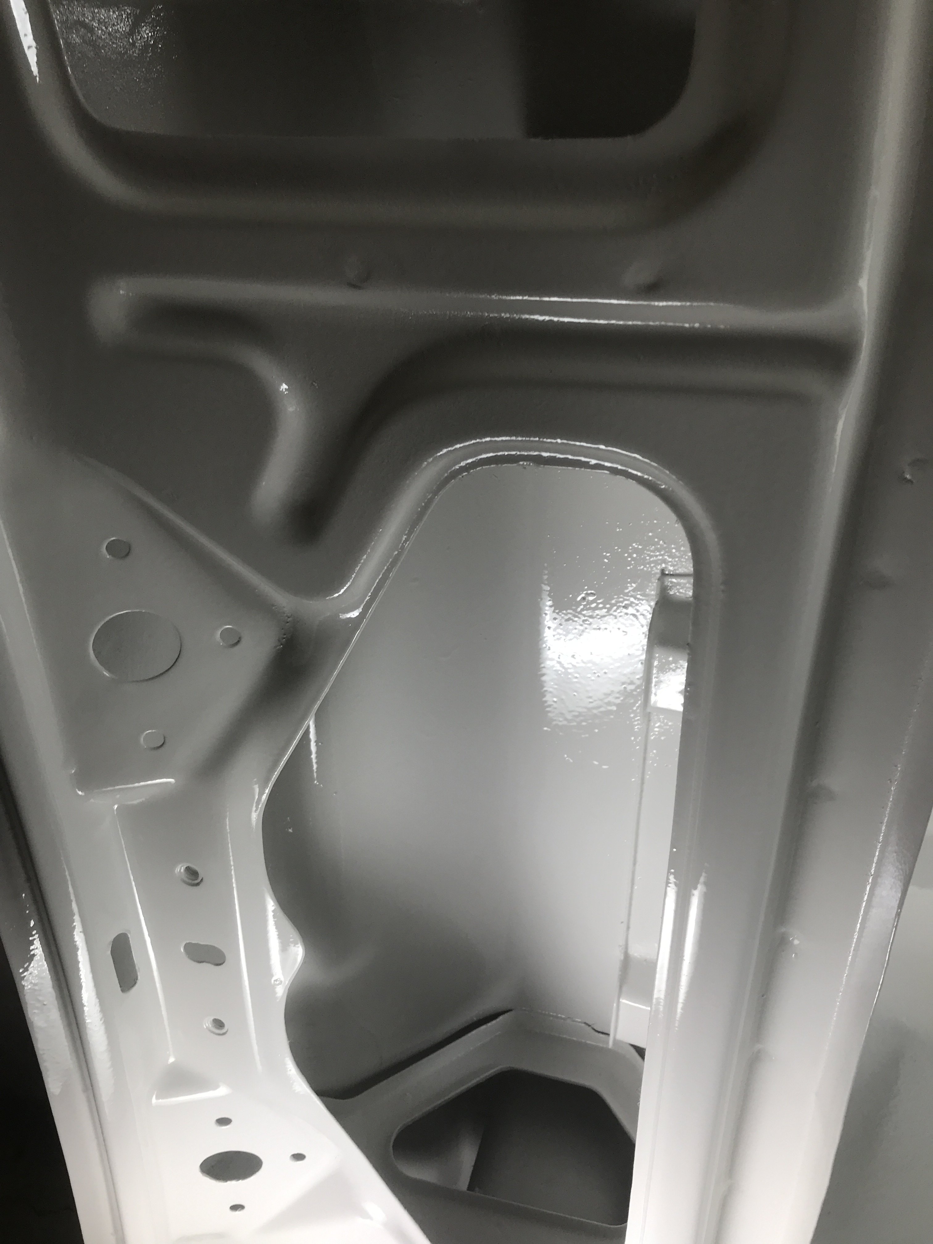
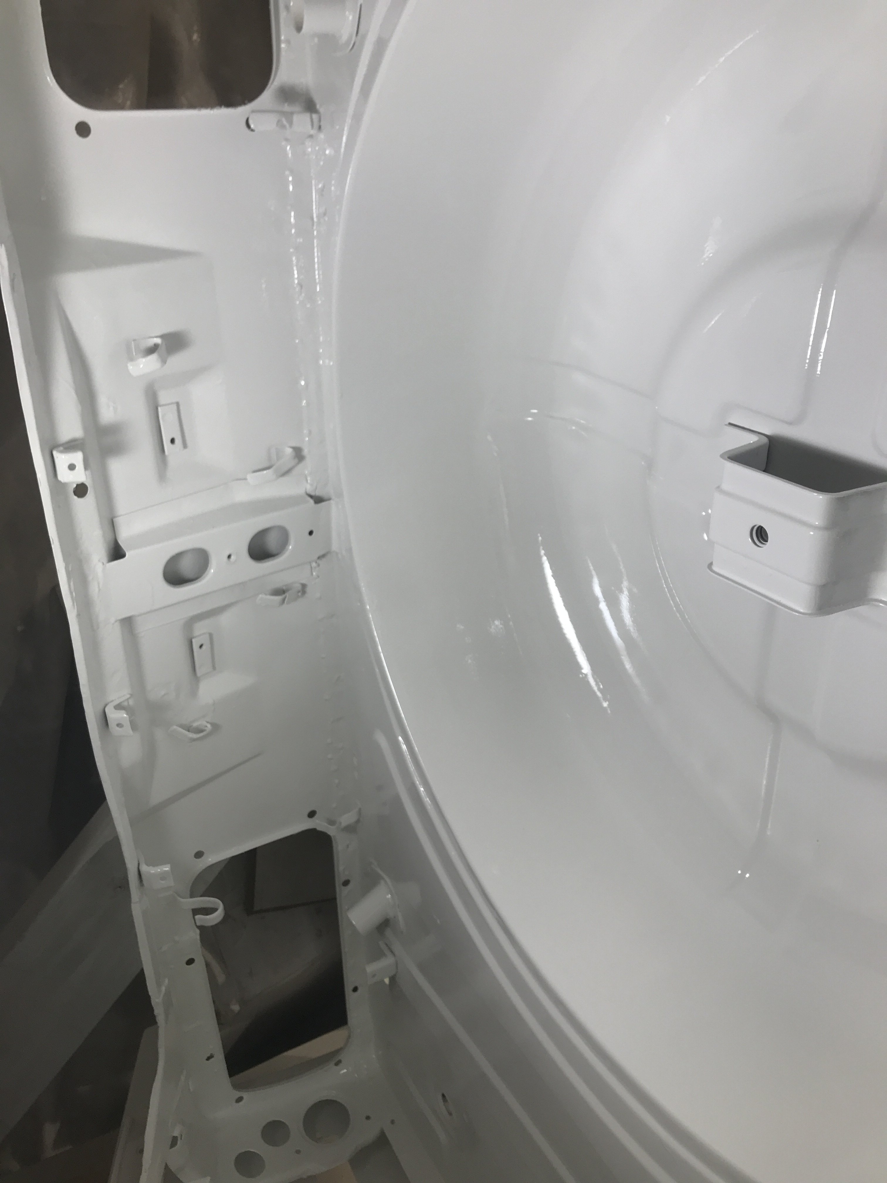
View inside of the cowl area
The spare tire well
Only the interior of both doors, the hatch and front valance pan still have to be painted with single stage Polyurethane paint. The
rest of the exterior parts of the car will be painted with polyurethane base color then clear coated.
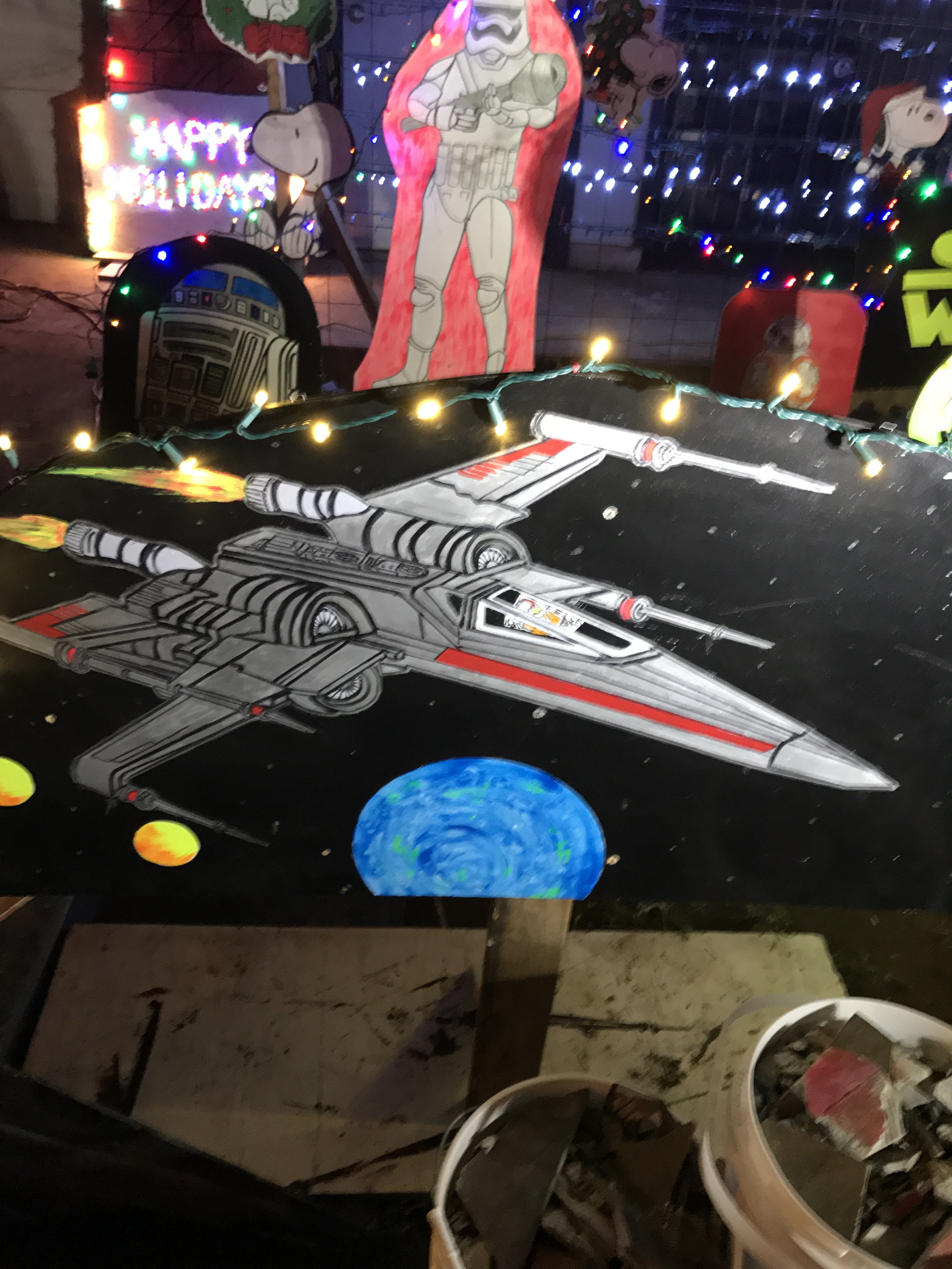
House Christmas decorations
Snoopy and Star Wars theme
-
https://www.cyriousgarageworks.com/2017/09/06/rocket-bunny-240z-a-modern-classic/4/ This video shows a garage restoring a 240z and
using a Rocket Bunny Body Kit. It has a very detailed and well done metal work. I also am deciding on what flares or body kit to use on my Z.
Going to Japan for vacation so I plan to check if they have anything new over there. The first weekend of December there is a two day car show in
Yokohama but I will miss it. There are a lot of Chinese copy cat Rocket Bunny kits on the market so beware. Japan has better fitting flares and
body kits but are usually the most expensive too.
Toolman
-
https://www.youtube.com/watch?v=OVnxPL2oeQE&t=129s Found this video that goes in the mind of Kyle Kuhnhausen-Winner of 2018 SEMA SHOW Young Gun Builder. This 71 Datsun was made in his two car garage in period of 5 years.
Toolman
-
fluidmotion, , I am sorry, I forgot to answer your other question. I removed all of the factory seam sealer from my car. The old factory seal sealer was cracking and peeling off. The new poly seam sealer are much better than the old one(more flexible and resilient). For an even more through job, I sprayed seam sealer over areas prone to corrosion. Like
the battery area where battery acid and flumes cause rapid corrosion on the metal. Then top coating the whole car(interior and exterior) with polyurethane paint(aircraft paint)which should last for 10+ years.
-
fluidmotion, I used SEM PRODUCTS 1K sprayable seam sealer. It is a modified high performamce polmar silane seam sealer.
It is OEM approved and used for Chrysler as a undercoating. .It is flexible and non sagging. Also, this sealer can be painted immediately
after application. It comes in white, beige, gray and black colors. Amazon sells it for about $15 to $20. There is newer sprayable seam sealer
2K seam sealer( two part). Both sealers require a special spray gun to apply though.
-
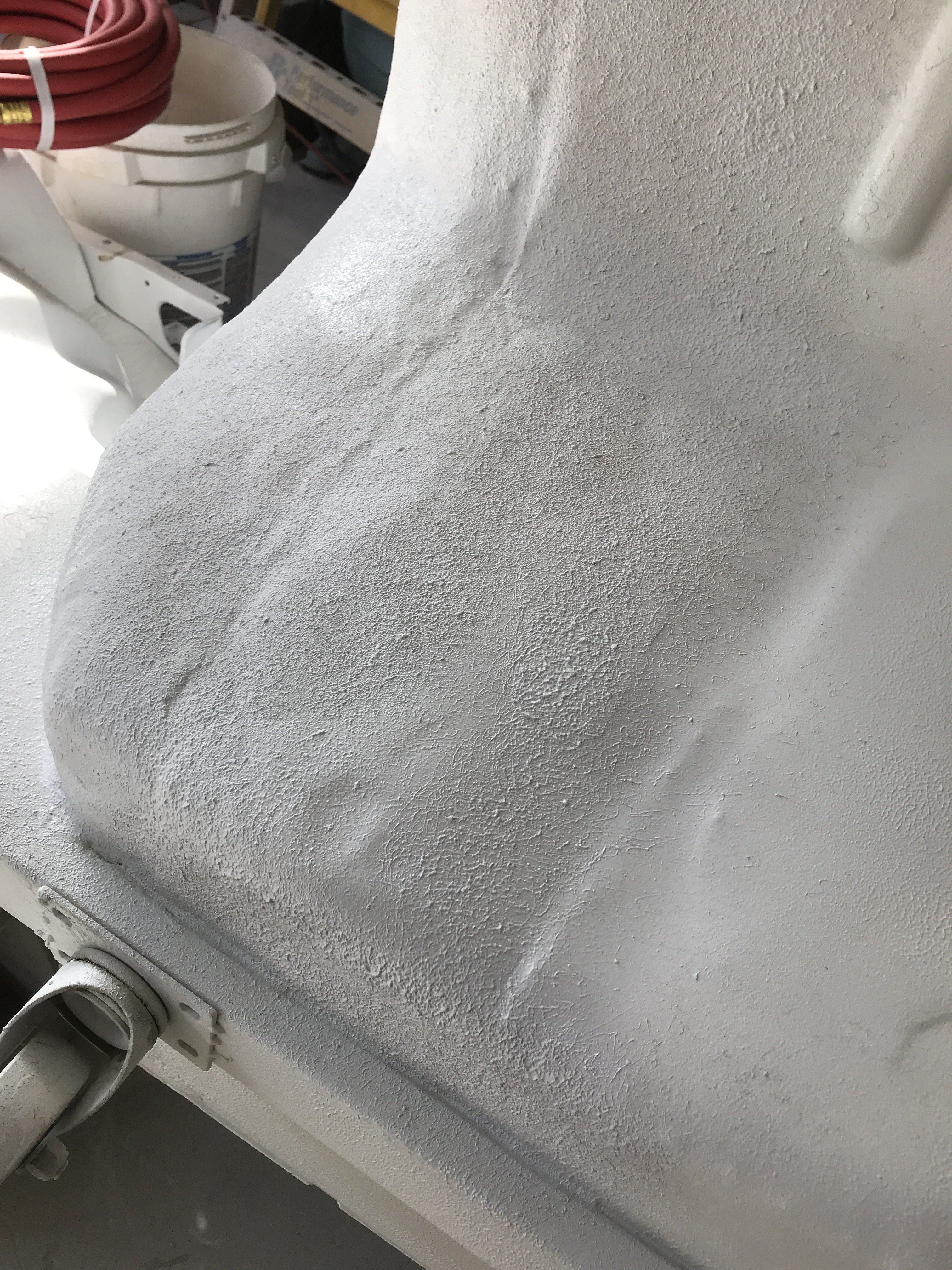
Finally got four more tubes of SEM PRODUCTS sprayable seam sealer. So now I could add two more coats of sealer on the bottom side of the passenger compartment. This would provide additional protection against heat and noise in this area.
Note- the four casters for moving the car around the garage were removed. Once I finished painting the bottom of the car. the car will be removed from the rotisserie and place on jack stands.
Save the casters to make HD dolly or another project
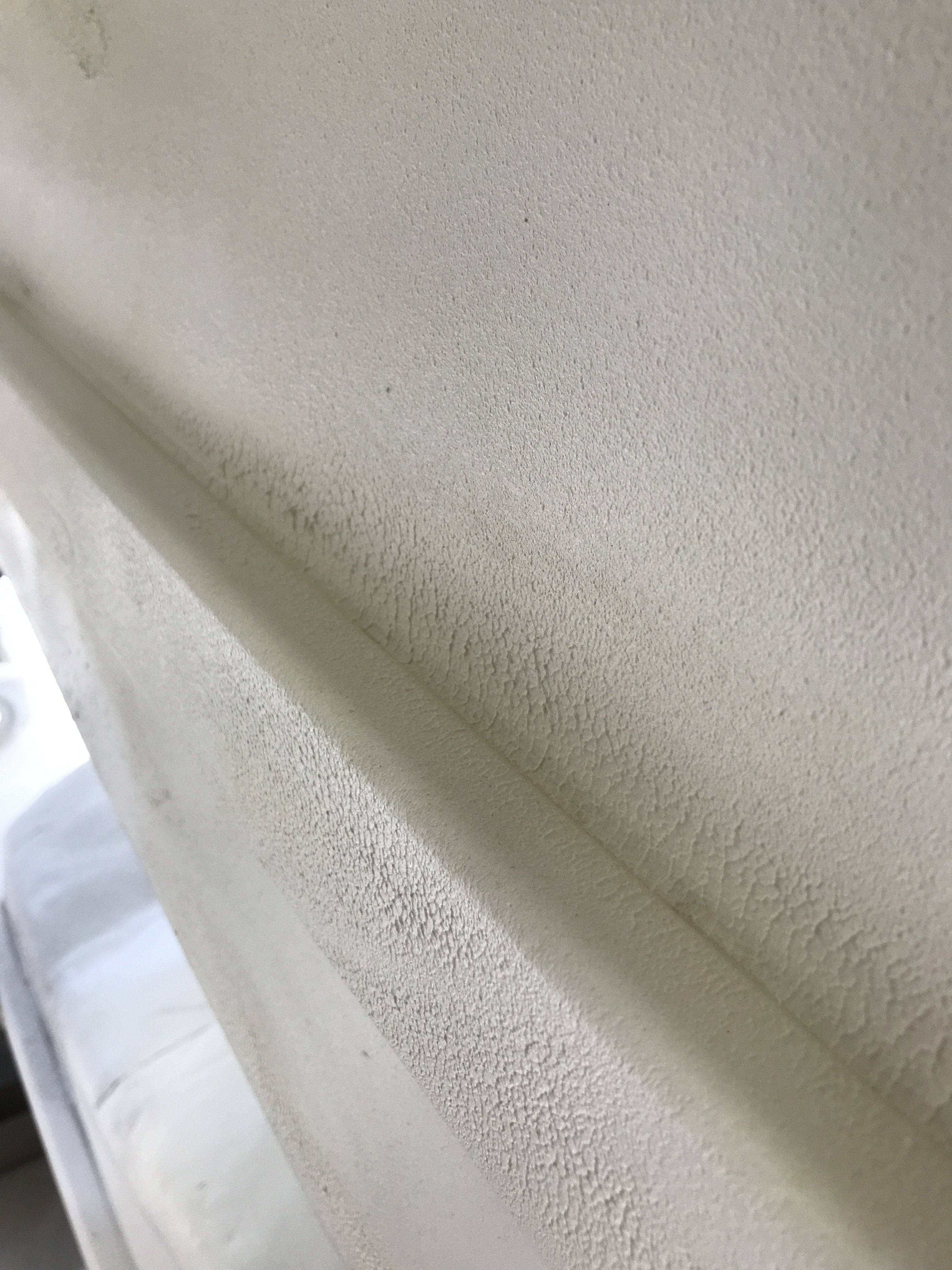
Closeup up view of the seam sealer texture
Seam sealer was sprayed on additional areas in the interior of the car.
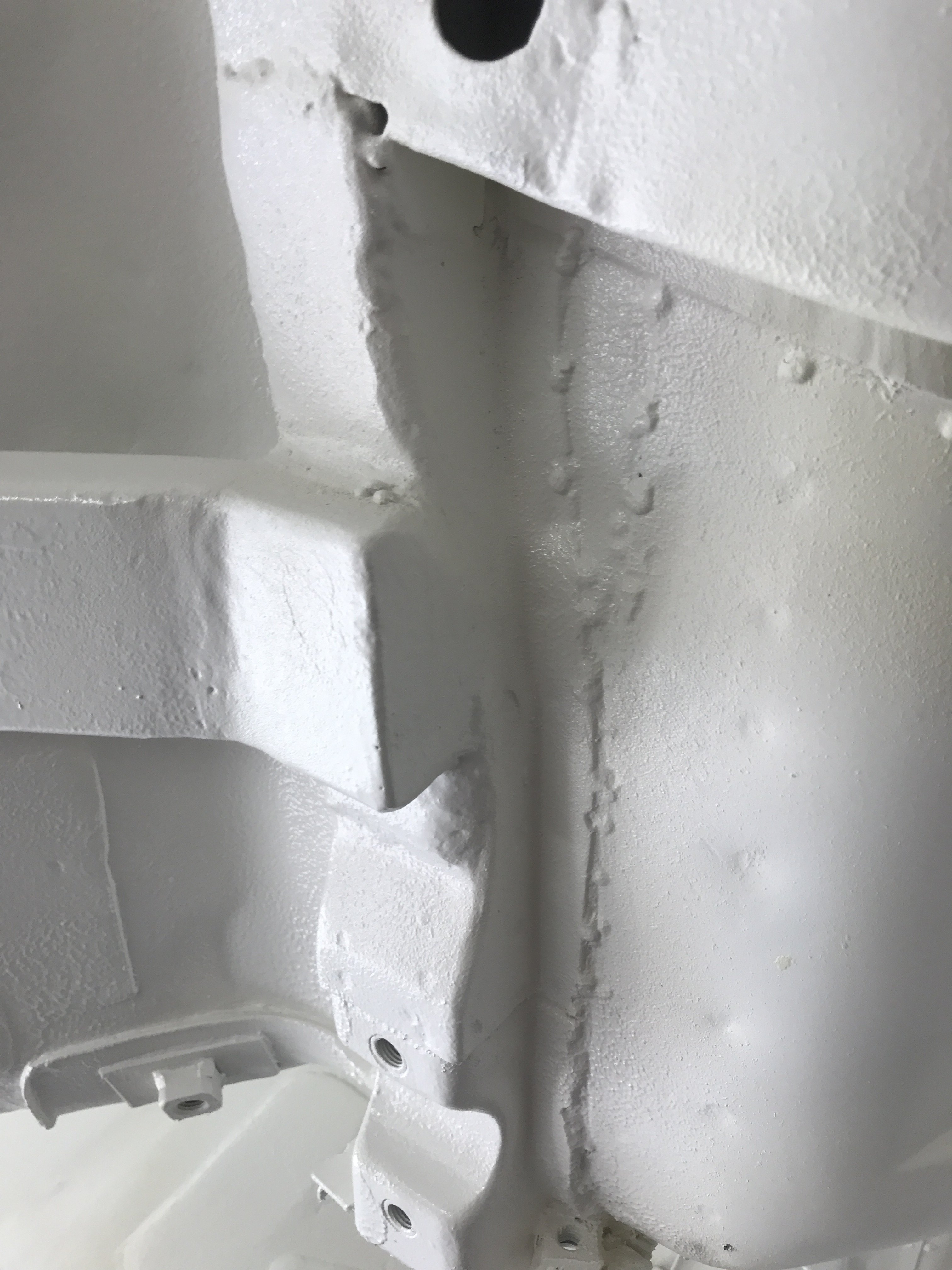
The rear underbelly also receive additional coats of seam sealer.
Rear bottom( spare tire well)
Rear frame area
another closeup view of seam sealer
Trans tunnel and frame rails recoated
Next step will spray painting the whole bottom and engine compartment with Sherwin Williams single stage polyurethane paint.
-
As I have not recovered fully from the lower back injury, I doing light work on my car till I recover. To prevent or at least delay any
future corrosion, I am making rust proofing access holes. But, first the front end of the car, water drainage holes were added.
On the left front fender reinforcement section, four 1/4" holes were drilled in the lower edge to provide additional drainage.
The interior of this reinforcement and air inlet tube will also be rust proofed after painting.
The right side had similar work done.
This picture gives a overall view of the left side rocker panel drilled for rust proofing access holes.
The left front rocker panel had three 1/2" rust proofing holes drilled.
The large hole was the area where corrosion was cut out. As this area is a major rust area, the interior will probably be brushed painted with a rust encapsulating paint then welded shut and rust proofed.
The lower rear rocker panel had two 1/2" rust proofing holes drilled. The inside of this area will also be brushed painted with a rust encapsulating paint then rust proofed.
Without these access holes, you would not be able to get rust proofing into those rust prone areas of the car.
Right frame hole shows what the 1/2"rust proofing plug looks like installed. Both connecting frame rails have four rust proofing holes each. All of the 1/2" rustproofing holes will be plugged after rust proofed.
-
240zJJR, You did a nice job on bracing. If you are worried about the present frame condition, you can take frame measurements with your car
on the rotisserie. If you have access to the auto body shop, borrow a Tram gauge( for frame measurements) and frame gauges( these 3 gauges
will show if your frame in alignment (centerline and height). If the major part of your frame is crooked. it will next to impossible to repair after a full
roll cage is installed. The frame machine will tear the vehicle apart. A good frame man should be able check the vehicle in less than an hour.
The other option( if the frame is real bad) is build a entire tube chassis and mount the 240Z body shell on it. By the way, are you building a street car
or a full race car?
Toolman
-
On 11/6/2018 at 5:30 PM, toolman said:23 hours ago, 240zJJR said:
I was at Sema as well. Such an amazing event. This was my very first time as well. I missed Kyles car as they moved it for the final judging. Tyler Powel Z06 was awesome to see, really great guy. I also spoke with Chris from B is for build.... awesome dude as well.
I have been following your thread and you have made some amazing progress.
Question for you, I am following the same process you are and making a whole new frame for my 240Z hellcat swap. The way you installed the frame rails under the car (NOT THE ENGINE) i noticed you cut the floors out and braced the car. I will be doing the same (already braced). Did you have any flex at all and is your car squared up properly? Any words of wisdom or advice before i start cutting this weekend.
I started my own thread showing the progress.
Thanks so much Jeff
SleeperZ, Thanks, Keep checking this post as I am still adding more pics and text of the Show.
240zJJR, First, Just check the squareness of interior?engine compartment before welding bracing in. Usually you really don't know if the vehicle was in a previous accident or not. In my case, I measured from the seat belt mounting hole crosswise to the lower door
hinge mounting hole. Perform the same on the other side. Your two measurements shouldn't vary more than 1/8" to 3/16". After that.I made
3/16" plate to mount 1" X 1" steel tubing in a crossing diagonal pattern. You can also weld four 1" tubing from side to side and front to back if
you wish too. I use this method for the engine compartment as I was removing the frame rails also. You should measure frame length( front
to back) especially when building a new front frame. And, of coarse, use a bubble level for front to back and side to side checks. One thing
a lot of people forget the vehicle must be level to begin with(before any work is done). I used 1/8" steel shims( or bigger if needed) tack welded
to the top of the jack stands to raise or lower the car. Place bubble level on the rocker panels to check. I hope this helps. There are a lot of
people on this forum that will also help you.
Toolman
I twisted my back so haven't be able to work on my car for now.
-
https://www.youtube.com/watch?v=PCPfHHMaQ64
I knew it was a matter of time before someone try to put a Hell Cat motor into a 240Z. I think they might have to cut the hood or cut the firewall
set the motor more back. Interesting, anyway. https://www.youtube.com/watch?v=GR05Je02rUY
-
SleeperZ, Thanks, Keep checking this post as I am still adding more pics and text of the Show.
https://www.youtube.com/watch?v=_9fN7ntWKAY&t=126s Check this 2017 Nissan GTR out!!
https://www.youtube.com/watch?v=e4TqX-eWkWM&t=85s 2018 Sema Show Young Guns Winner
https://www.youtube.com/watch?v=DU656s-qti0 overall view of Sema Show
https://www.youtube.com/watch?v=B0q-fwwS9Vs video of 58 Chevy with metal engraving in spray booth
Farm Truck from STREET OUTLAWS was there.
-
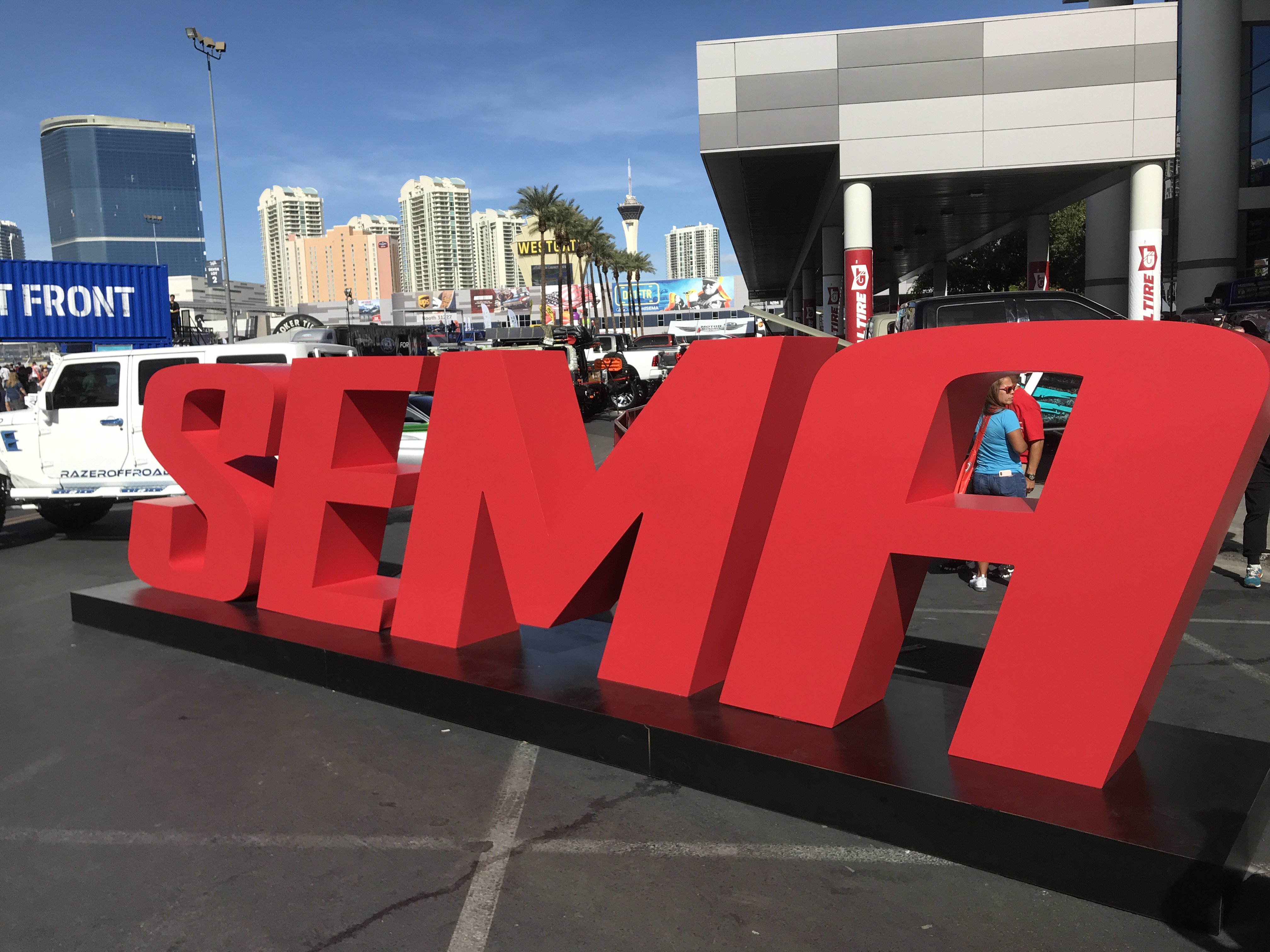
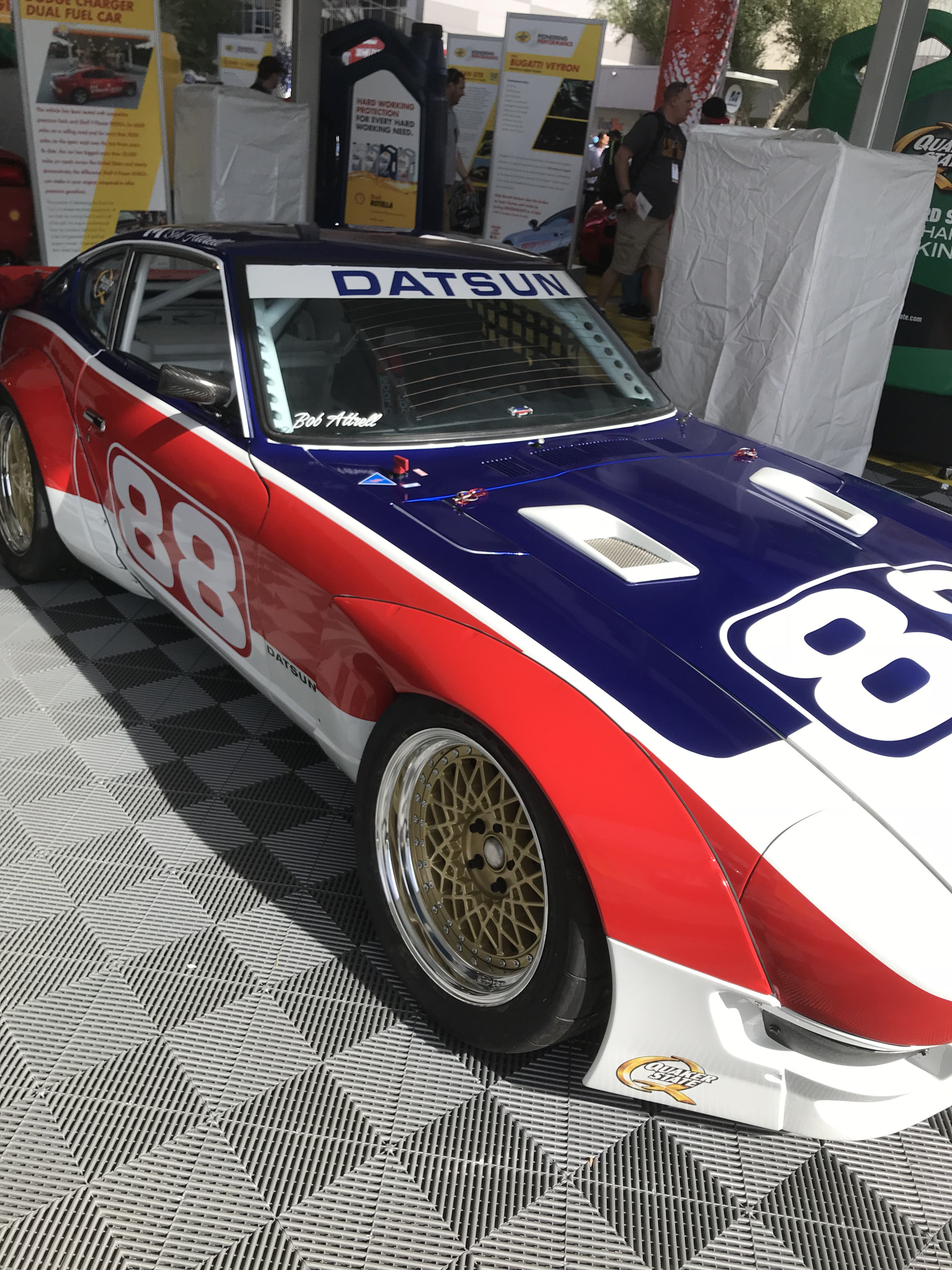
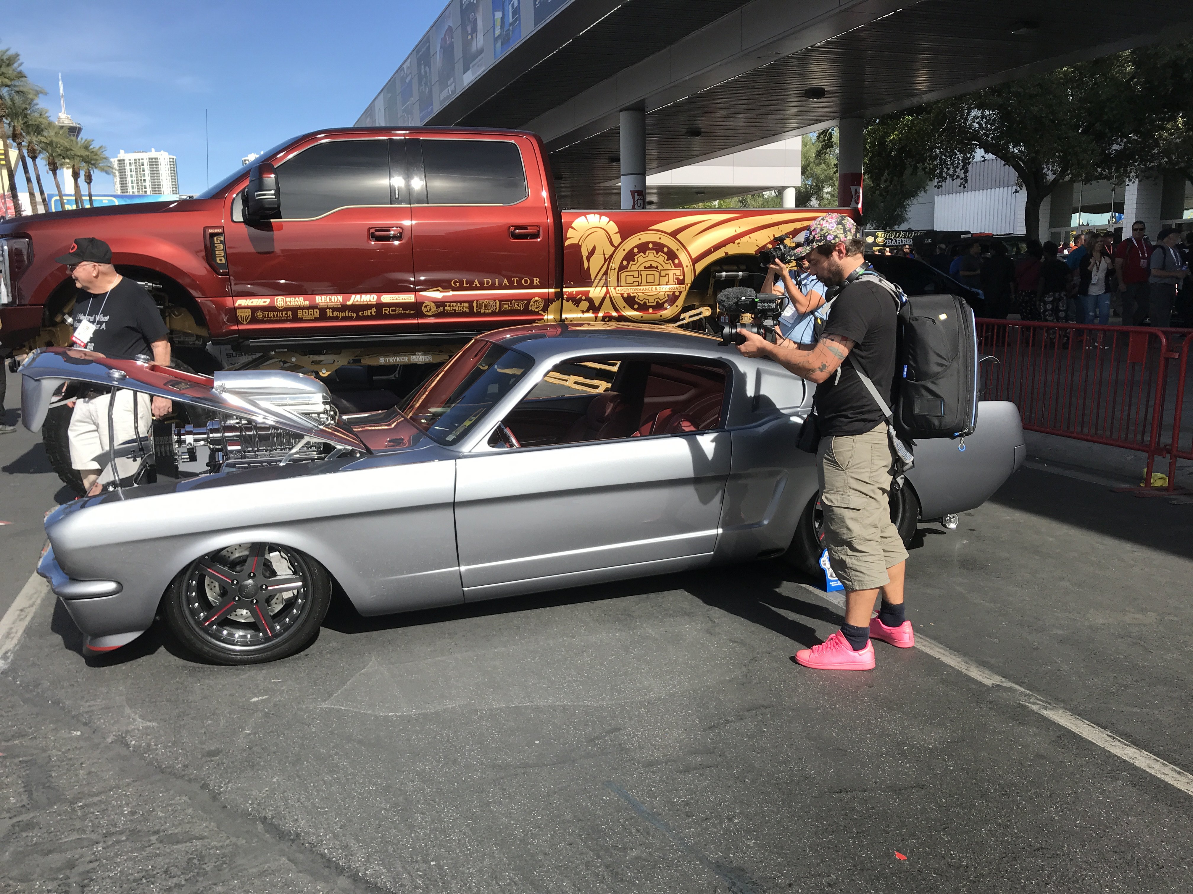
There were hundreds of exhibitors and attendance was probably more than 170,000. I will attempt to give you guys a small sampling of the show at this show.
The winner of the Young Gun Builders of SEMA Show was Kyle Kunhausen. He spent 5 years building this early 240z in his home two car garage in Oregon. Go to https/www.youtube/watch?v=pCfLQHZgnCM&t=49s
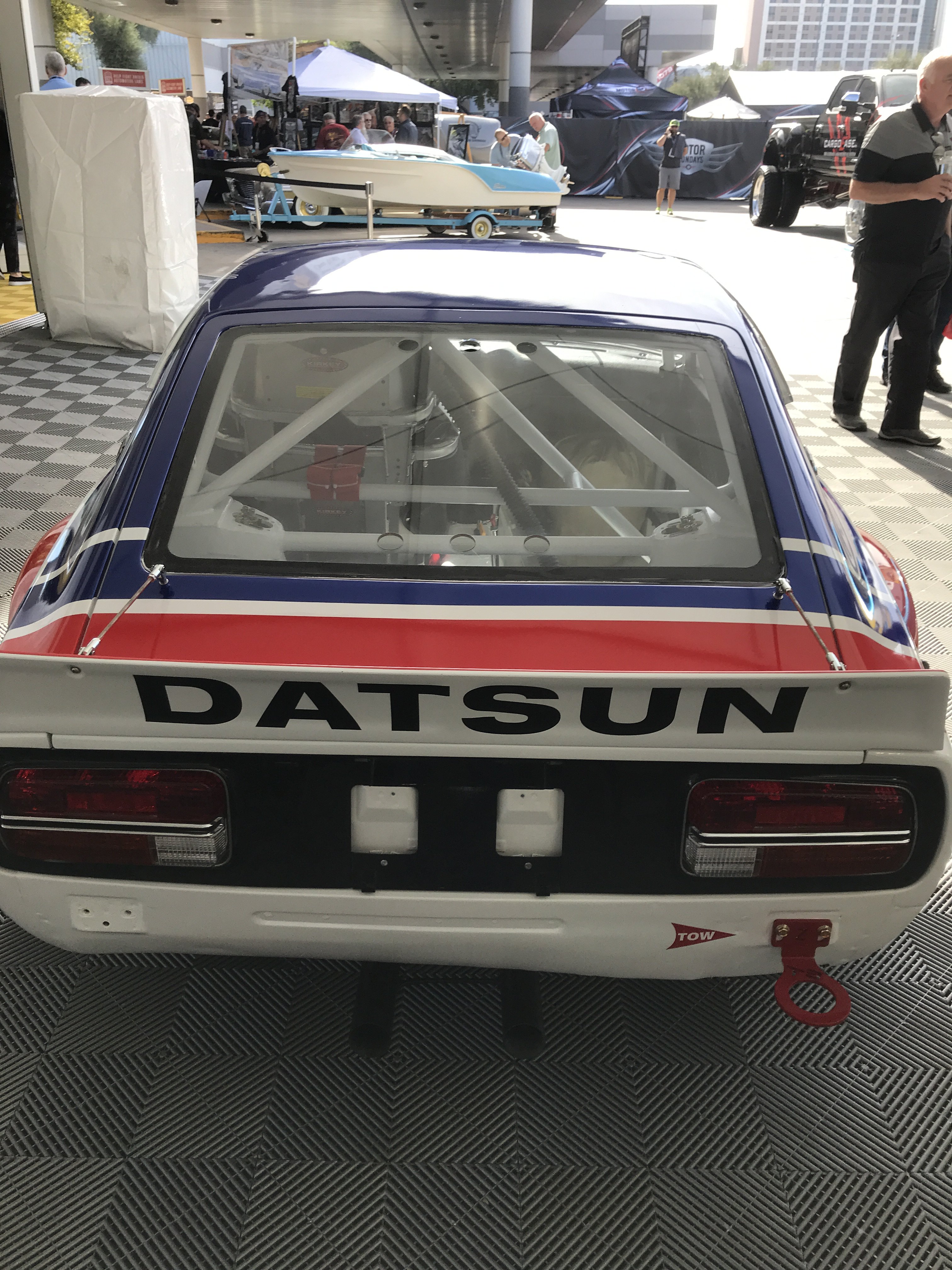
Bob Sharp 240Z race car
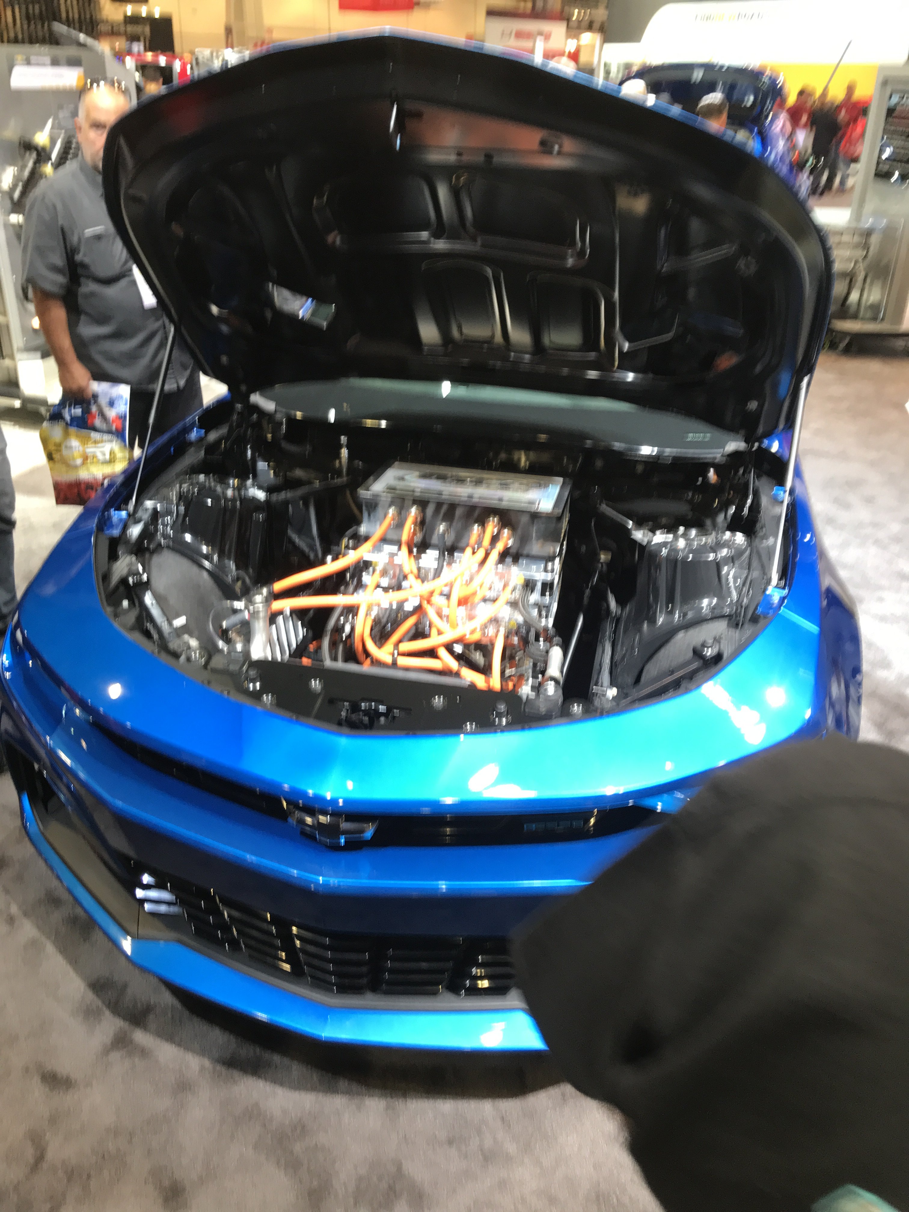
General Motors had an ALL Electric motor powered Camaro on display. It provides 800volt batteries. The motor has
This Camaro can do the 1/4 Mile in 9 Seconds!!!
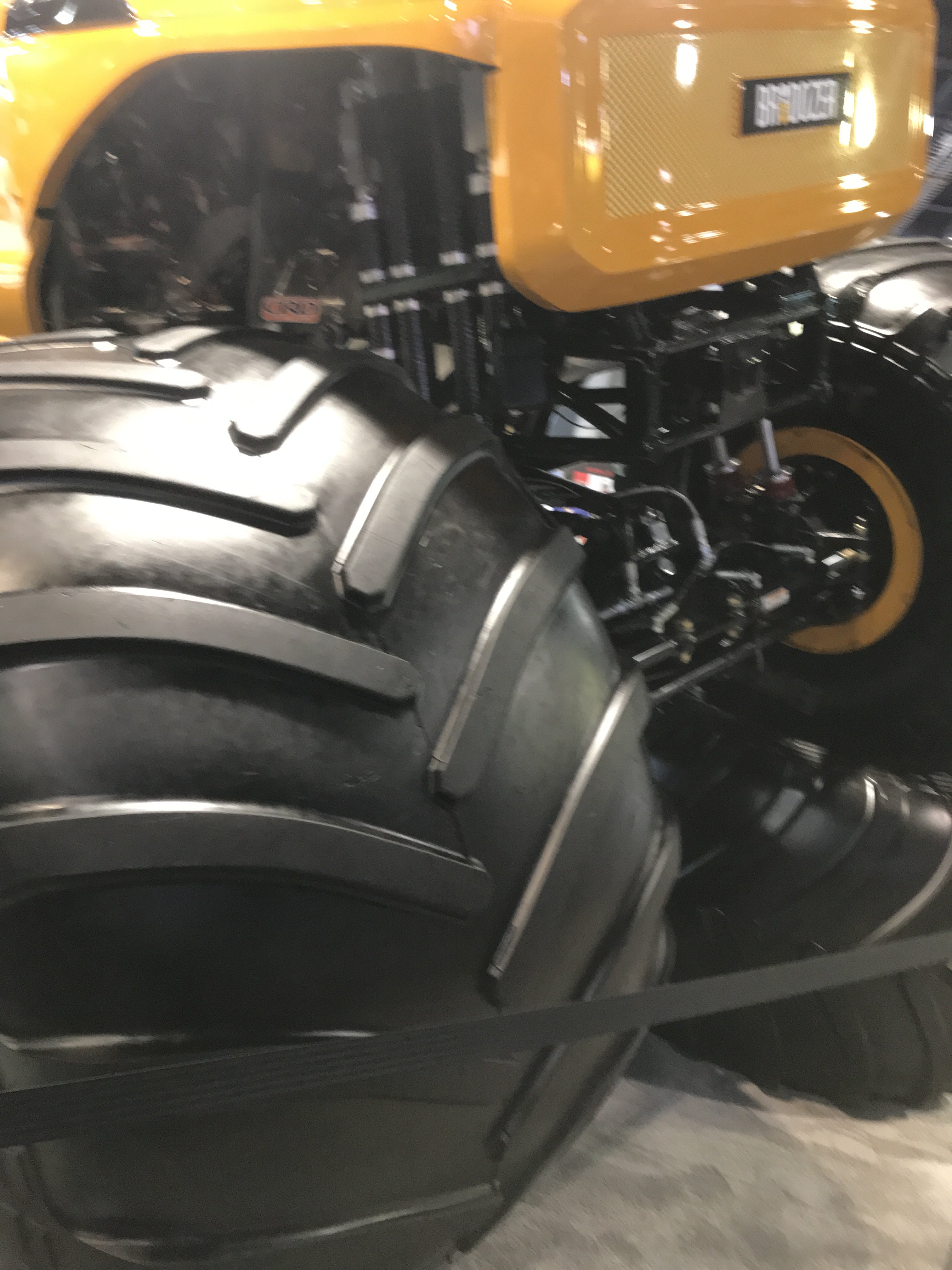
Shell Oil booth had a supercharged Tractor Puller.
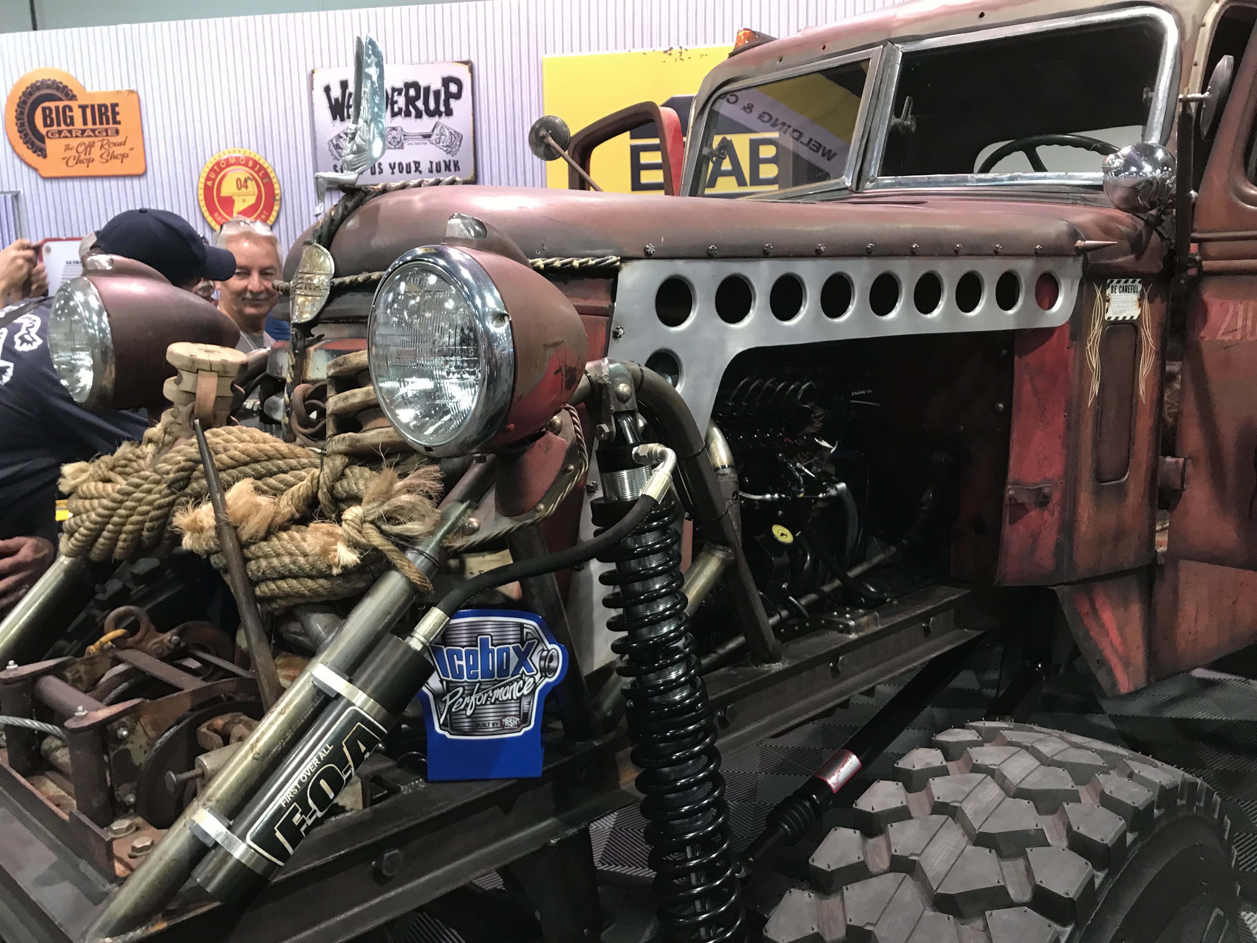
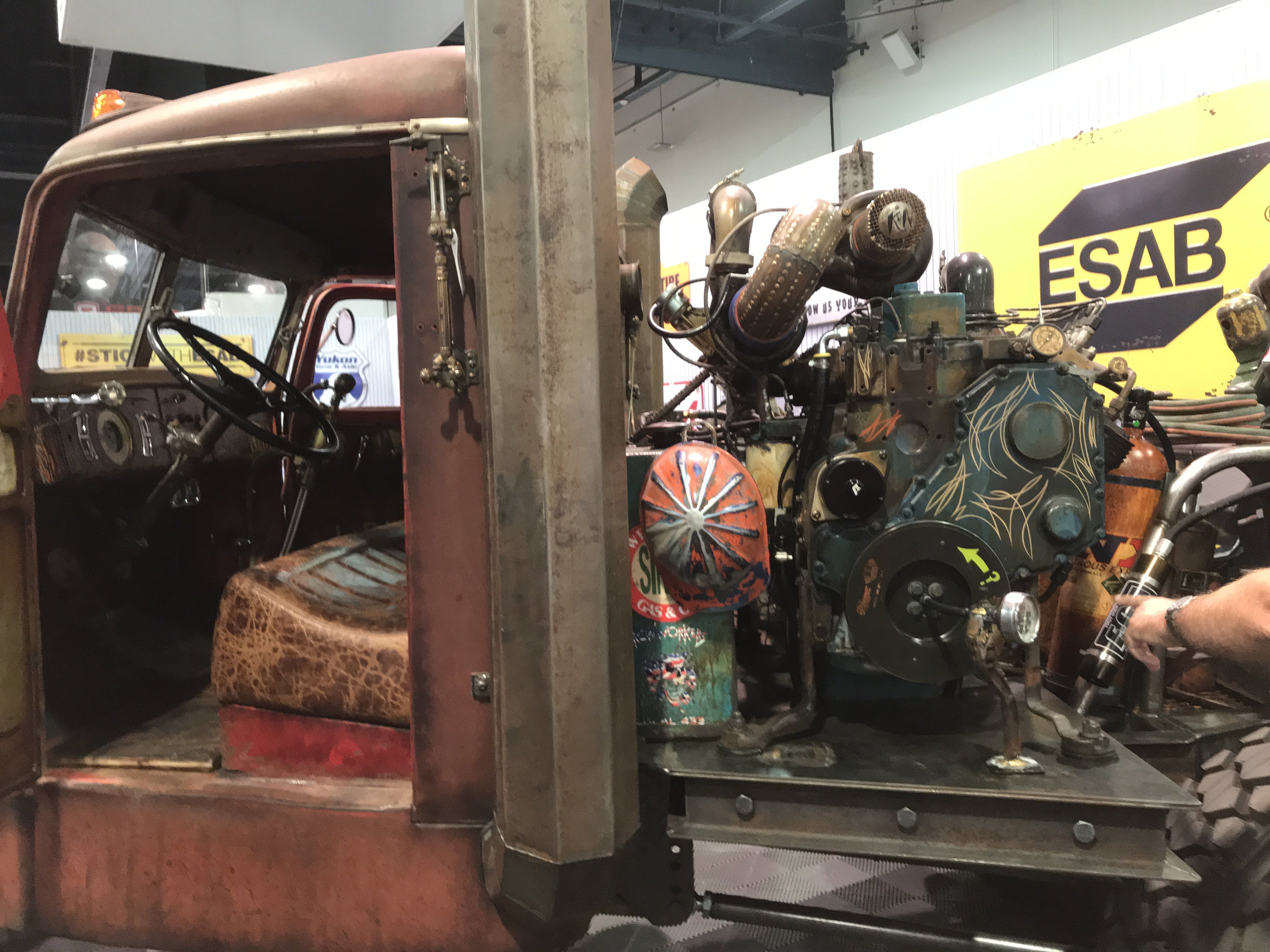
There were many Rat Rods there to demonstrate their creativity. Here is a vintage service truck.
Rear view of the cab and rear bed.
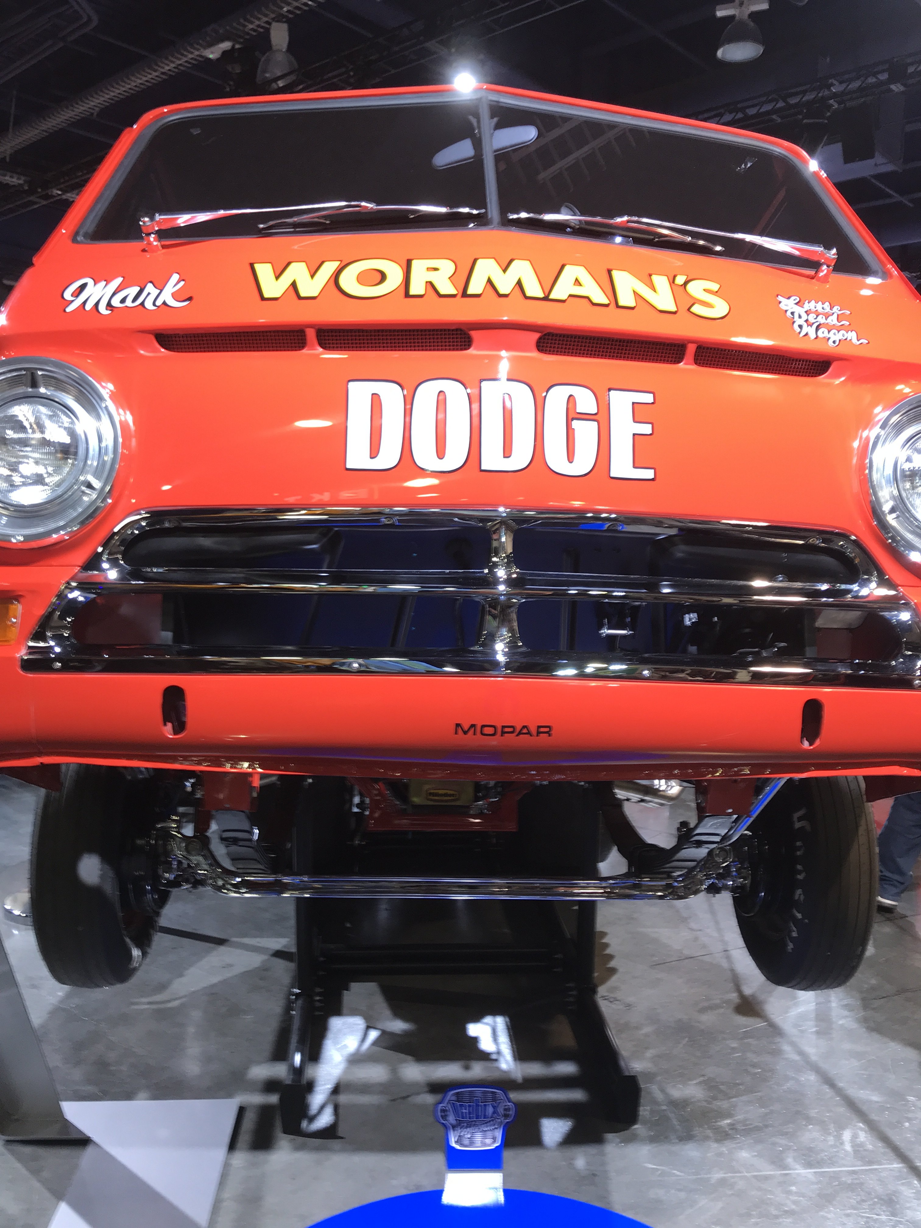
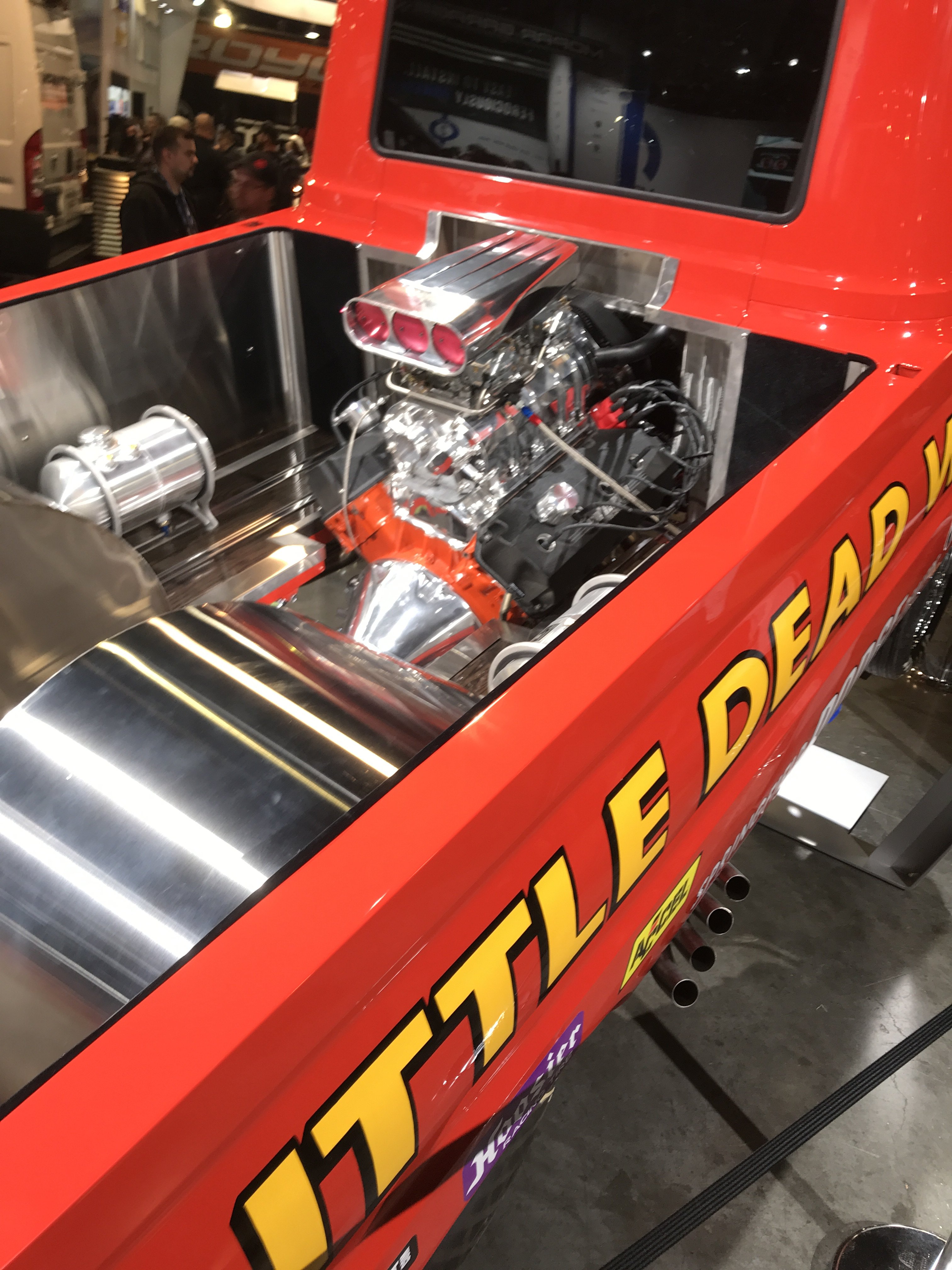
This is spin off the original LITTLE RED WAGON wheelstanding truck that could carry the front wheels the full length of the strip.
-
It was powered by a supercharged Dodge Hemi engine.
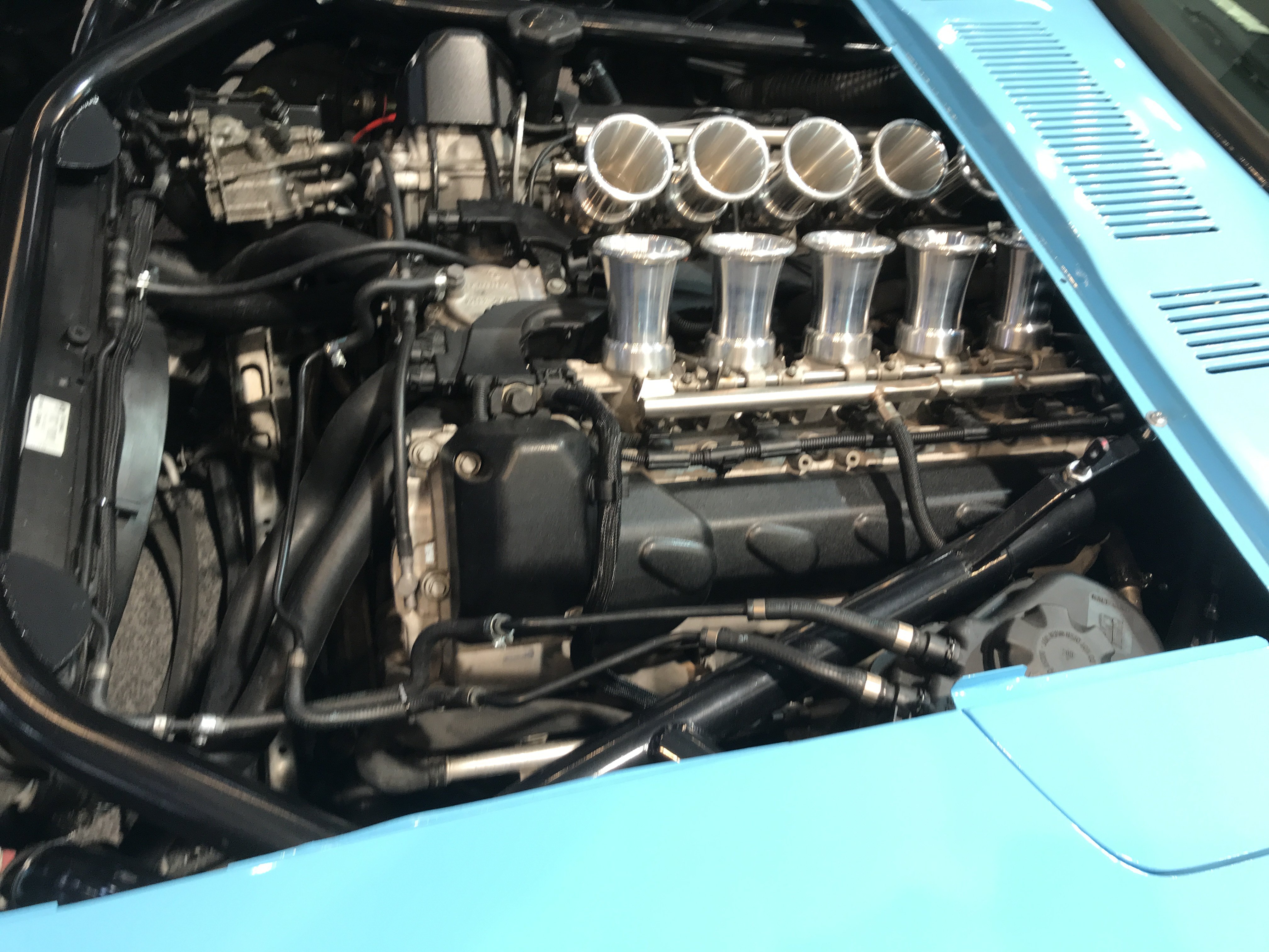
From the You Tube videos, this 240Z had a BMW M5 V10 motor installed on custom made steel tubing frame.
The front end utilized a Rocket Bunny front panel and fender flares.
A universal rear fender flare kit covered the rear tires.
The Street Banditos made a custom LED tail lights for this Z,
Its construction can be seen on You Tube Videos- "B is for the Build". The site has almost 500,000 subscribers. It was entirely built in home garage in Portland, Oregon.
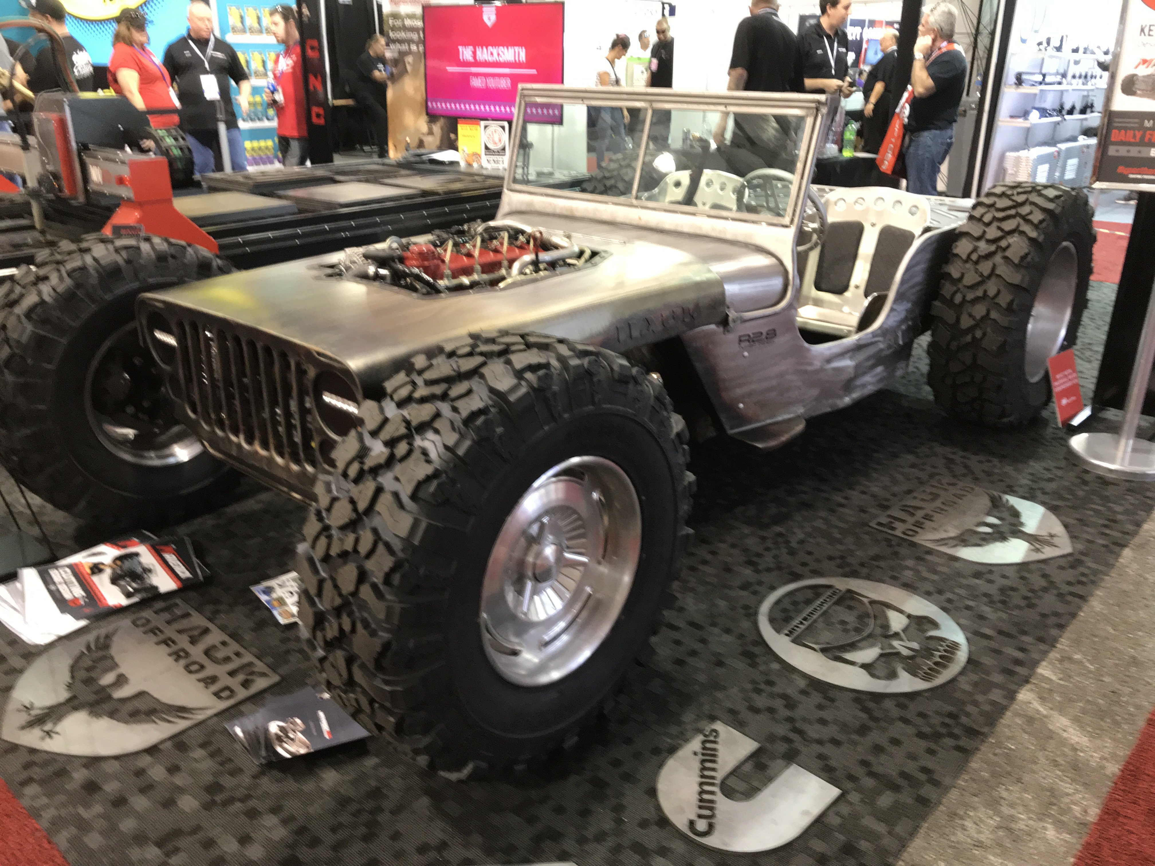
A really chopped and lowered Jeep with giant wheels and tires.
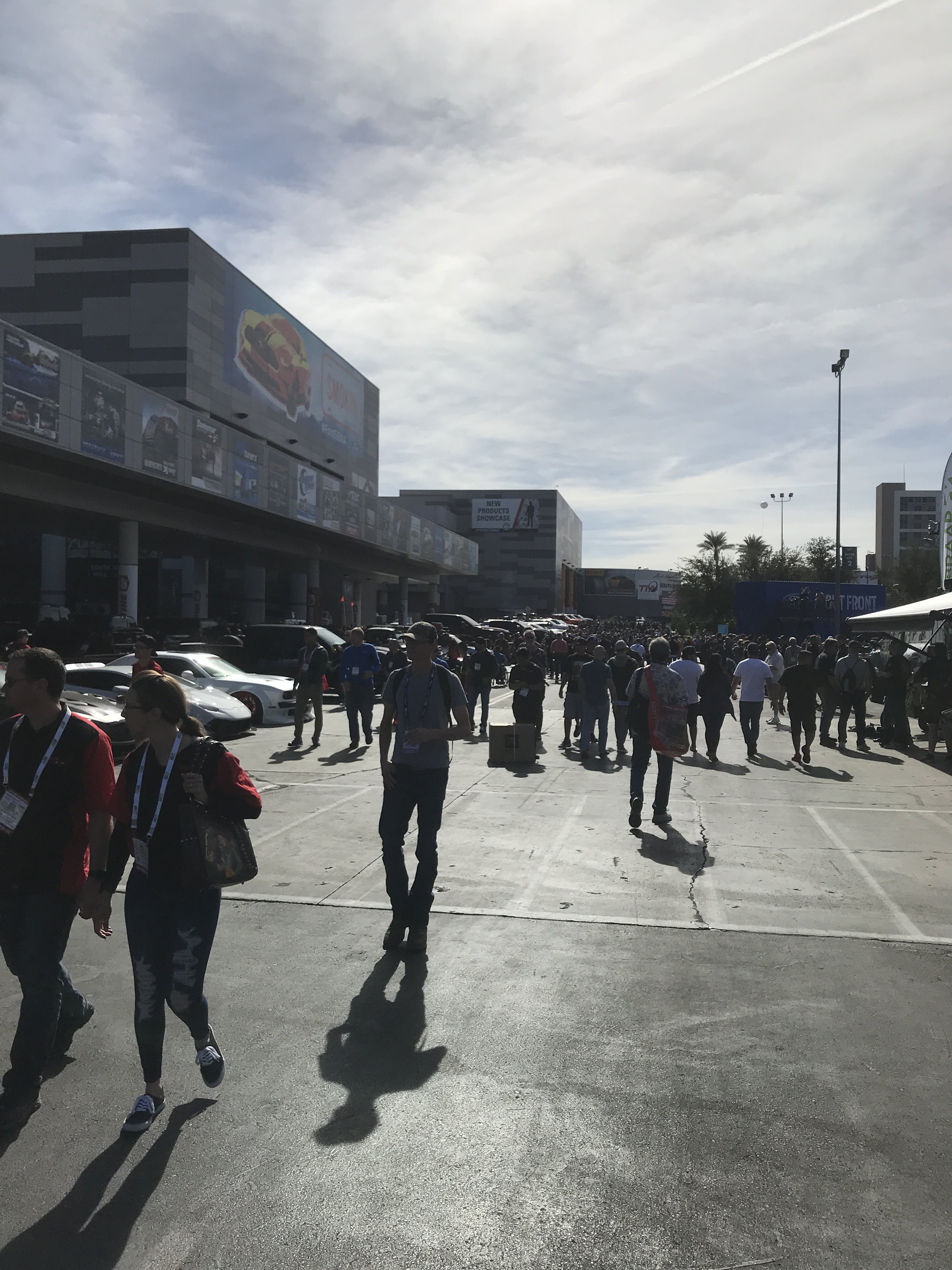
A view of the large crowds of people outside of the main halls.
A wild looking 65 Mustang with a supercharged motor in Pro Street form.
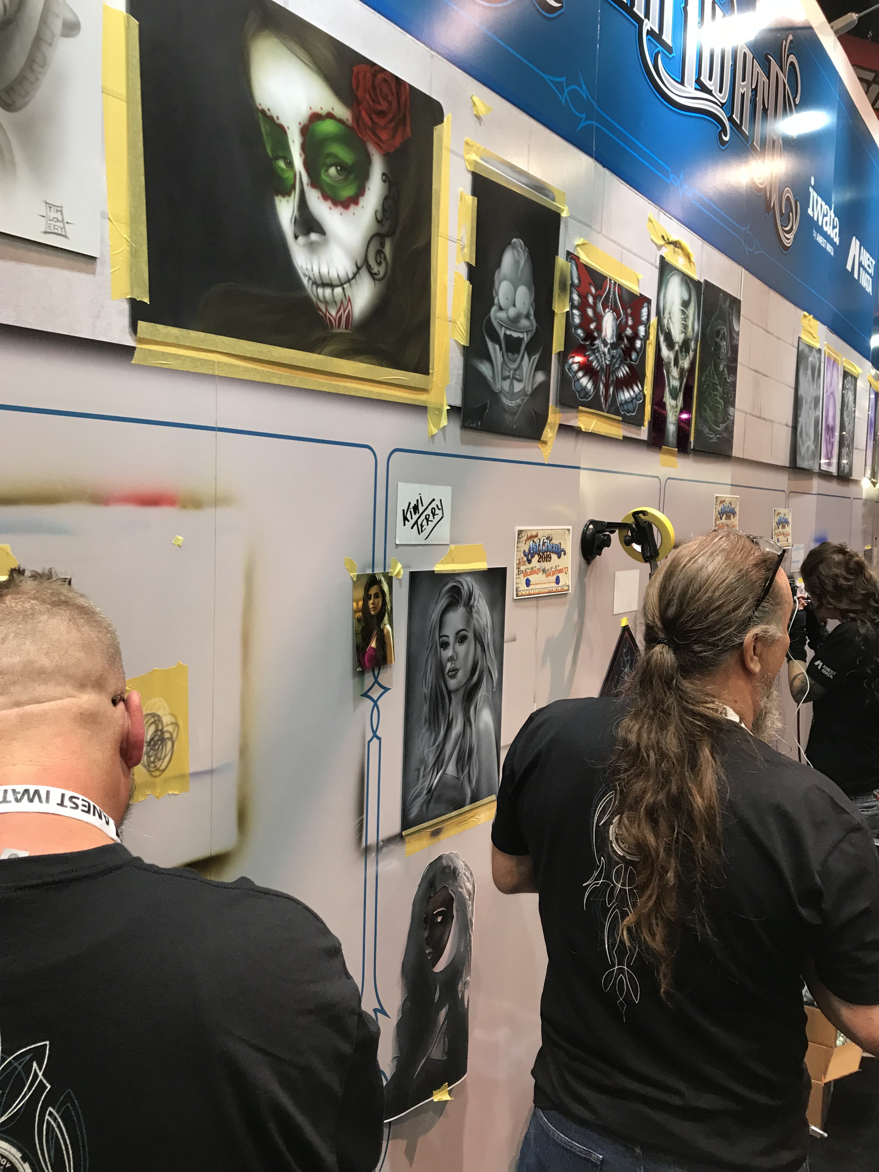
Air brush artists showing their skills.
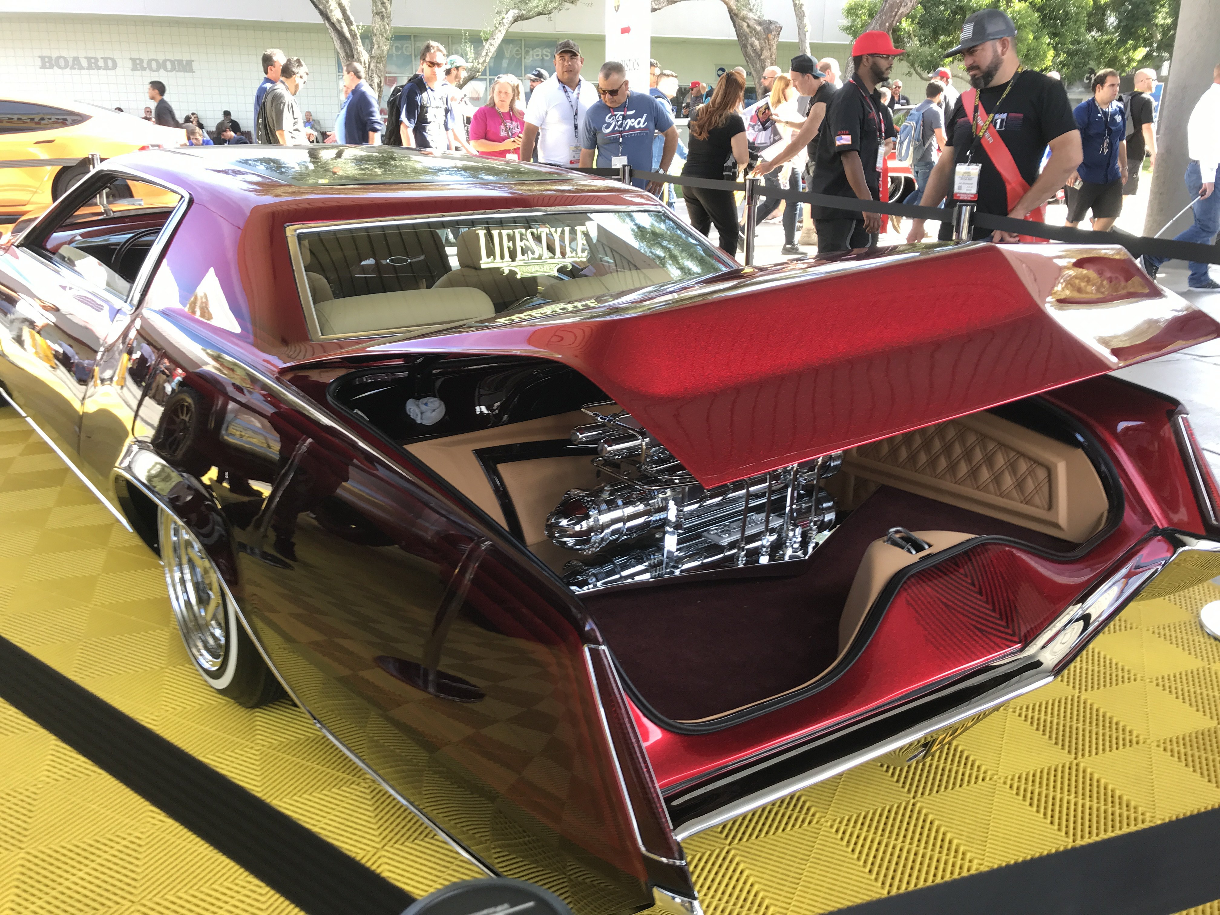
El Dorado low rider with air bag suspension.
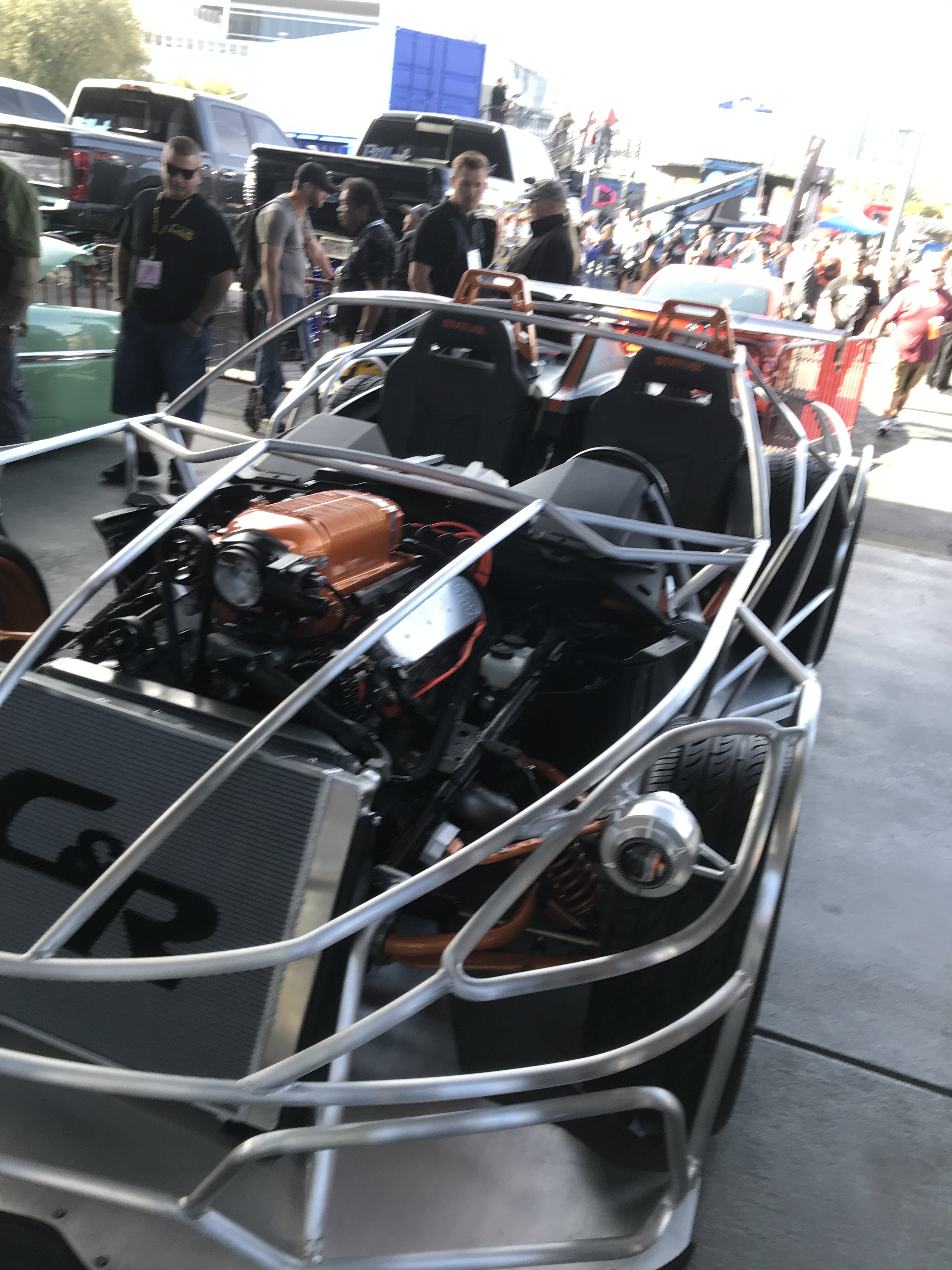
I think this was a modified Miata with tube frame with supercharged motor.
A Monster Truck with Giant Tires climbing rock display.
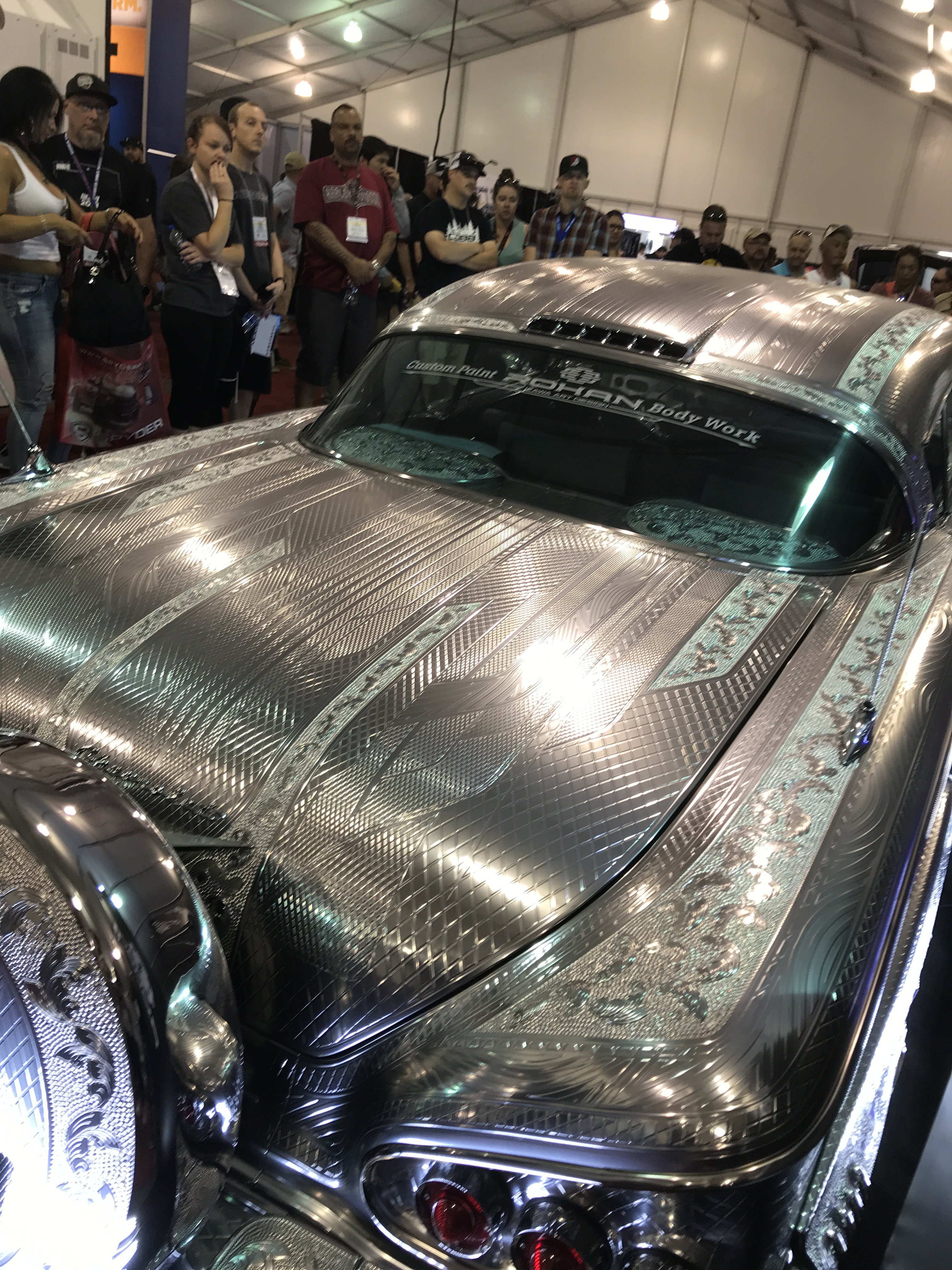
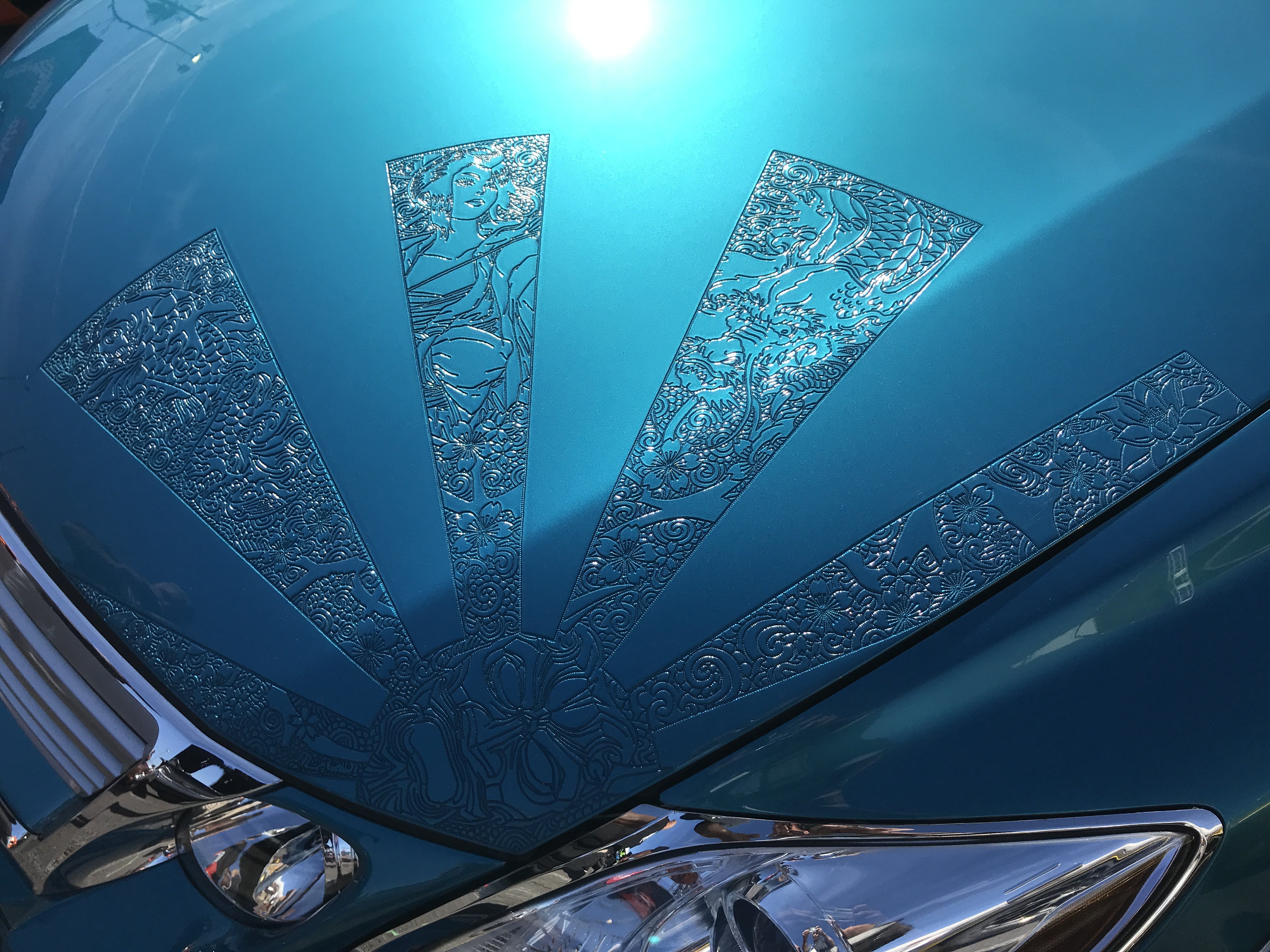
This 58 Chevy has a very unique type of body work-metal paint engraving. This process is spraying metal paint to 1.5M thick engraving the whole vehicle. It is widely popular in Japan and Asia. Thos car took over 6 months to complete.
But really expensive as it is extremely time consuming. Enlarge the photos to see the workmanship. Unreal!!!
Another example of type metal engraving. Don't forget to enlarge this pic to really see the workmanship.
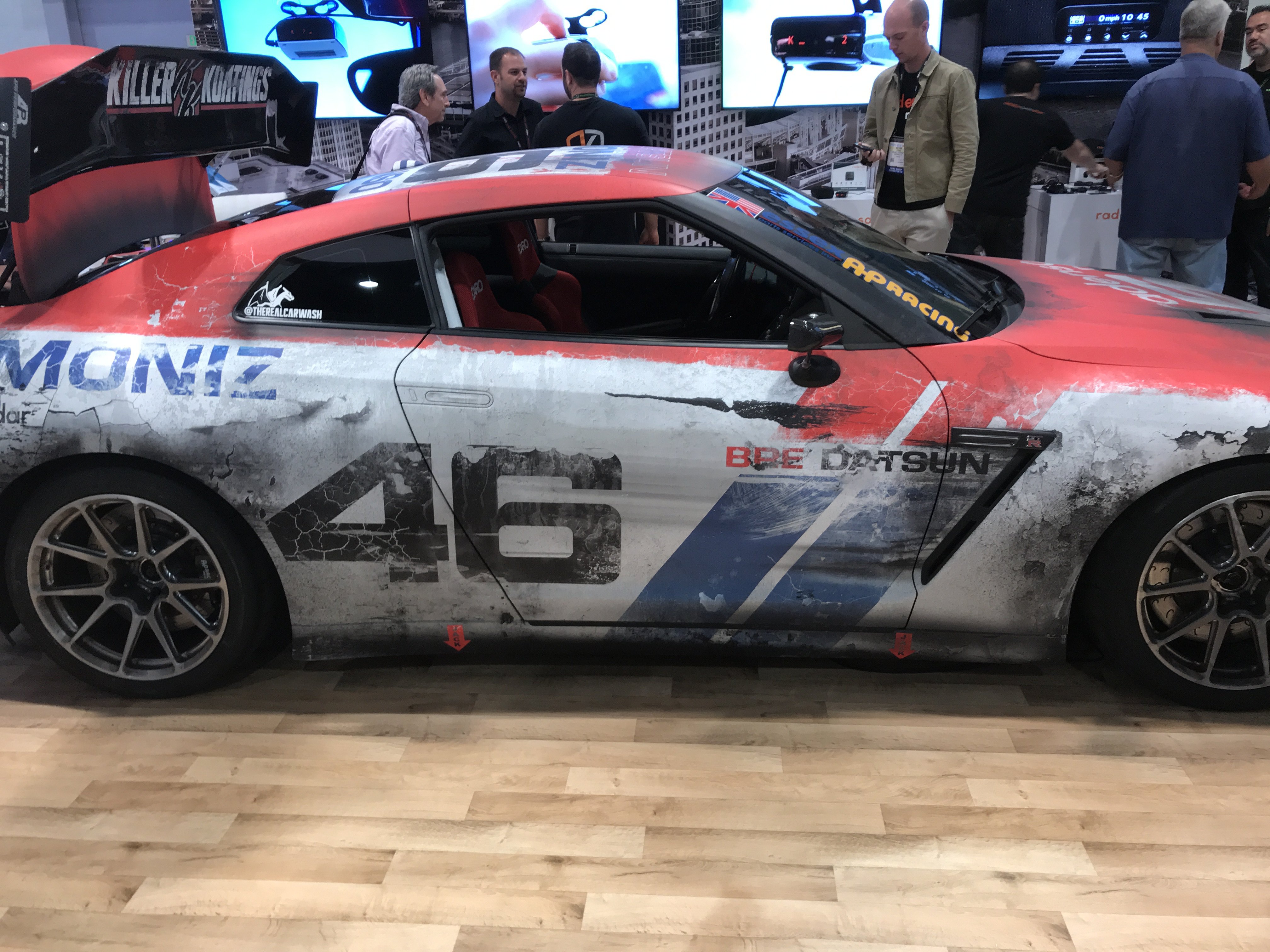
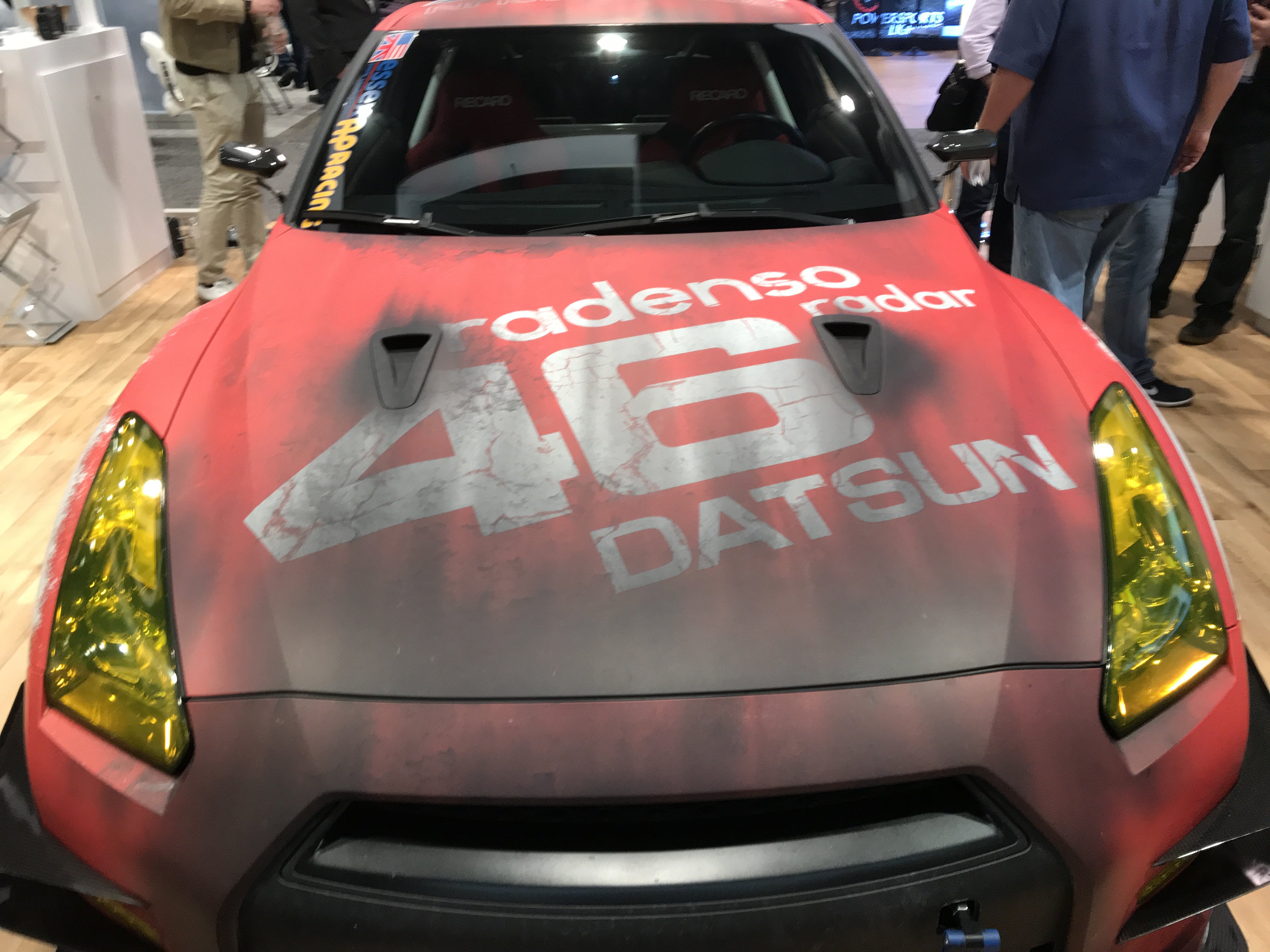
This 370Z was painted and body worked to replicate a beat up racer. All those dents and scrapes were created. They
created a Rat Rod Nissan Z to me.
Only a keen eye would notice that gaps, edges, body panels were not distorted. The paint job was manipulated to create
the worn and damaged effects. Similar to what Rat Rods do.
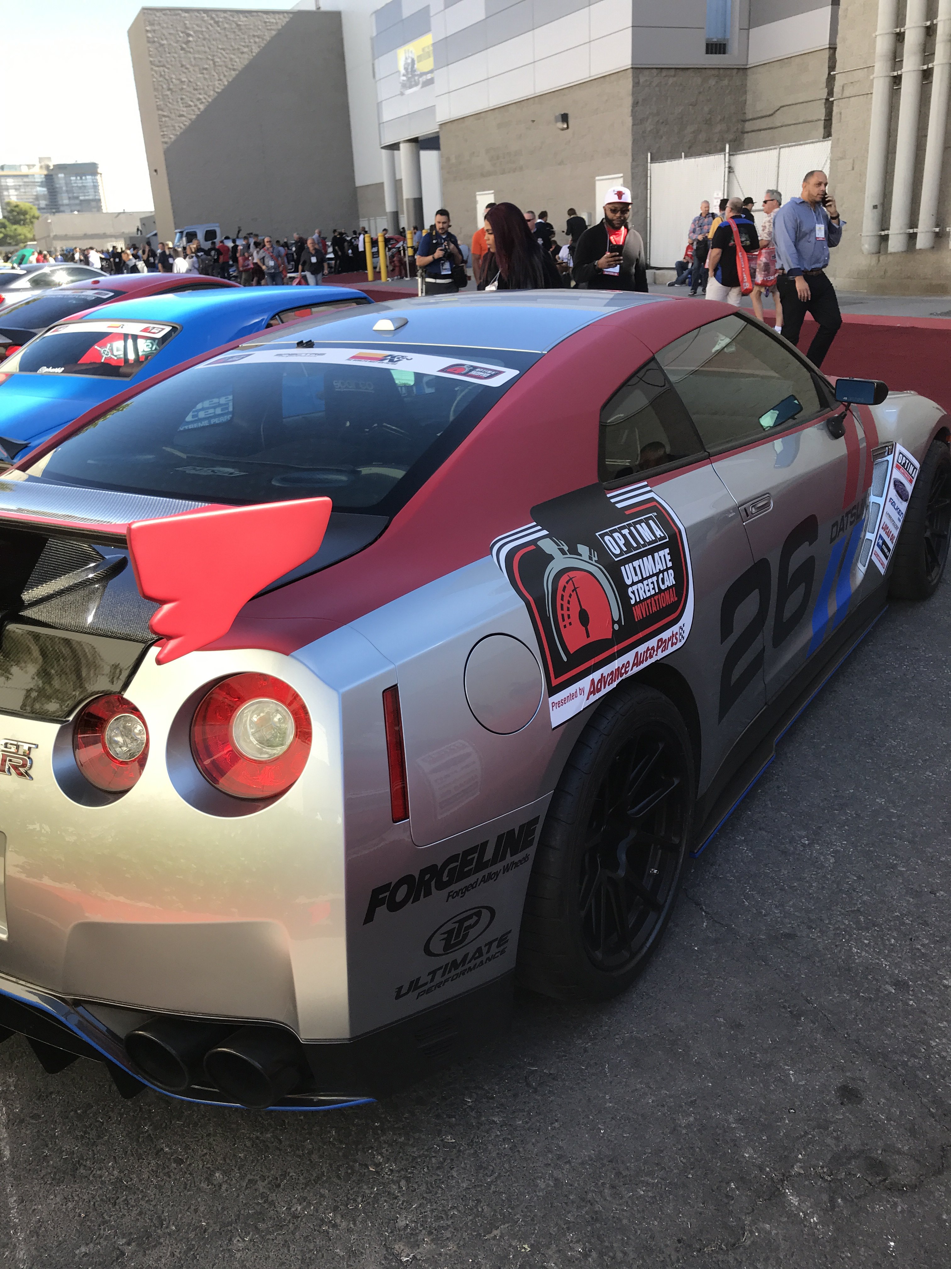
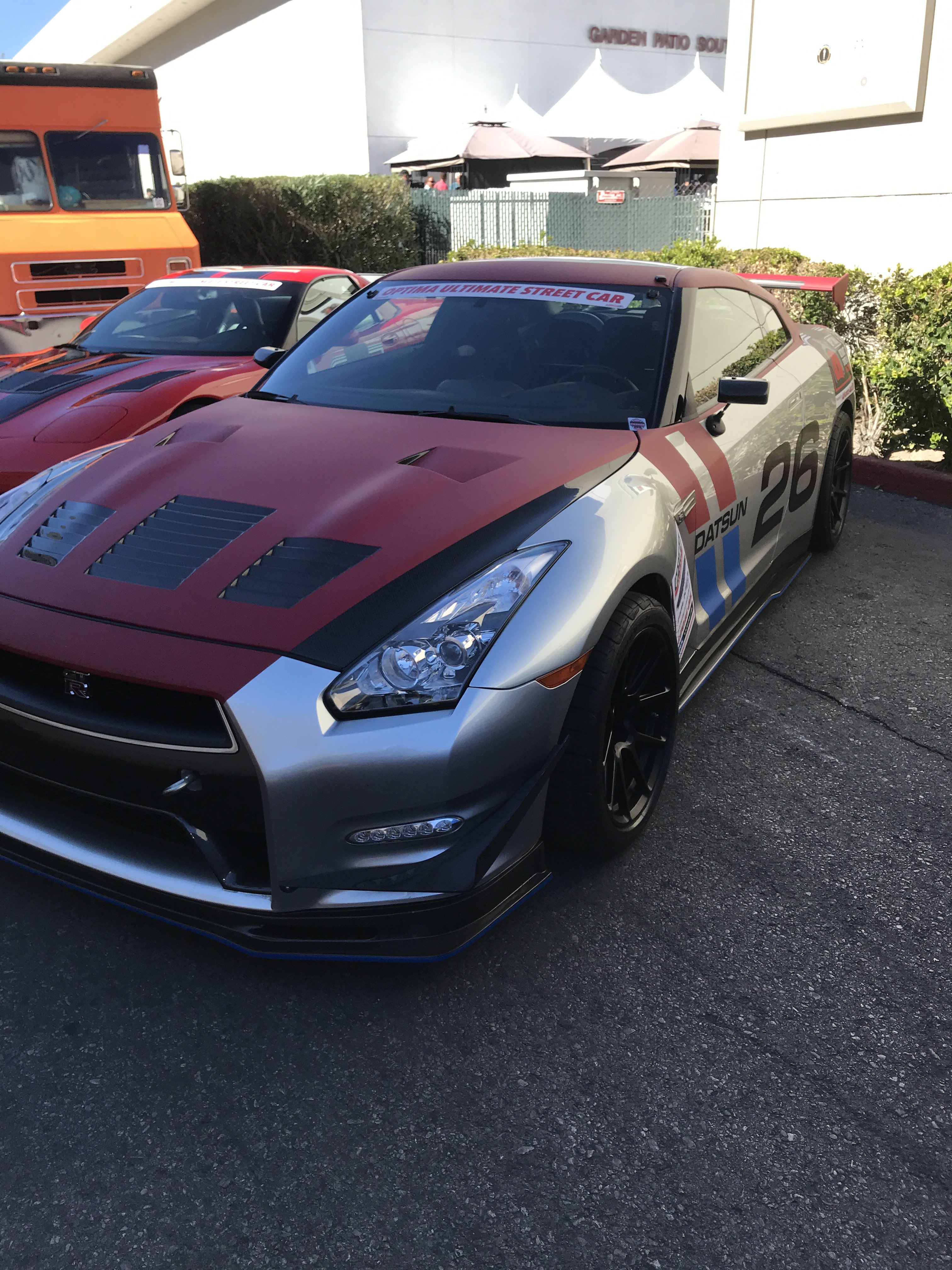
Nissan Skyline Z was in Optima
Ultimate Street Car Event that raced around the county.
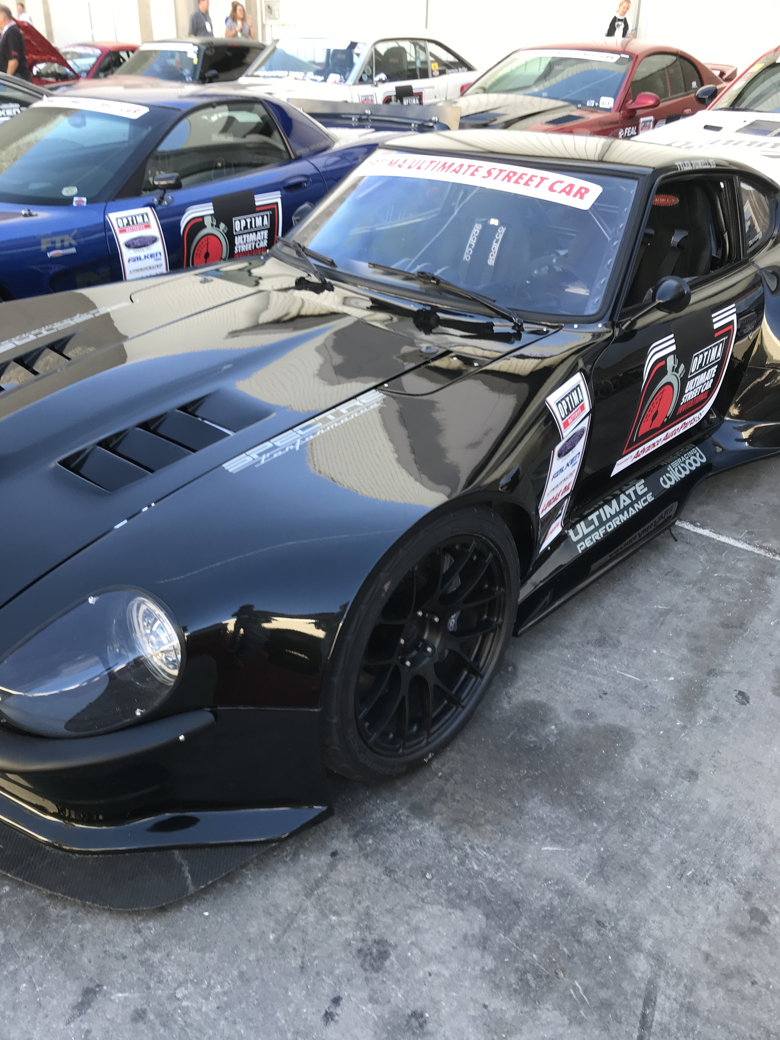
Another Optima Race Z
Not sure but think this Z had a LS motor with T56 trans. The car was so low you couldn't see underneath.
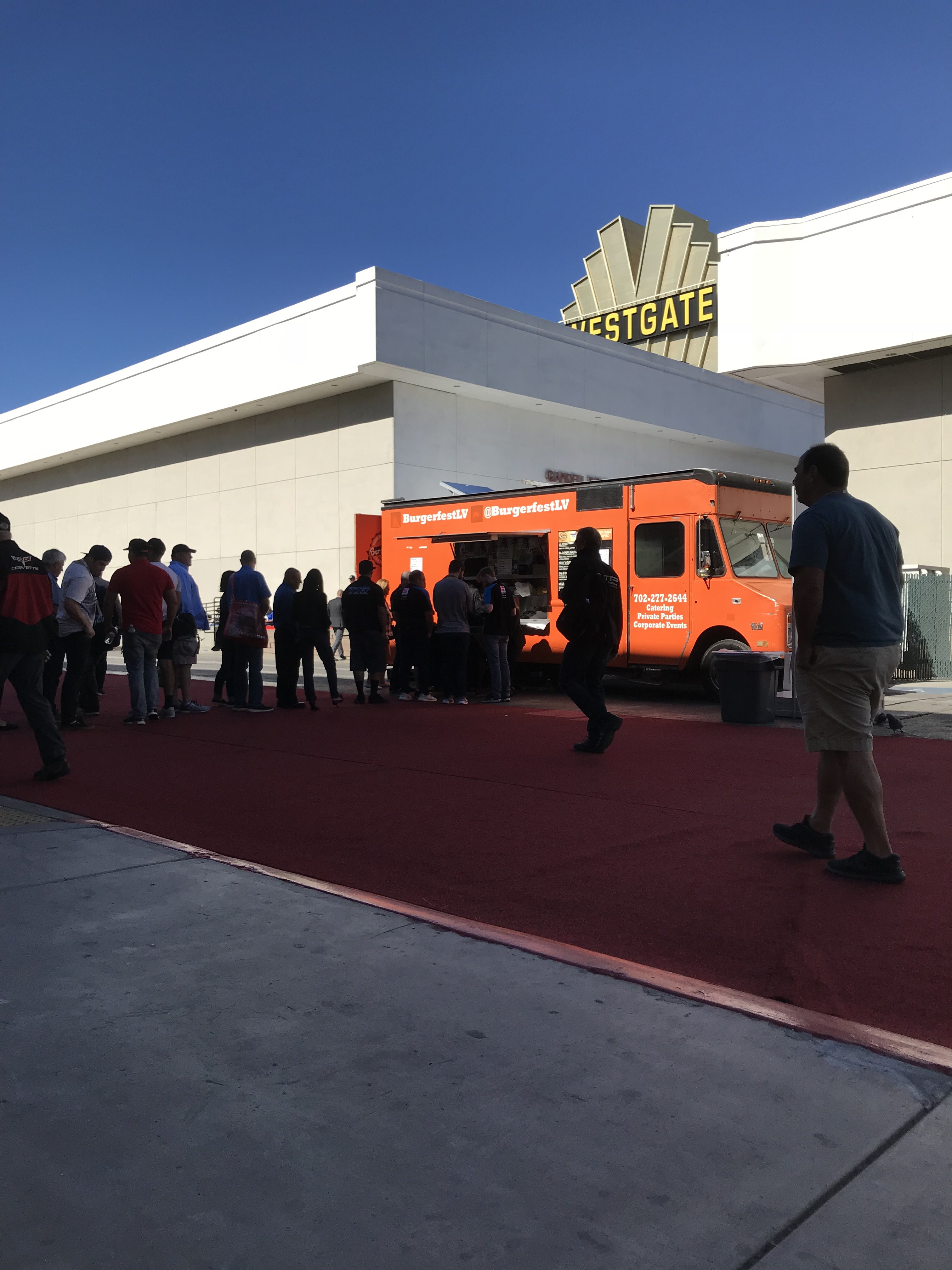
There were about 10 Food Trucks all around the SEMA SHOW to provide a wide variety of food selections(Chinese,
Mexican, Middle Eastern, etc)
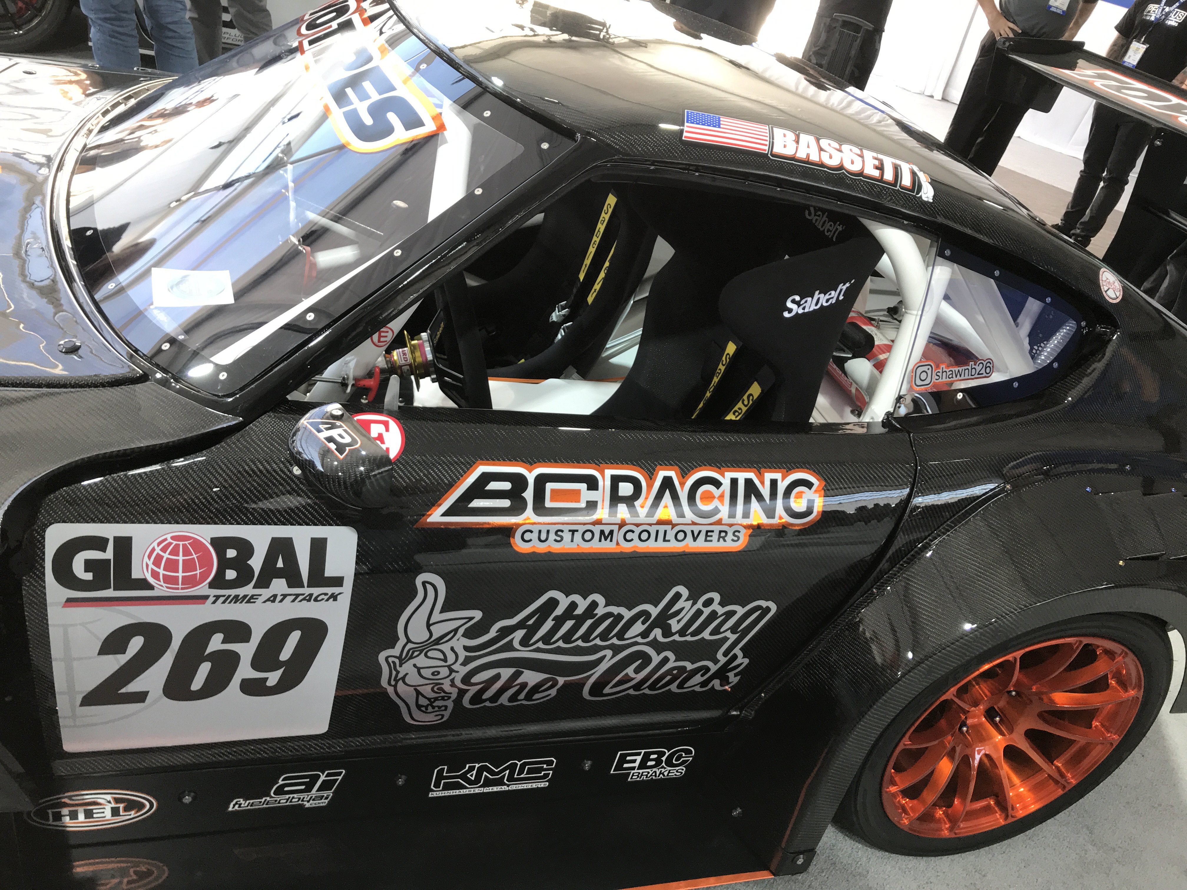
Another LS Z Racer;
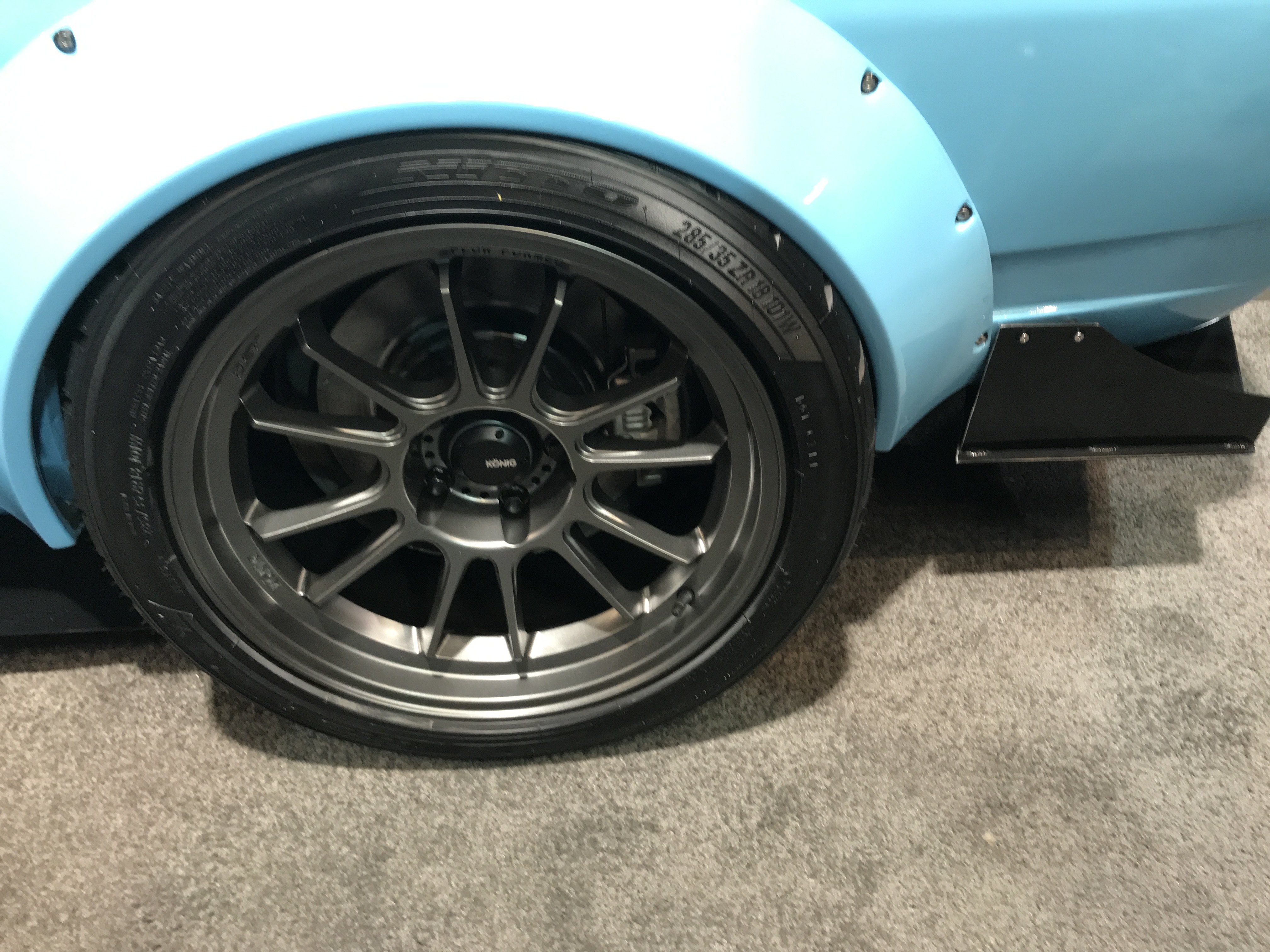
Tires and wheel look small for the flares but looks like there was a lot of carbon fiber parts on it.
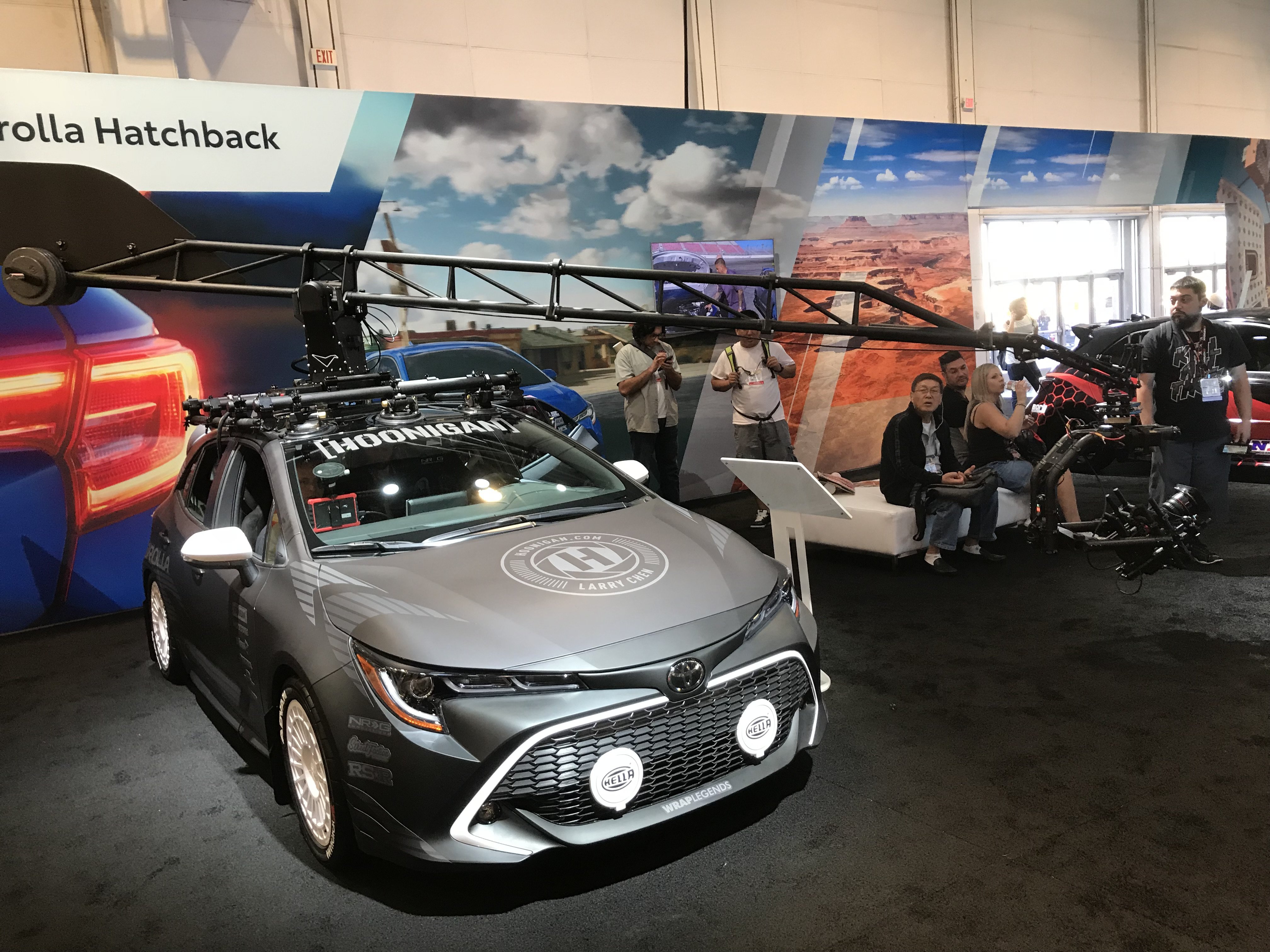
Ever wonder how the movie studios film those wild car chases and crashes. A modified Toyota with computer controlled
360 degree crane on its roof, that is how!!
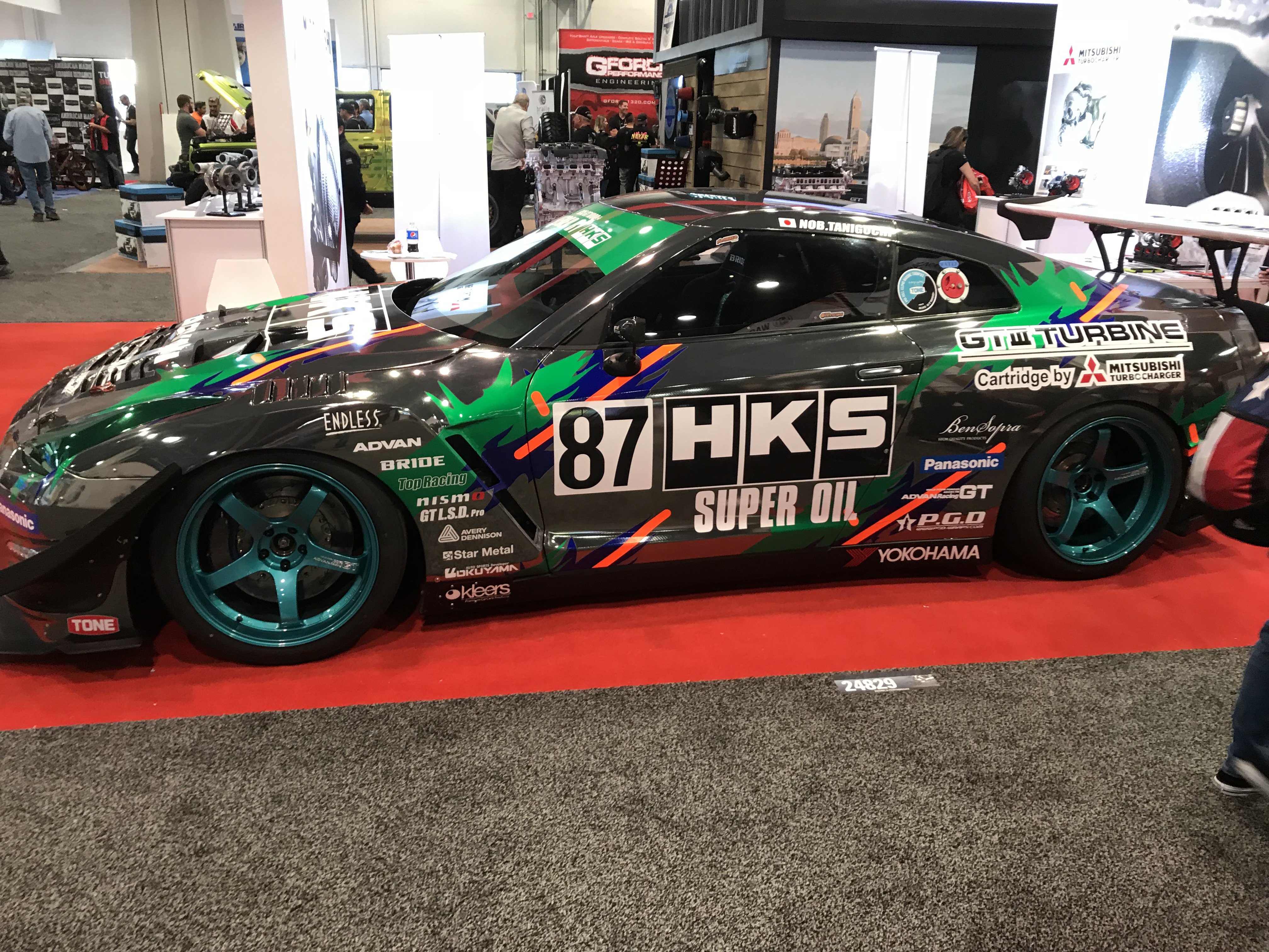
HKS 370Z RACE CAR
Auto Body & Paint section of the show( even had spray paint booths).
WELD UP another one of their RAT ROD creations. Note how the front end's black roses-represents death. As you move
move to the engine's red roses
represents love/hope. Then to the rear of the car. the yellow bright paint job.white interior and white wall slicks represents clean/ purity. This car was made for a cancer recovery individual. Very Artistic!!
-
DonH, Thanks for compliment. I finished the rear hatch and seam sealed all of the seams.
.pic of the finished hatch.
.
Front area of the floor pan resealed with sprayable seam seal.
View of the main frame rail seam sealed.
closeup of seam sealing frame connector and rear crossmember.
Rear frame and rear body panel seam sealed.
I wanted to put more seam sealer on the bottom to provide more rust protection and sound abatement but ran out of sealer.
I am going to the Sema Show in Vegas next week and will try to post some pics( especially 240zs) from there.


.JPG.5909c8c321c1cd74462e21646ea48787.JPG)

 Also, Epoxy Resin is much stronger than Fiberglass resin
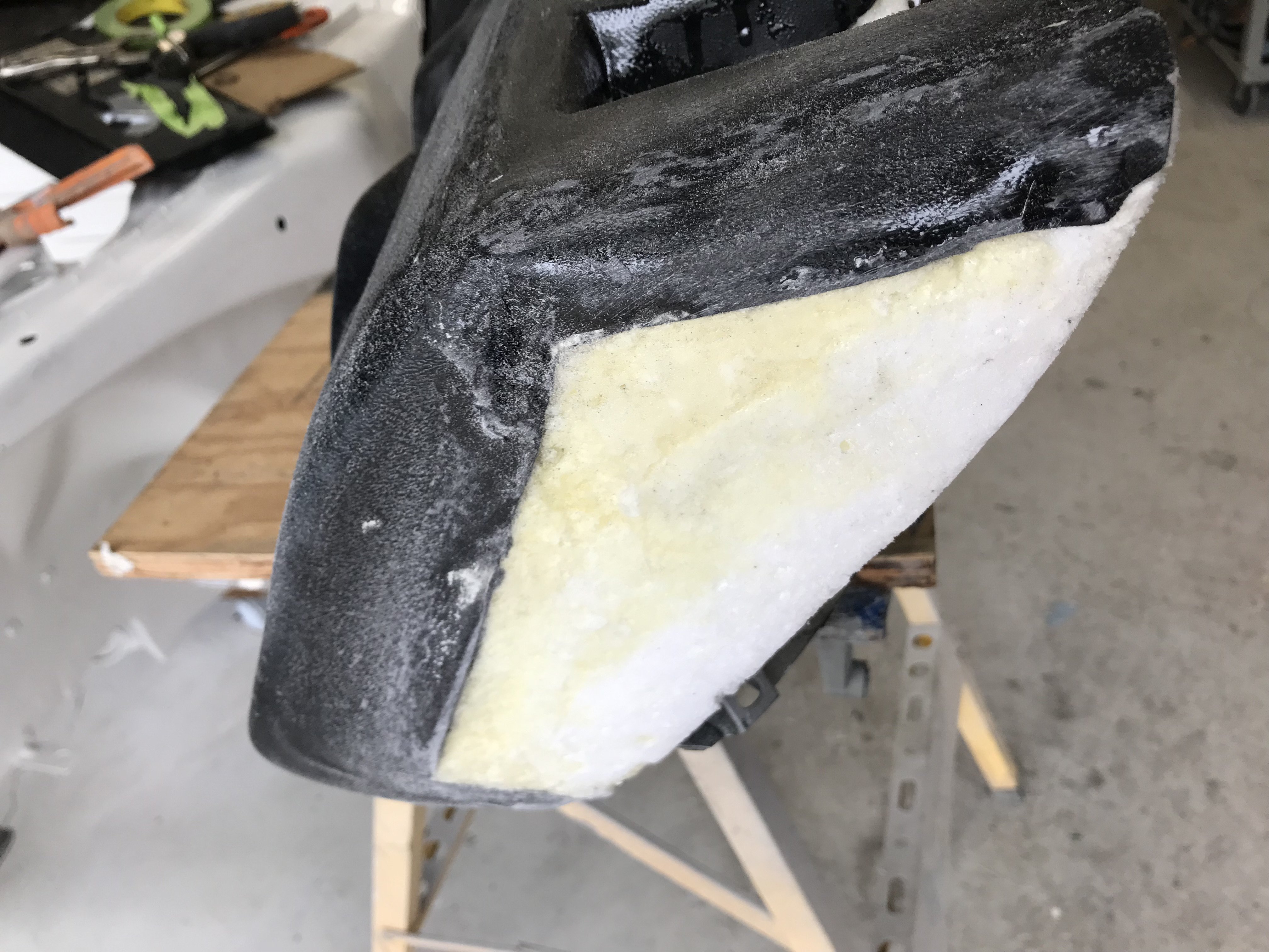
 Note-Blending areas between replacement foam section and original dash are smooth.
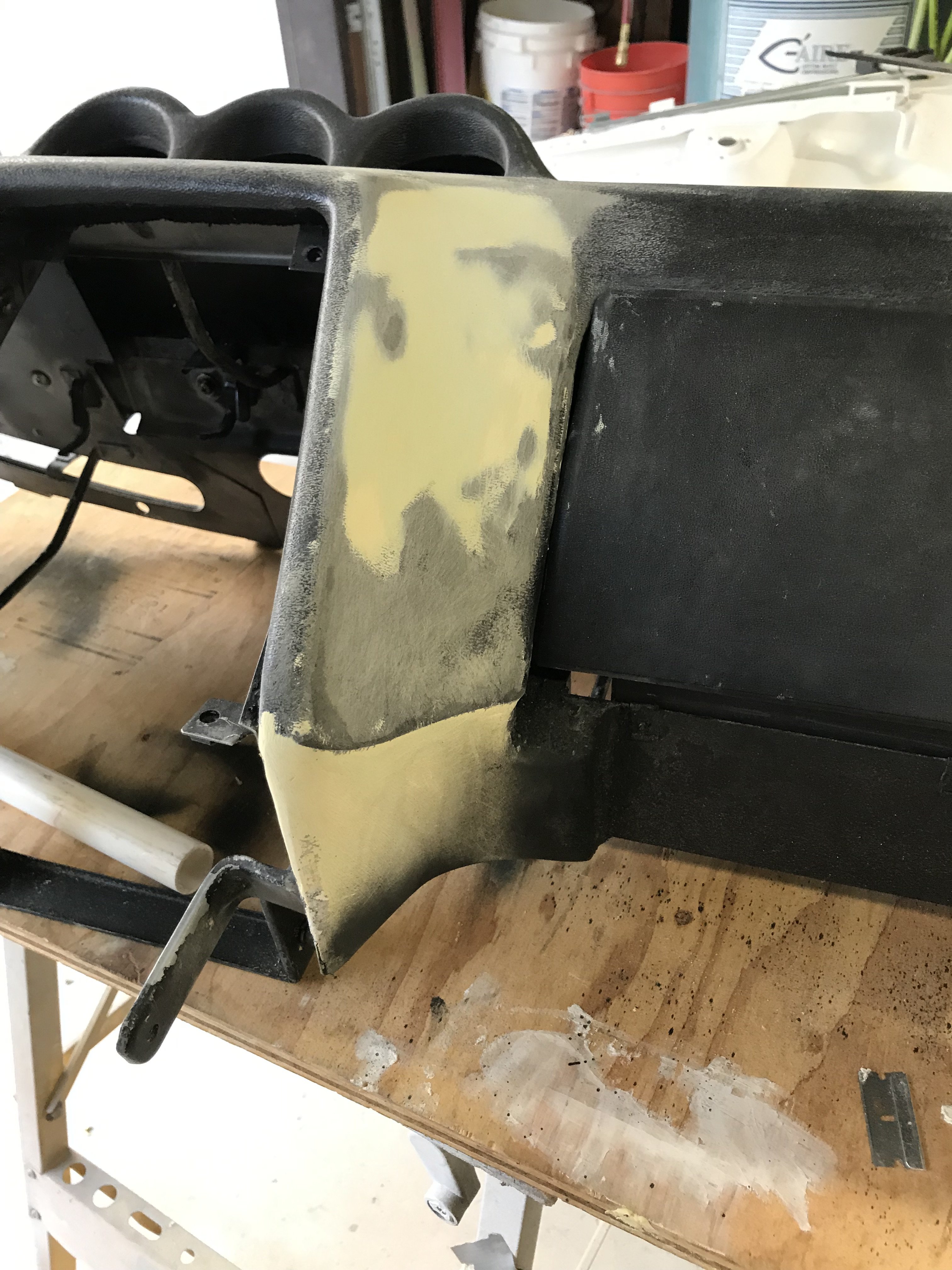
 All of the repaired areas were next epoxy primed.
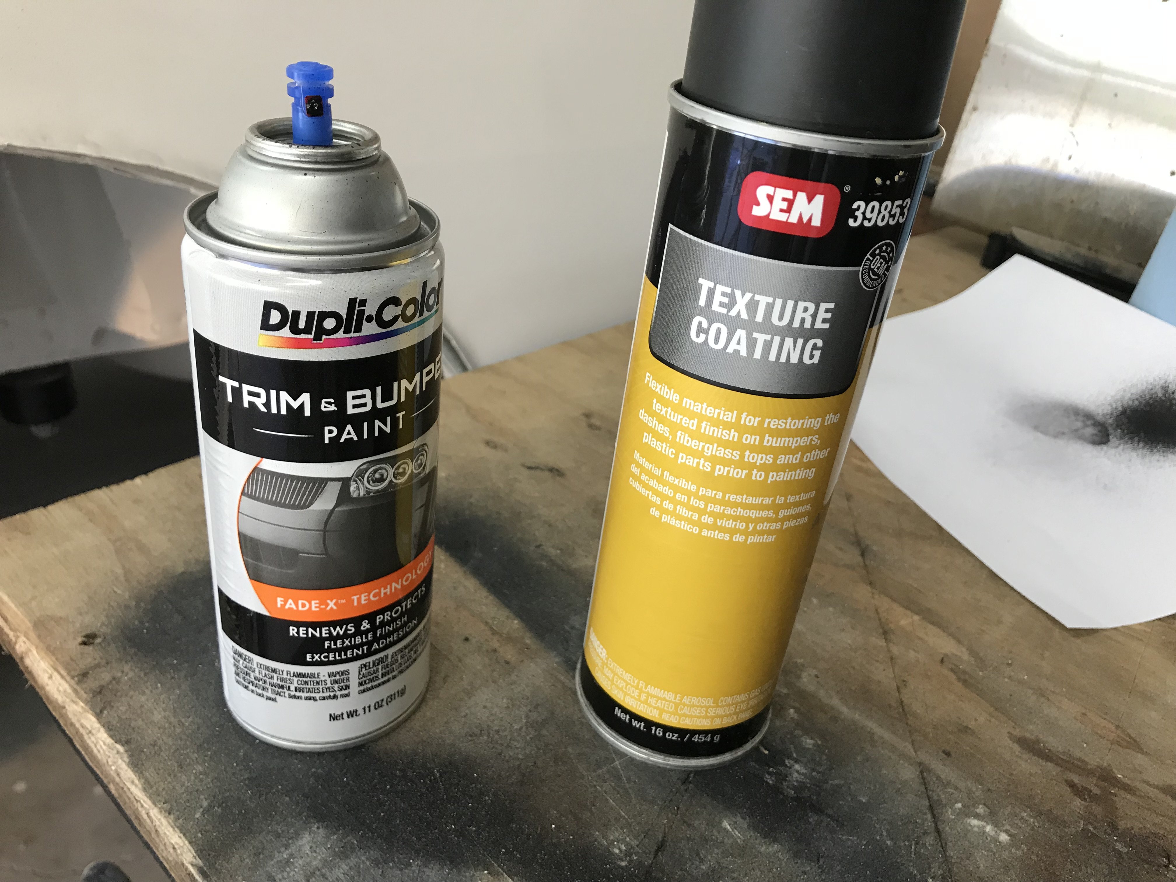
 Top View of Finished Dash Board.
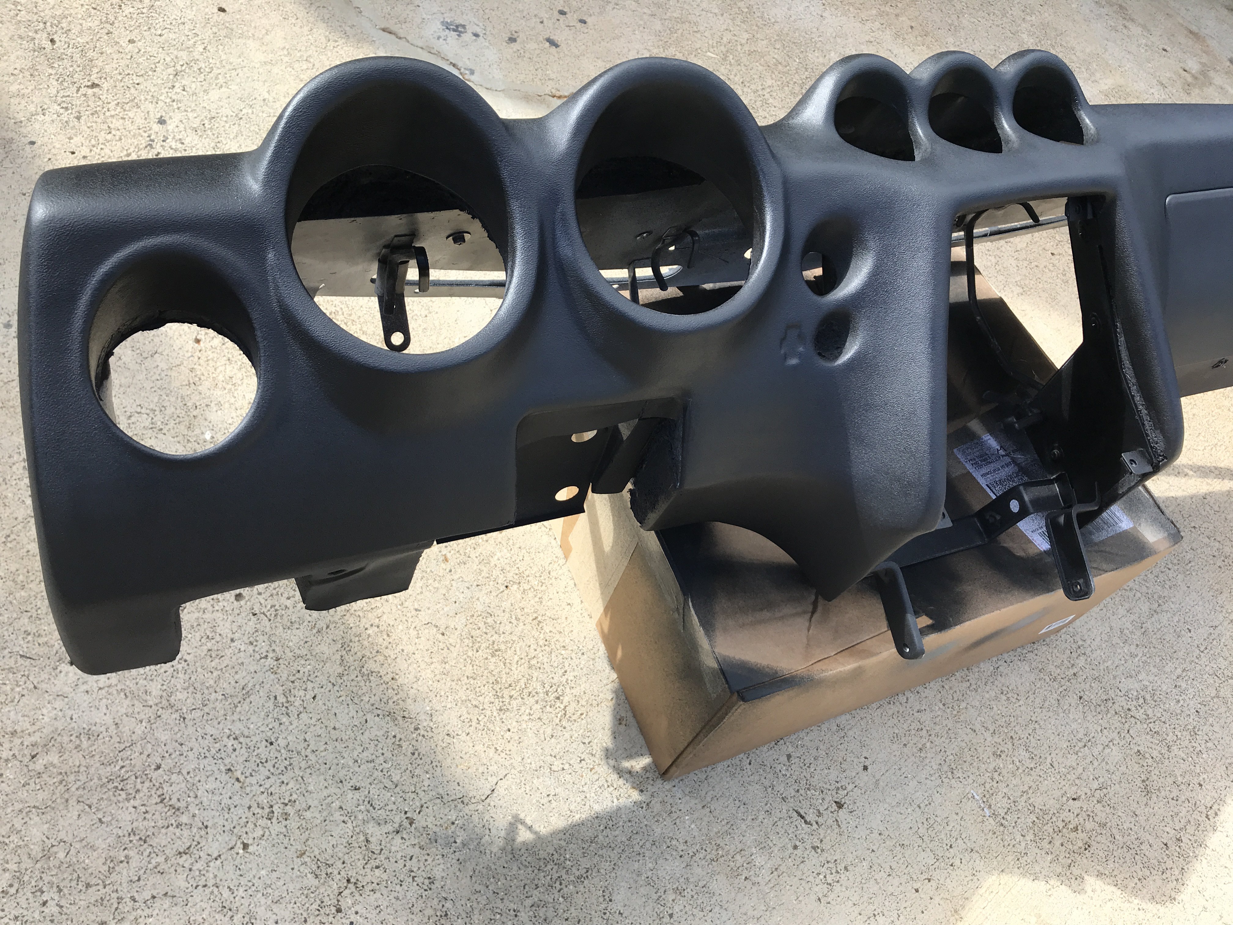 Left Front View
 Cnter View with Center Section and Glove Compartment installed
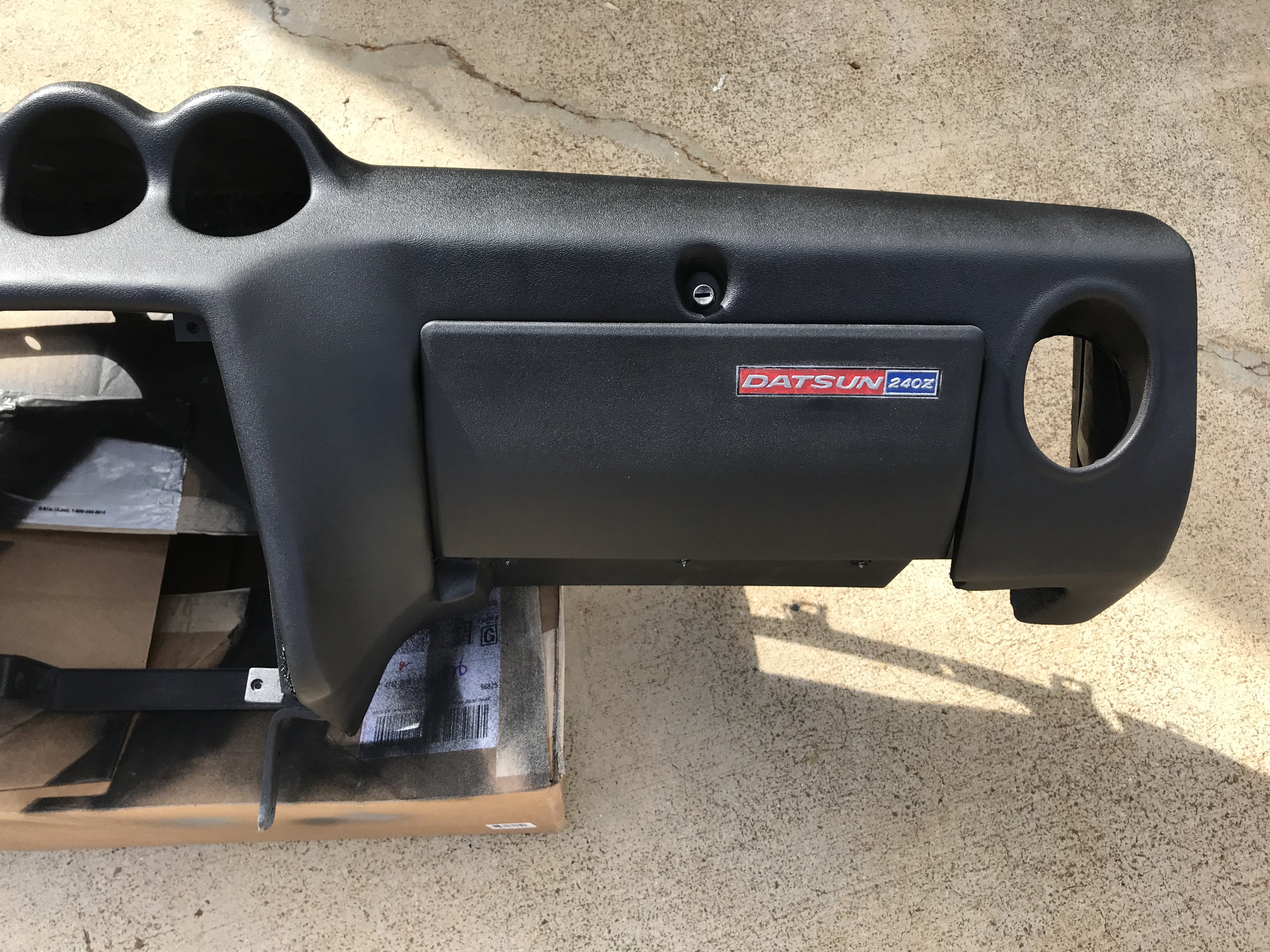 Right Front View
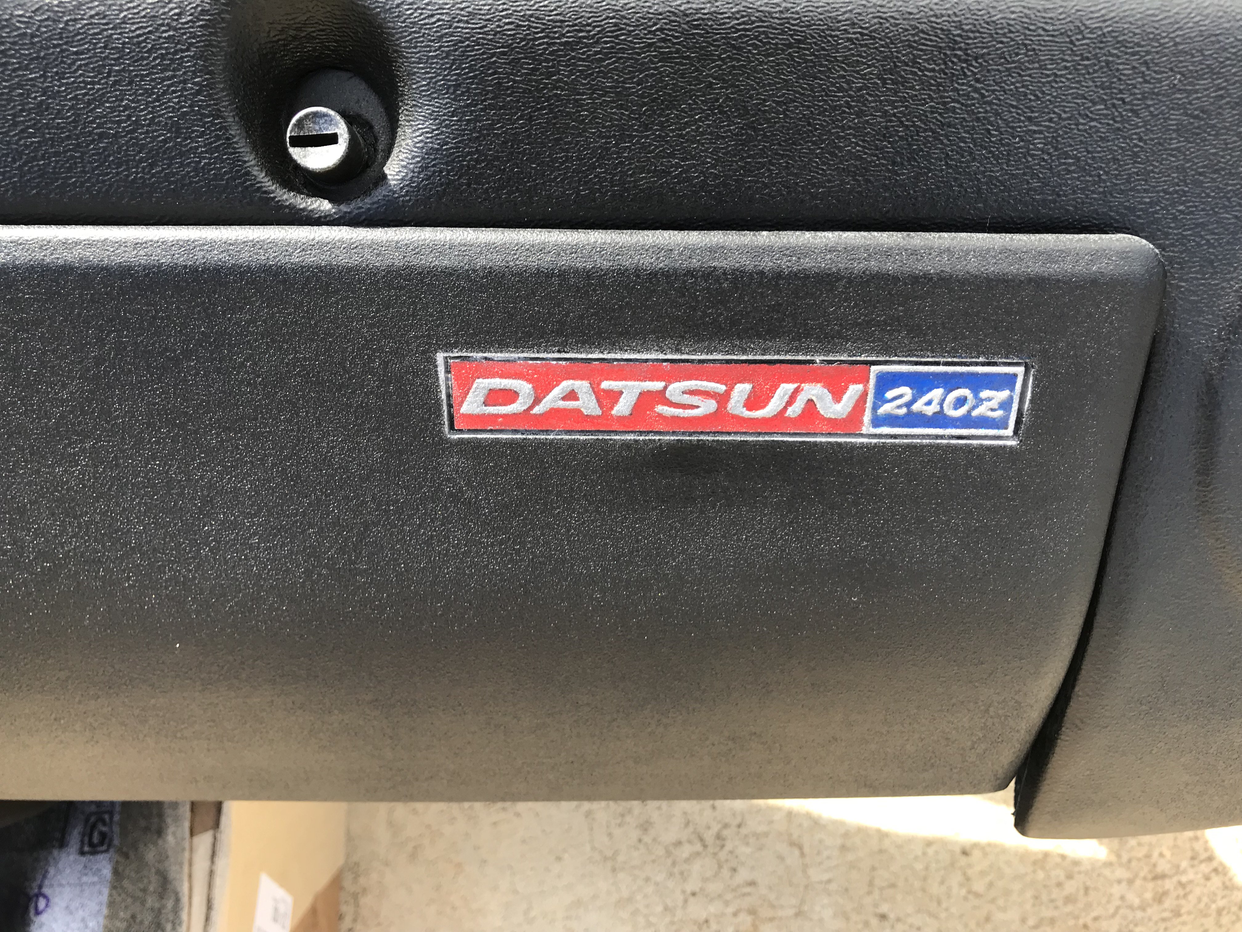 Closeup View of Glove Compartment Emblem
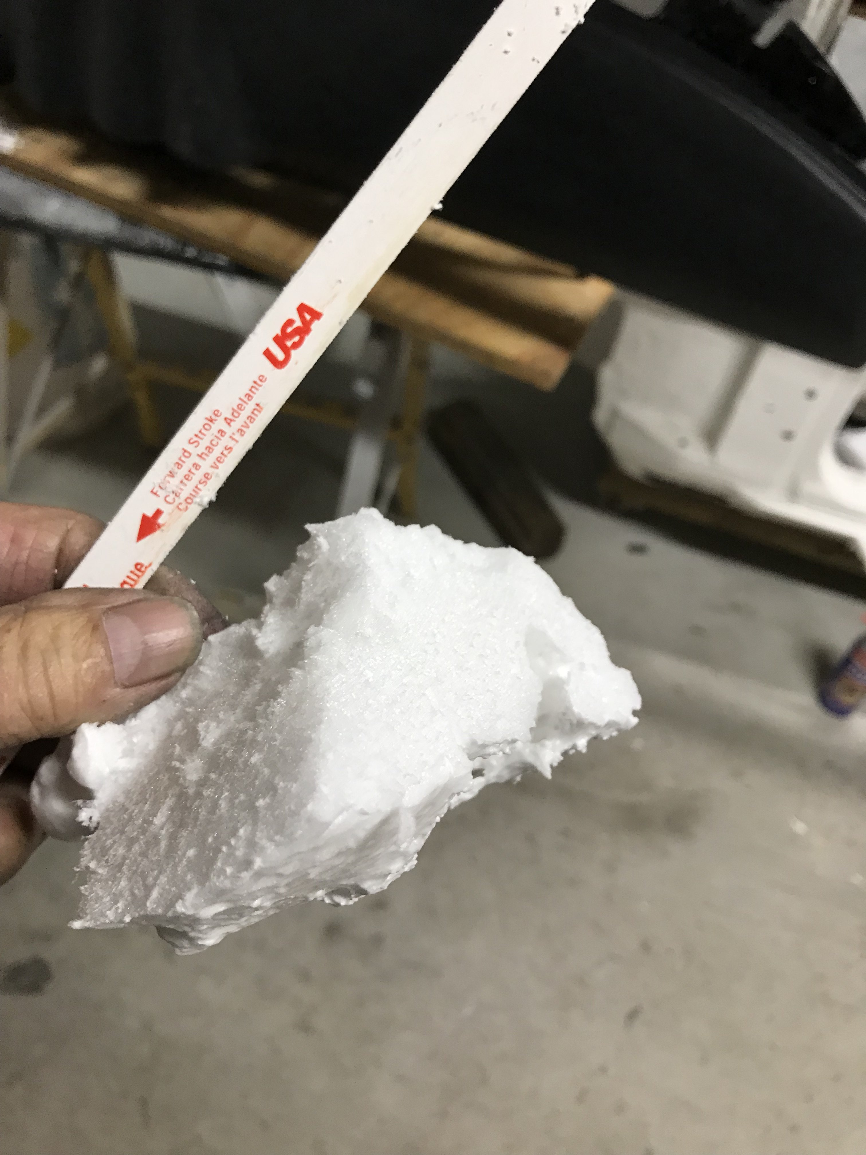 Note-The smooth cut of the foam.
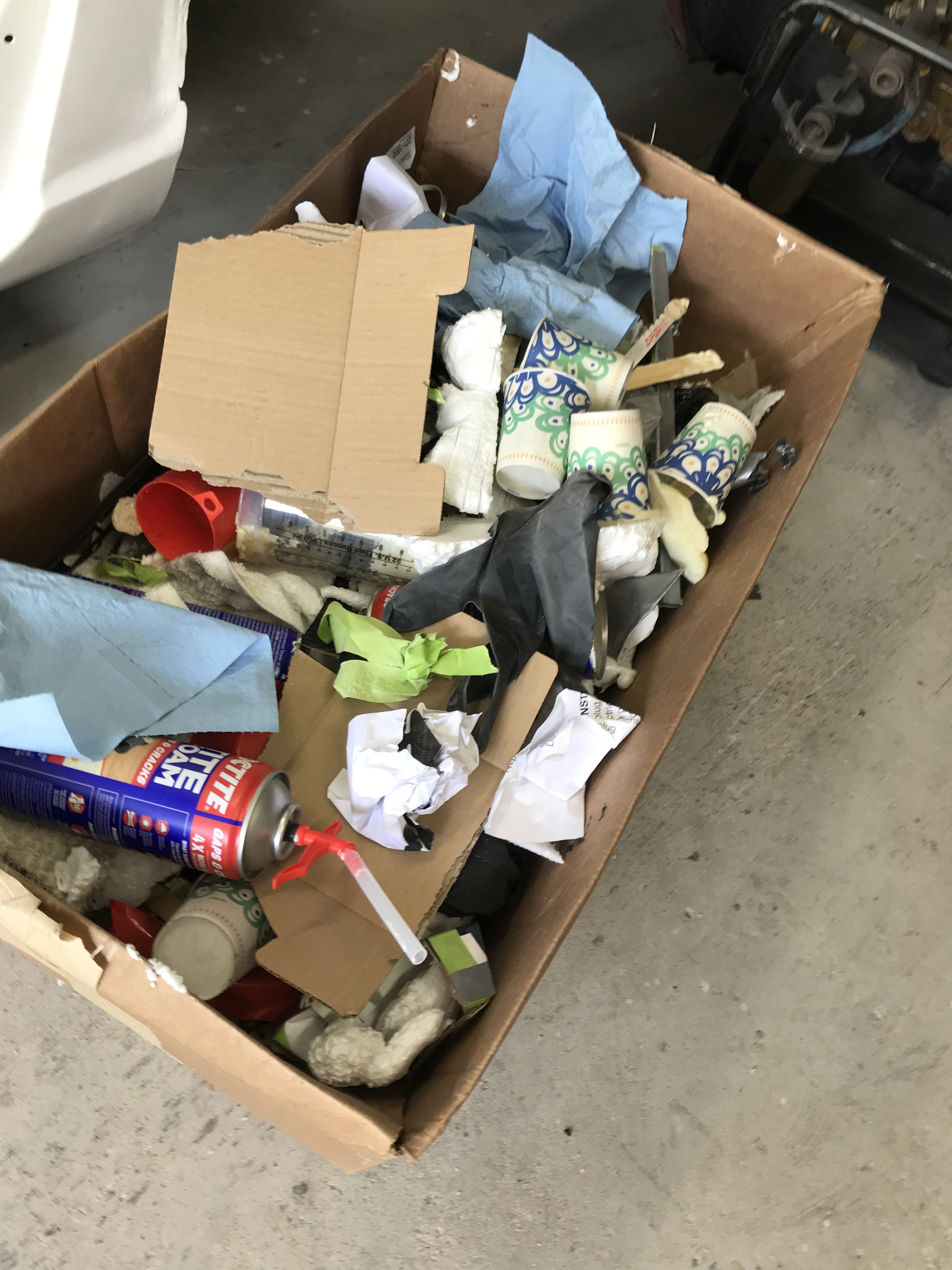

 After removal from mold and trimmed.
 Note-Its thinness and dfferent thickness of both longsides.

 Front view of Speedometer side of dash
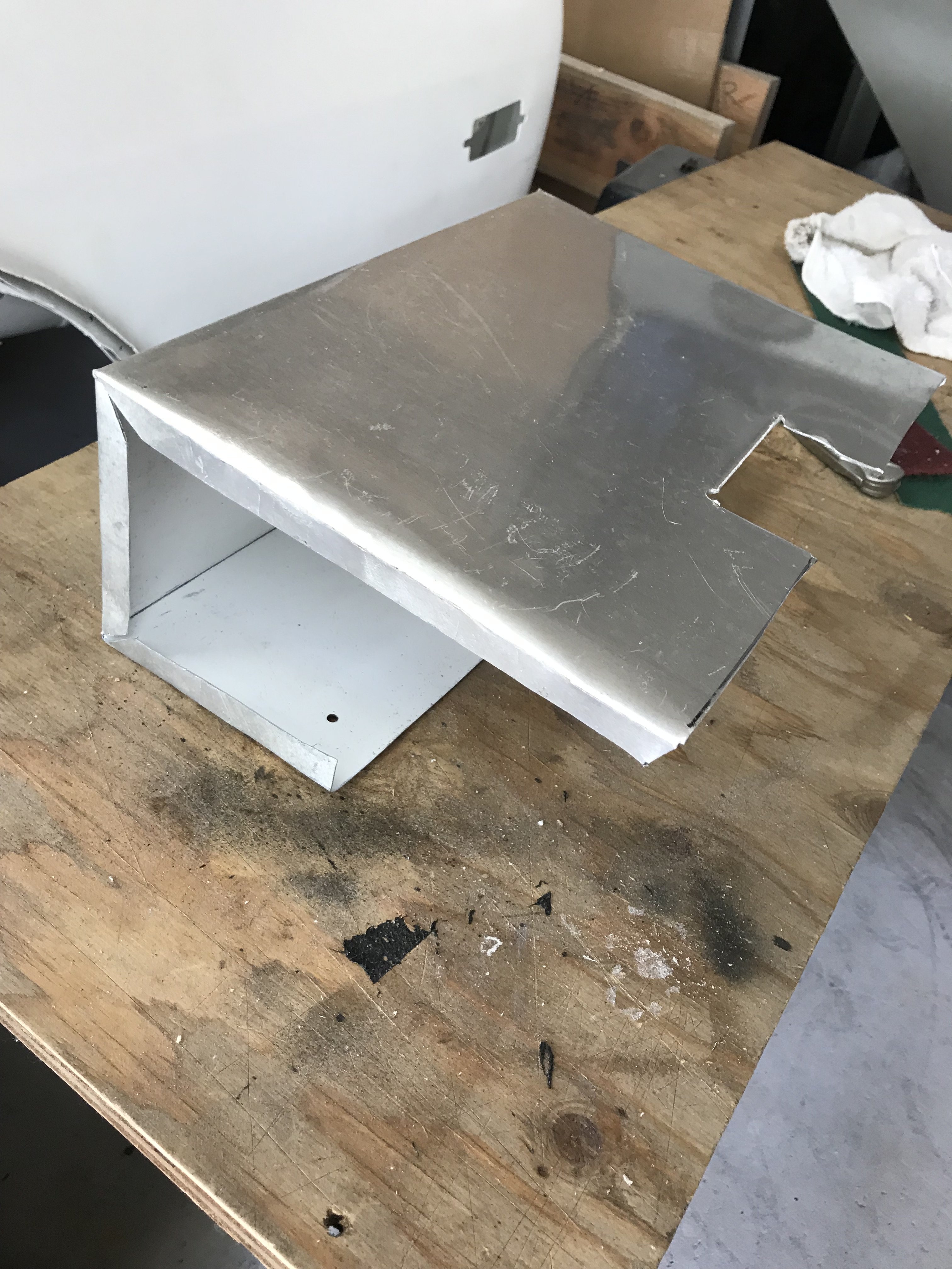
 The lower hole shows the foam coming through the dash.
.JPG.94fd61aa0cf3c7343703c74670003bfa.JPG) Inside section being epoxied together using vise grips.
Inside section being epoxied together using vise grips..JPG.d7956ab6d6a023516f053fc106b36ff3.JPG)
.JPG.b3b5070e229229ee4702feb133ad71de.JPG) Check gap and height alignment
Check gap and height alignment .JPG.1c73e9876bf0e571321b5574536a4e48.JPG)
.JPG.822ece04273d76821ebe42d4559d462e.JPG)
 Note-Allow time for foam to expand
.JPG.e235837c63630e5c6f6edde208473f13.JPG)
 Looks like a snow blizzard
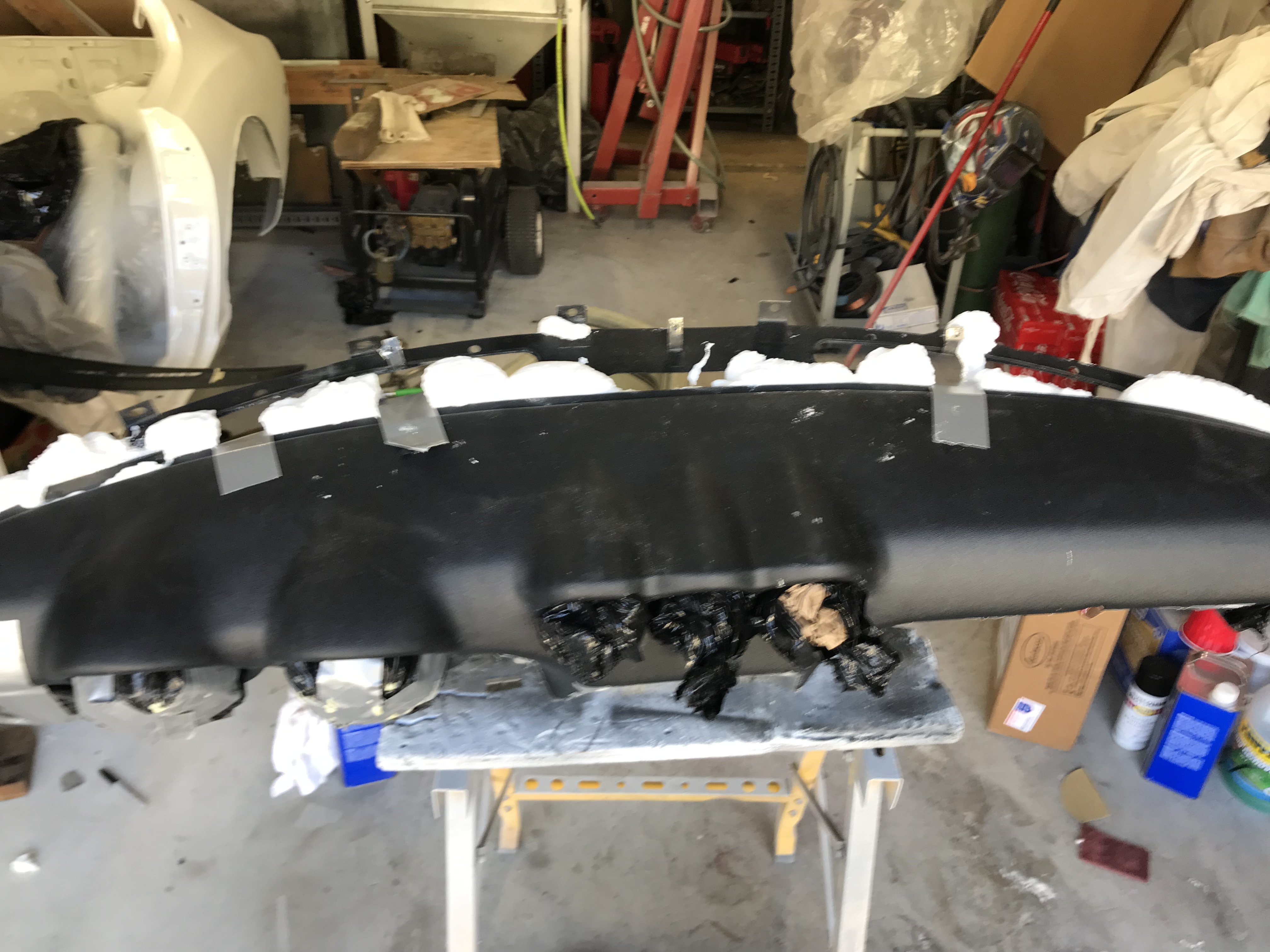 Top view of dash
.JPG.85ec9589dc6cc344ef9cd3661f056cef.JPG) Note-Huge cracks through out the dash board
Note-Huge cracks through out the dash board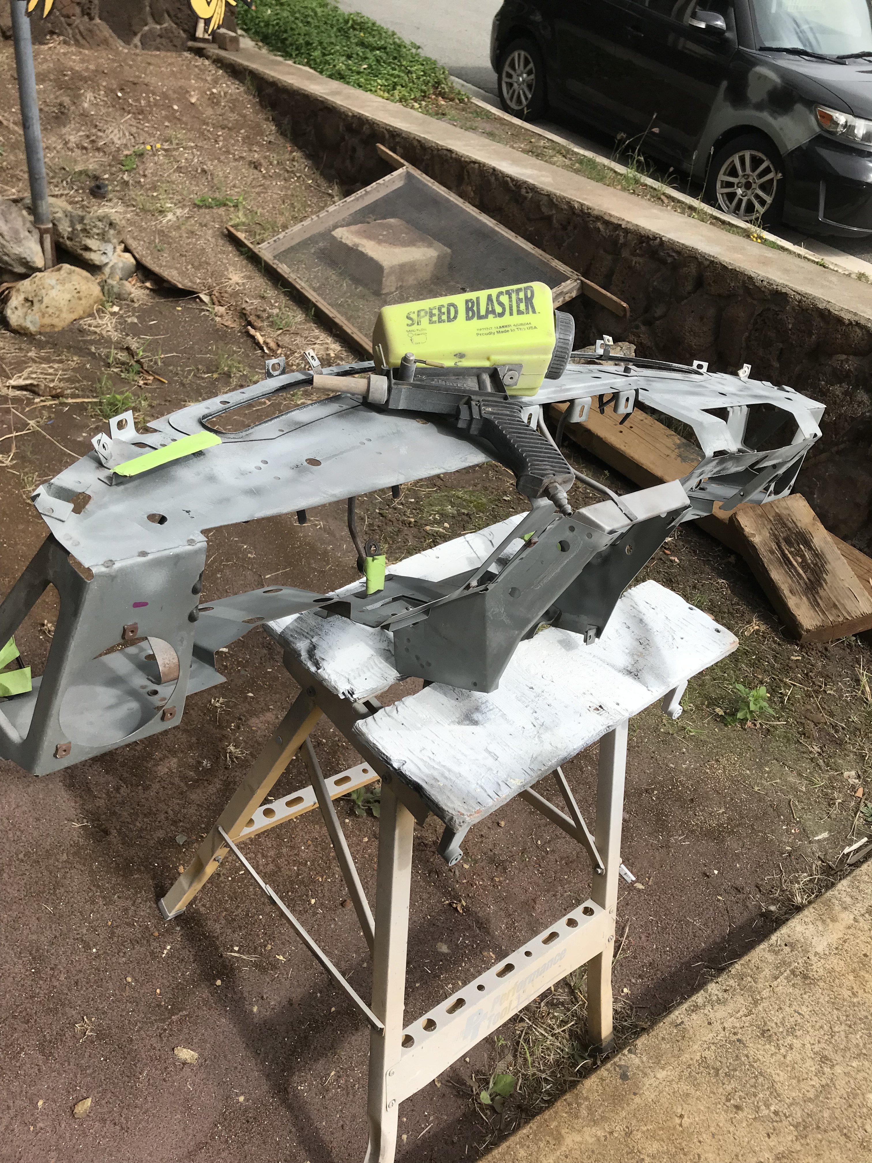 My Speed Blaster does a good blasting job on objects to bigger to fit in my sandblasting cabinet.
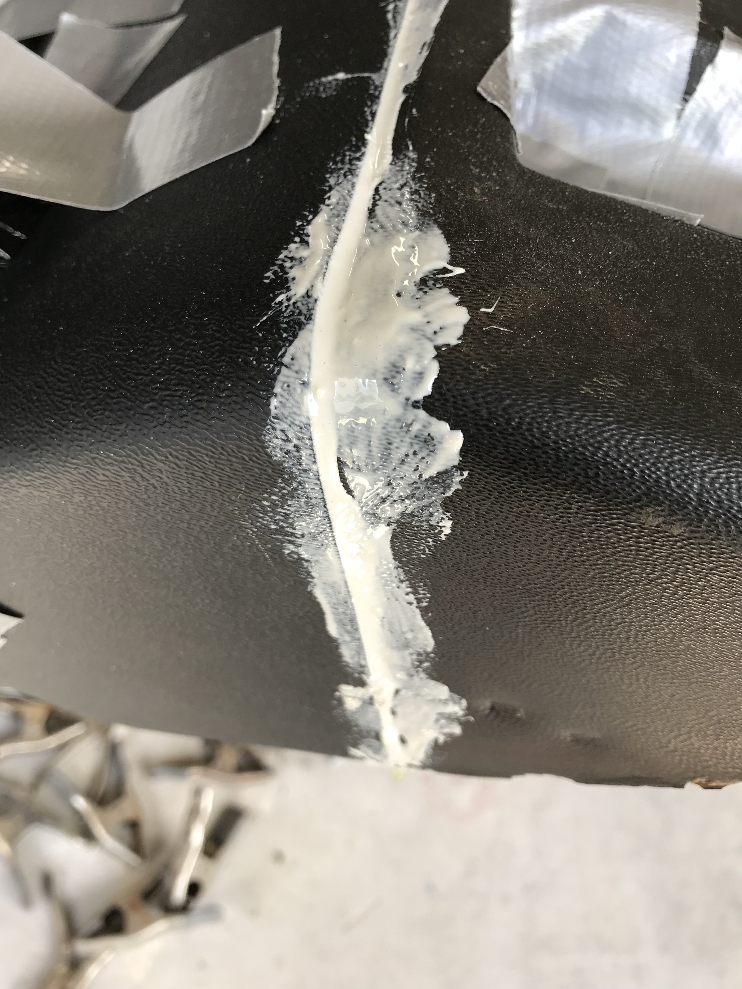 This corner section was sectioned off the original dash then epoxied to the replacement cap.
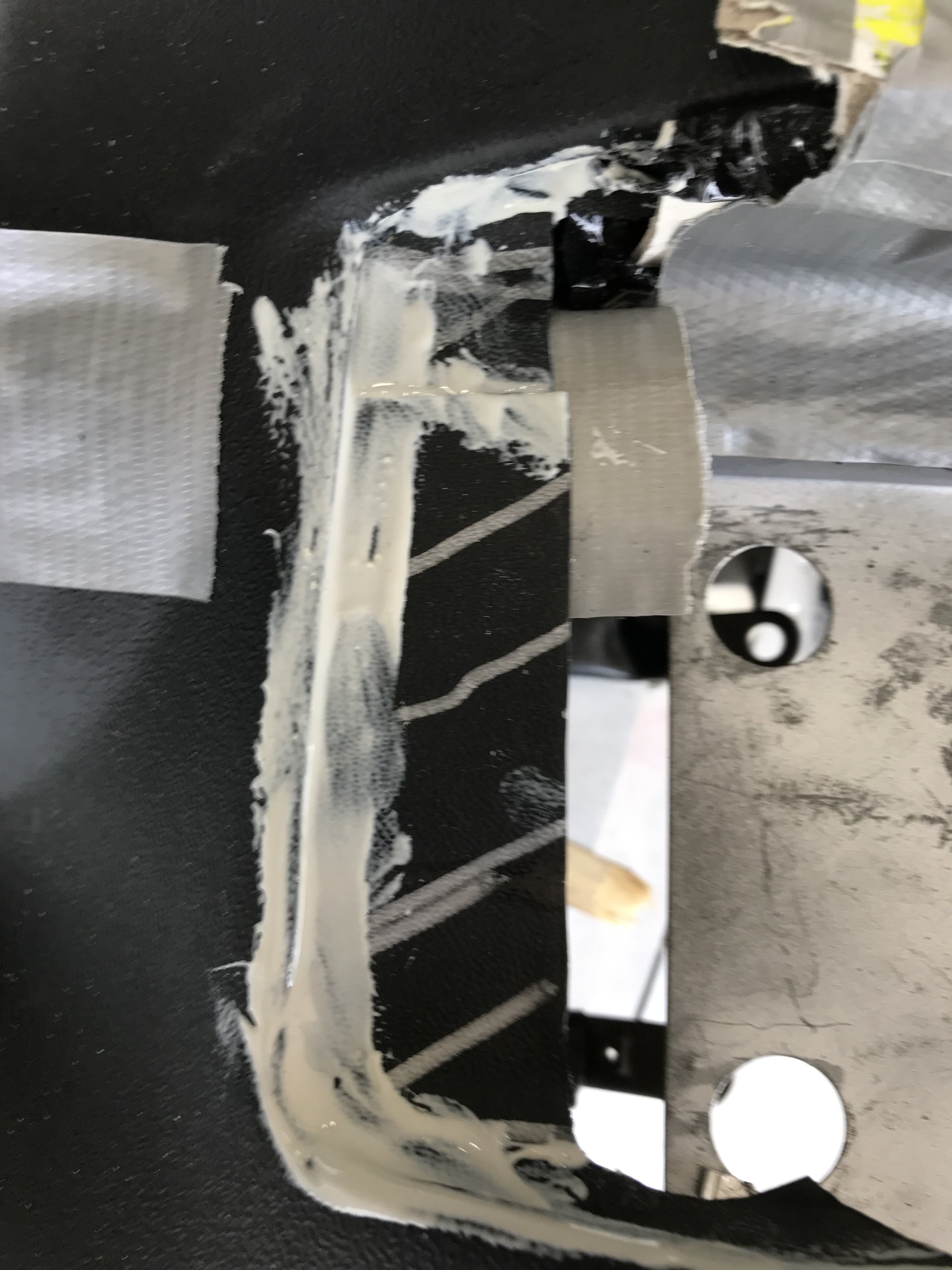
 Note=Black sheeting inside of the mold
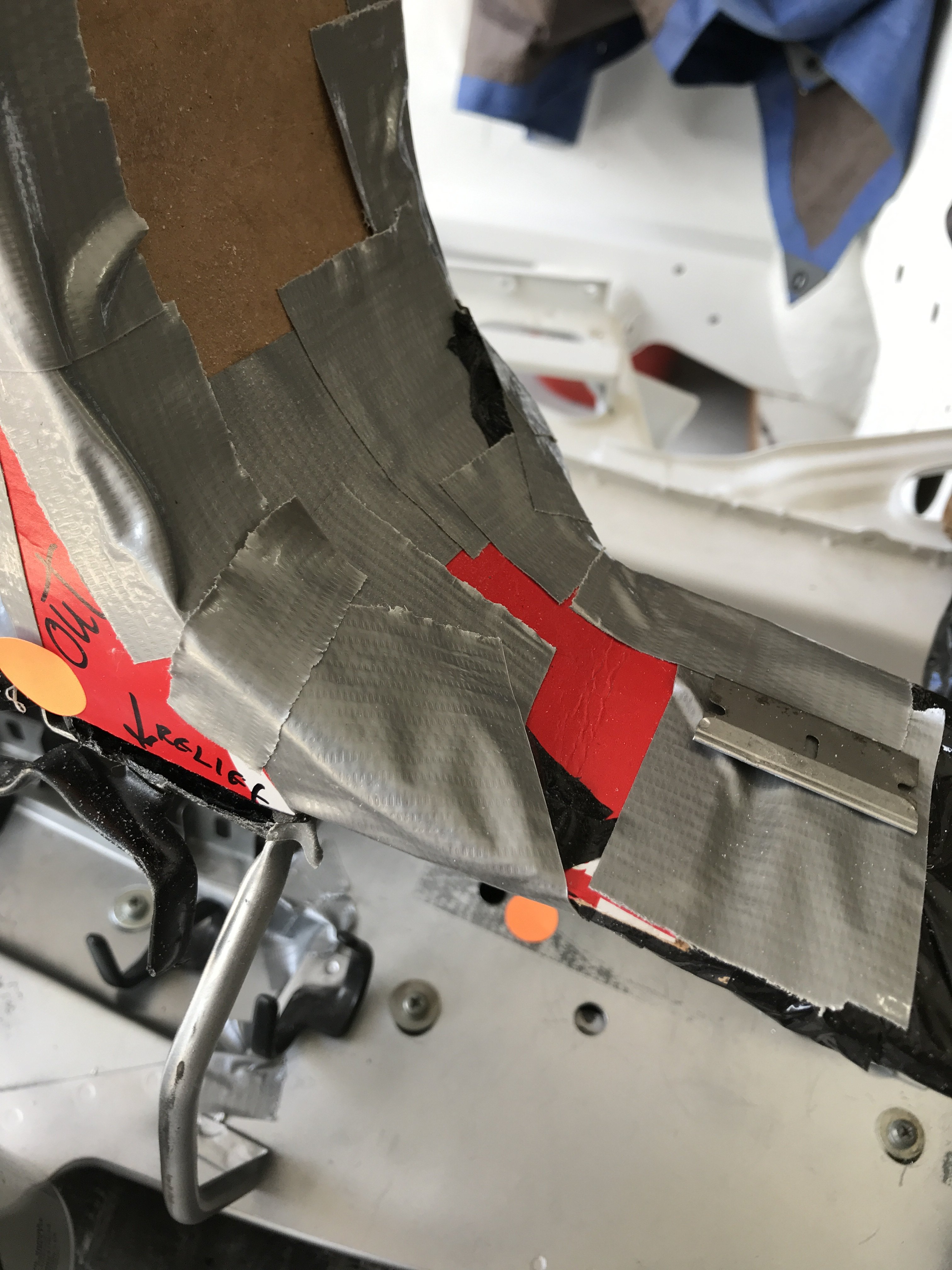 A
A.JPG.622bfb063092d8a16e9c212b5f009e6e.JPG)
.JPG.5687ff78f6b49b88400464bd404e1eb6.JPG) This view shows the mold attached to the replacement dash cap with duct tape.
This view shows the mold attached to the replacement dash cap with duct tape. This pic of the Right side lower section of the dash
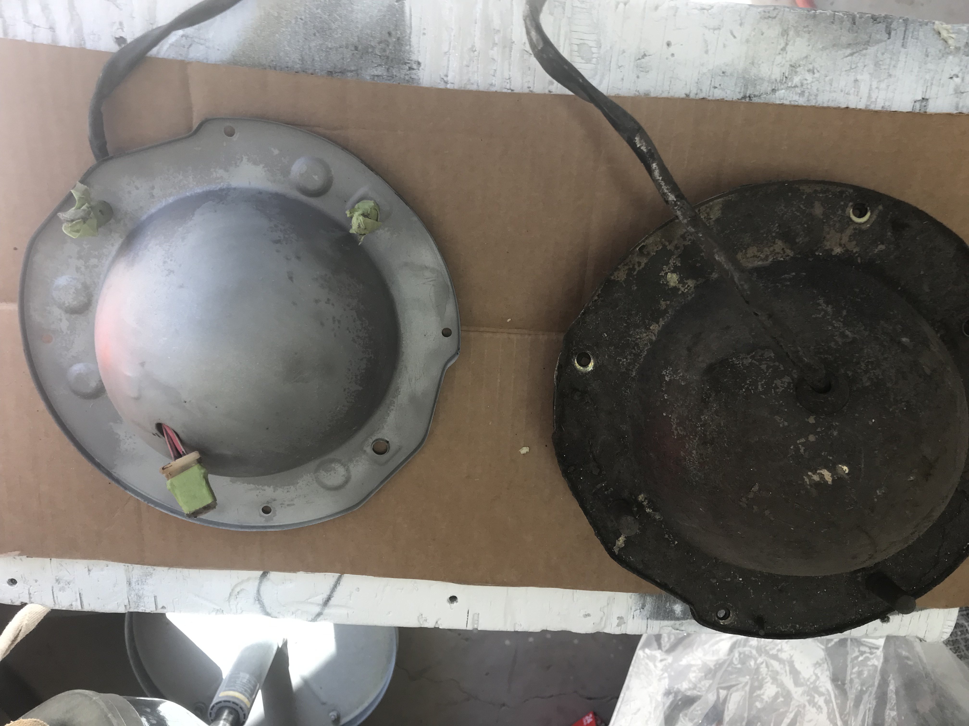
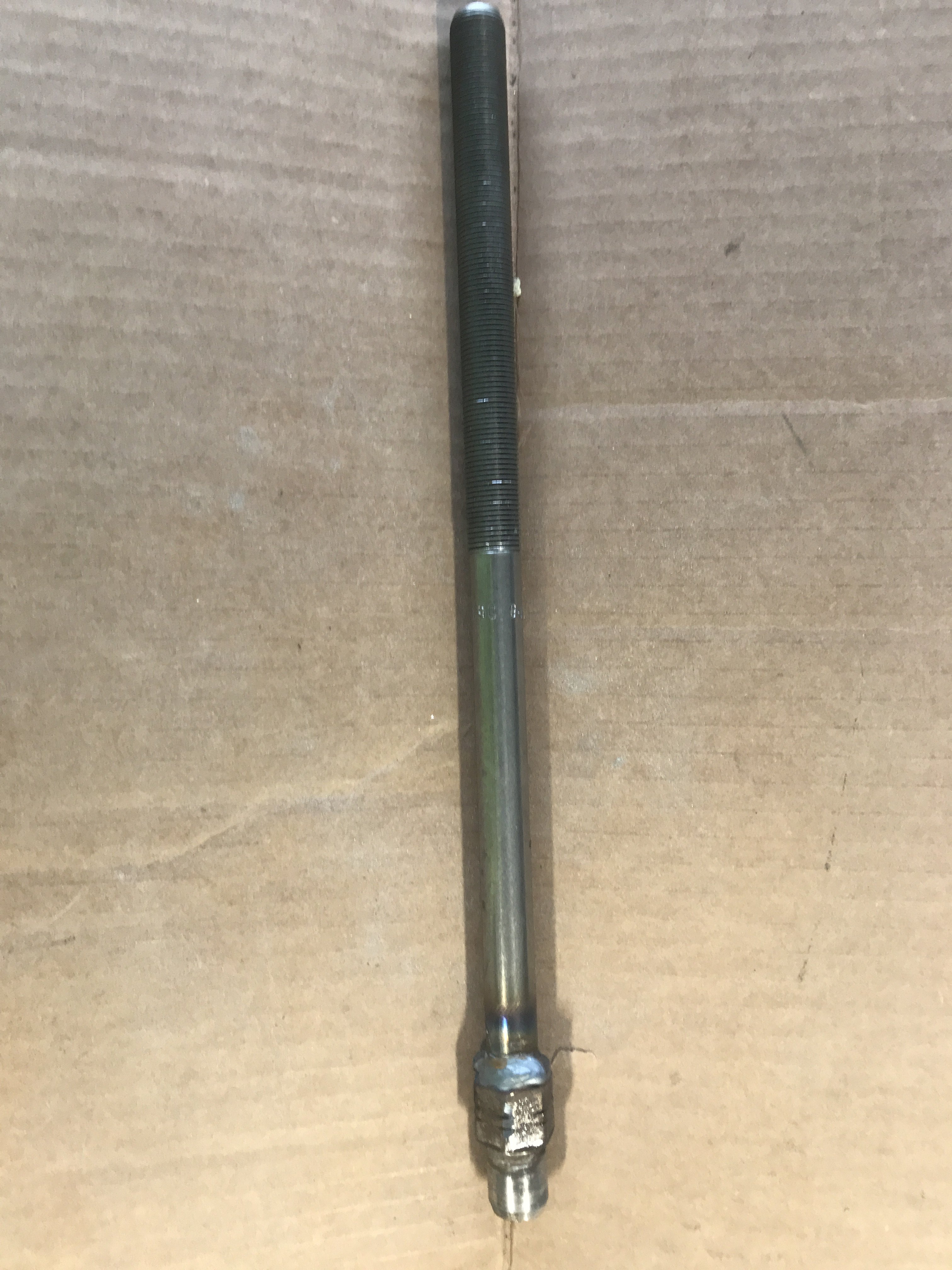 total view of 14" pulling screw
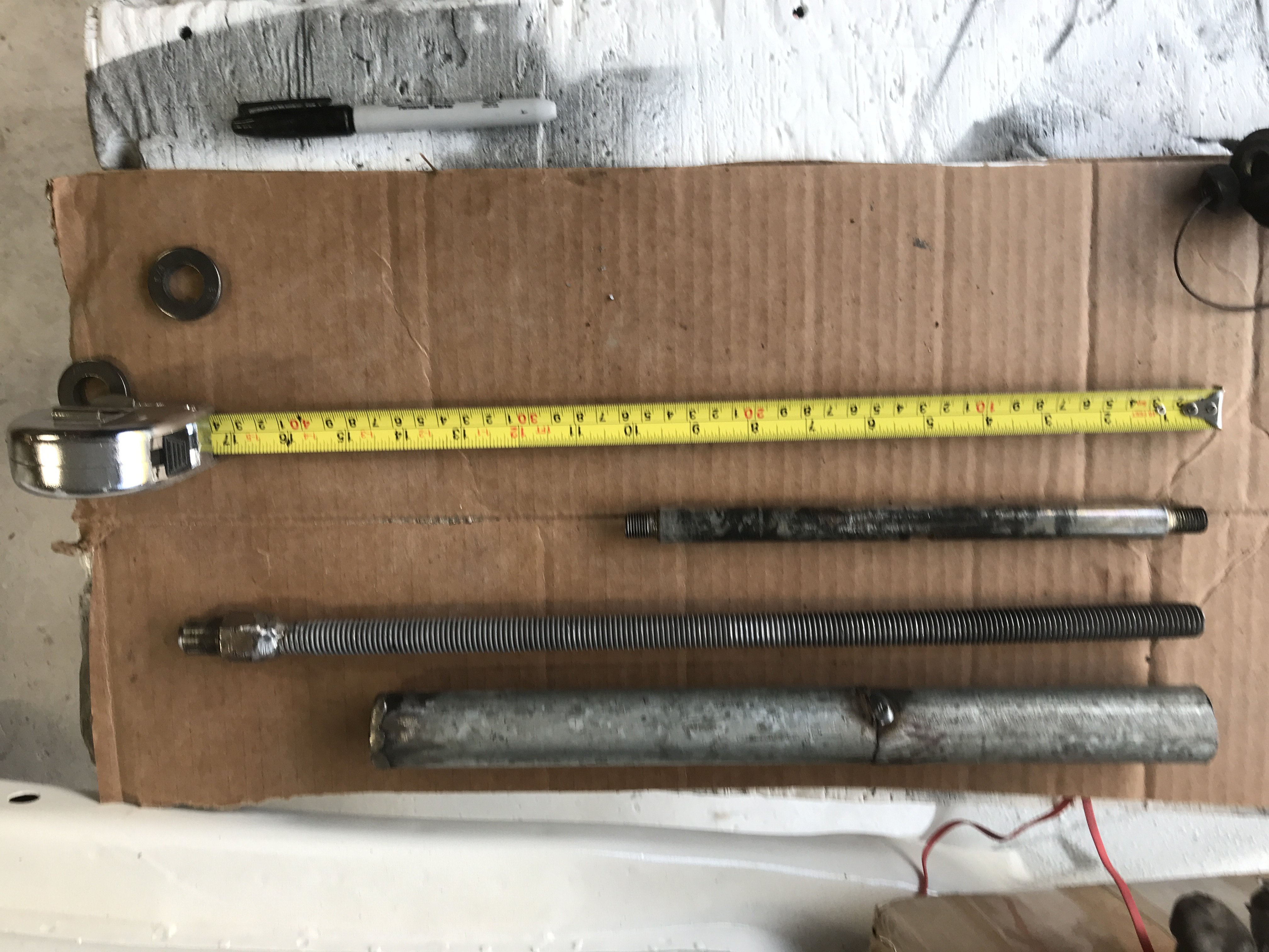

 used 2"x 6" planks and 3/4" plywood sheets to construct the dolly.
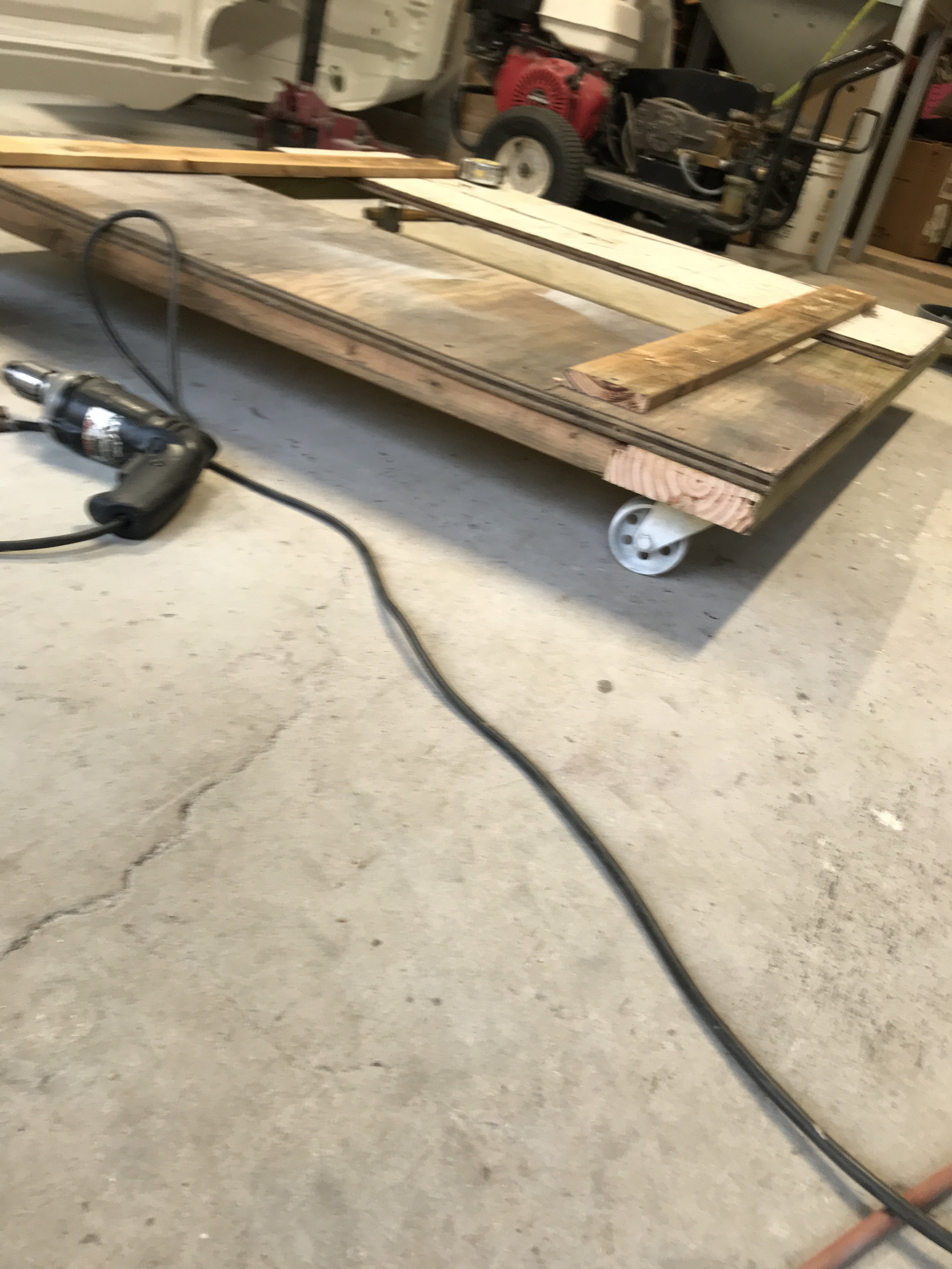 Two 1"x 3" wood strips were screwed to the top of the dolly to prevent the car from
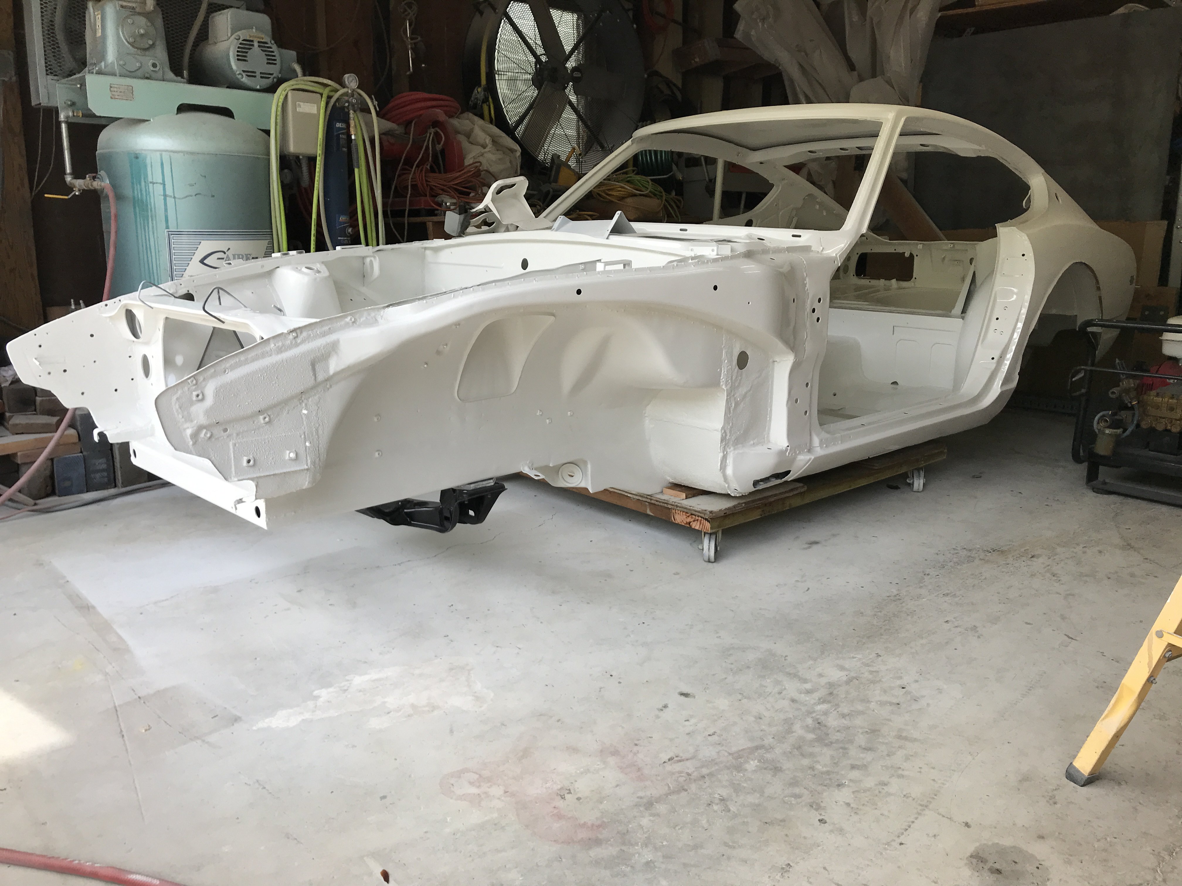
 The template was traced on to make a sheet metal patch
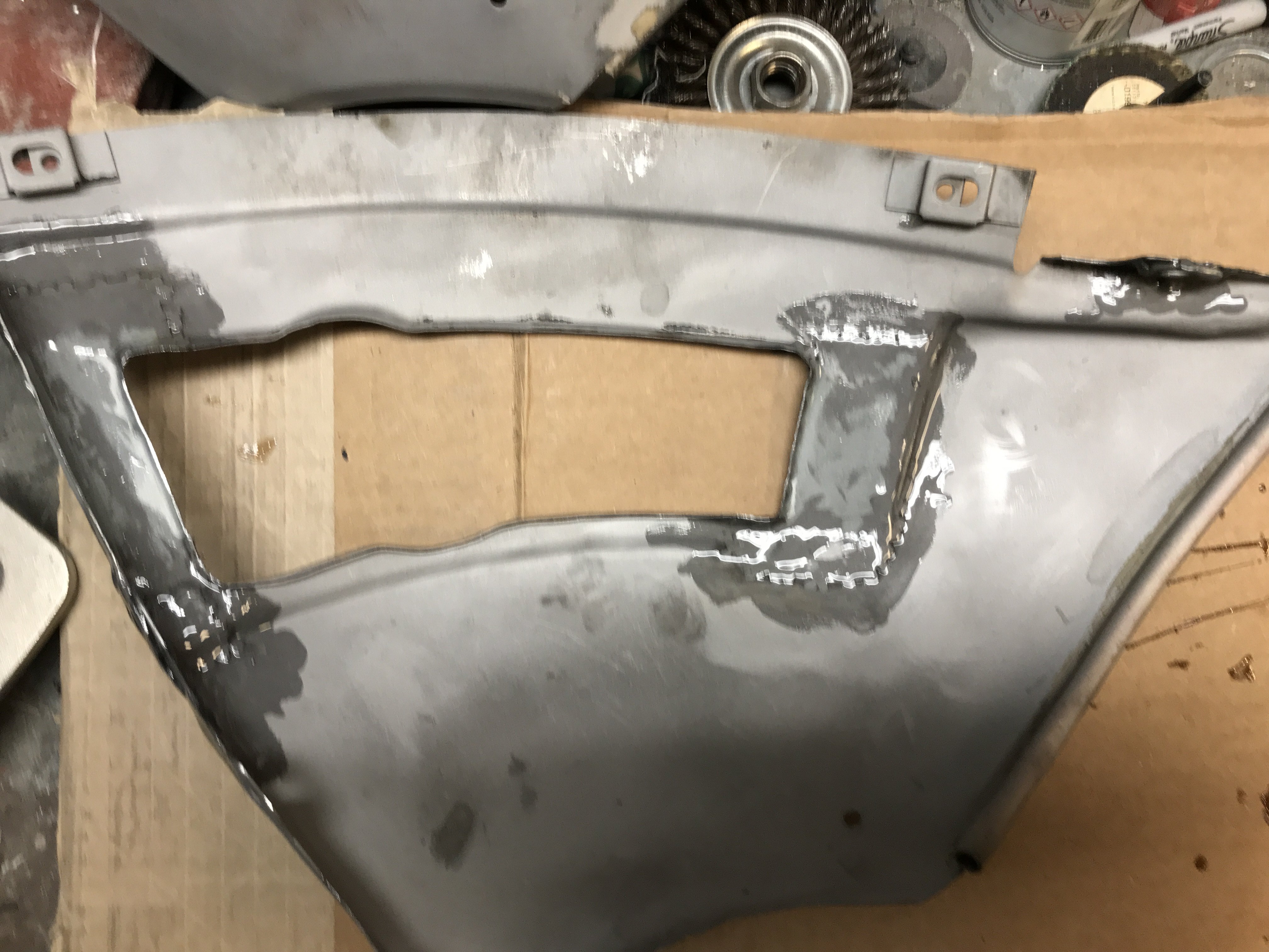 Inside view of the mig welds expoxied to
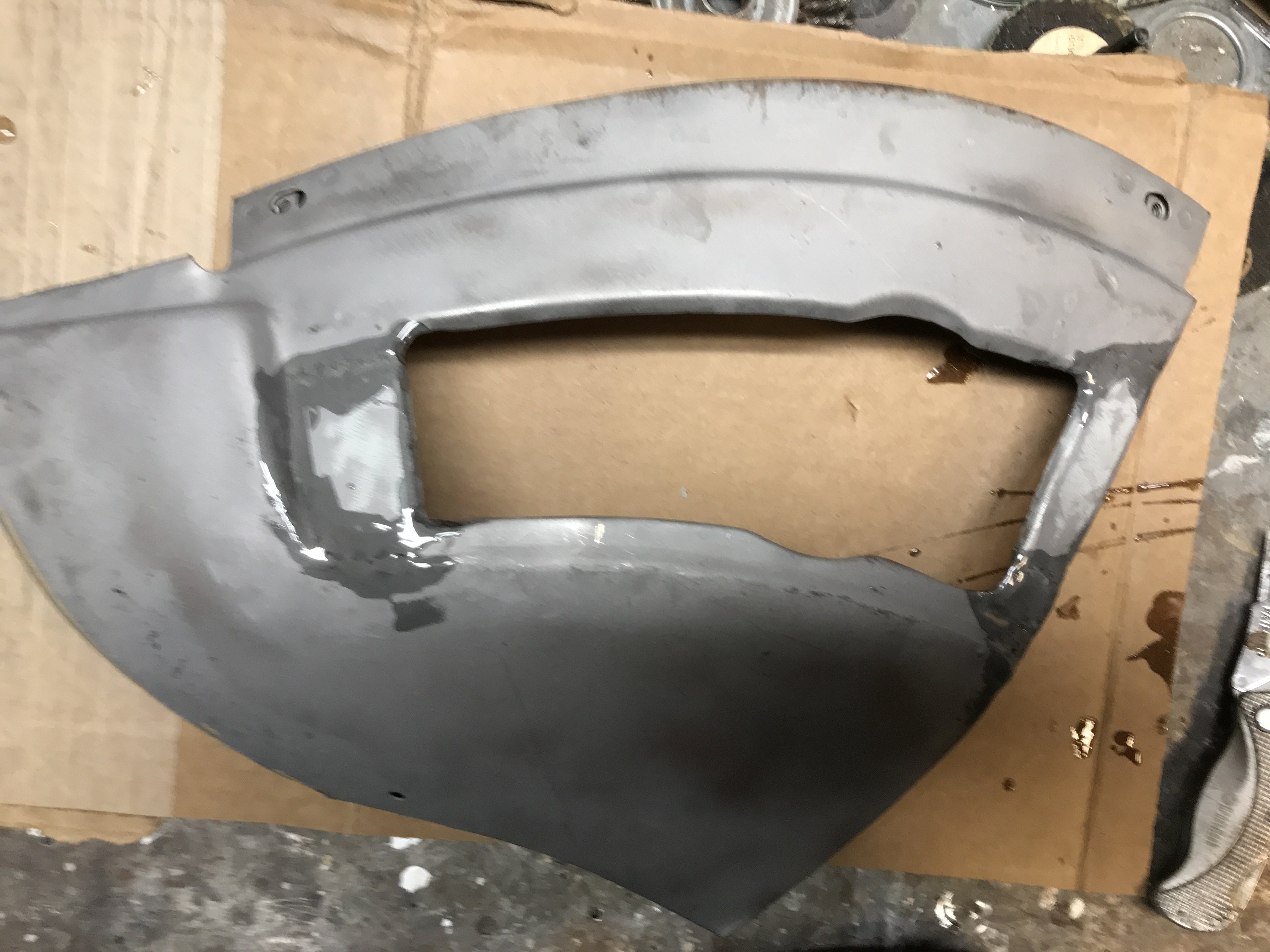 Outside view of bumper panel epoxied
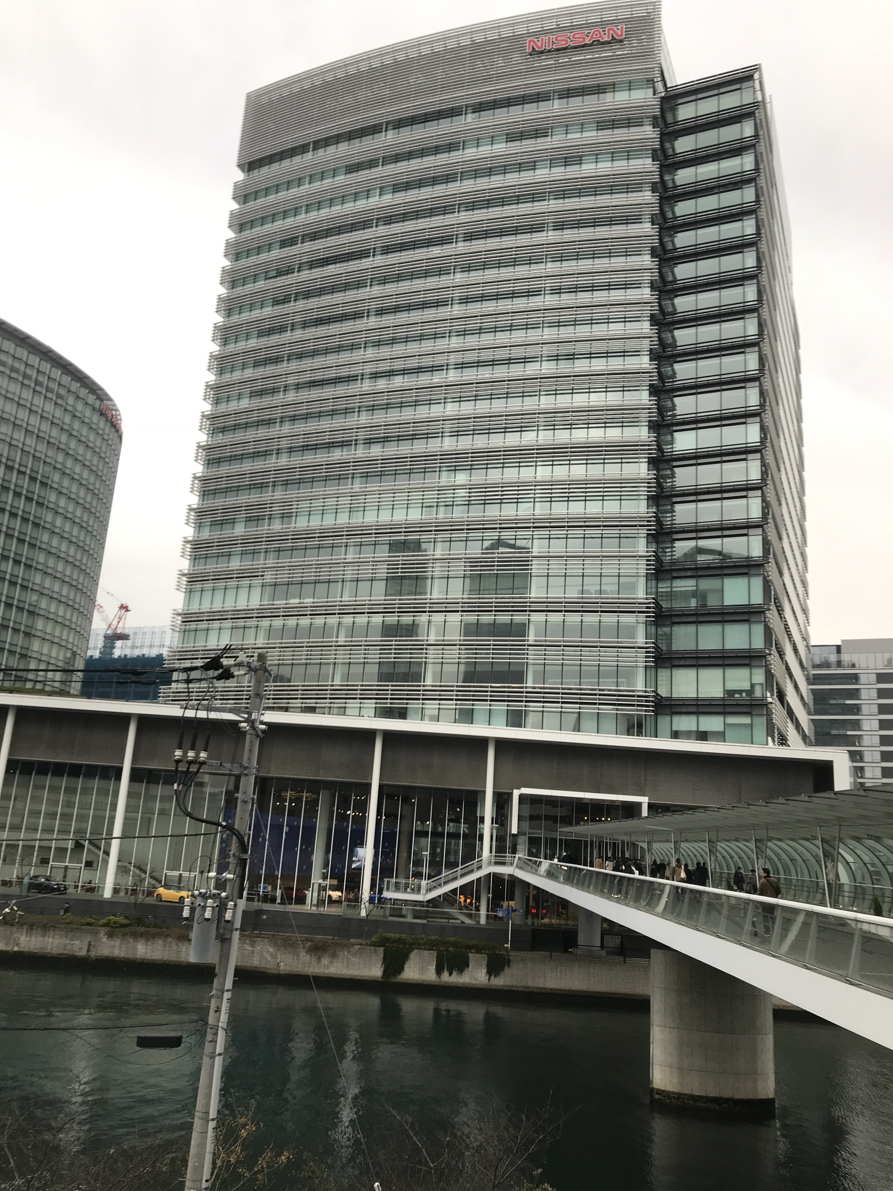

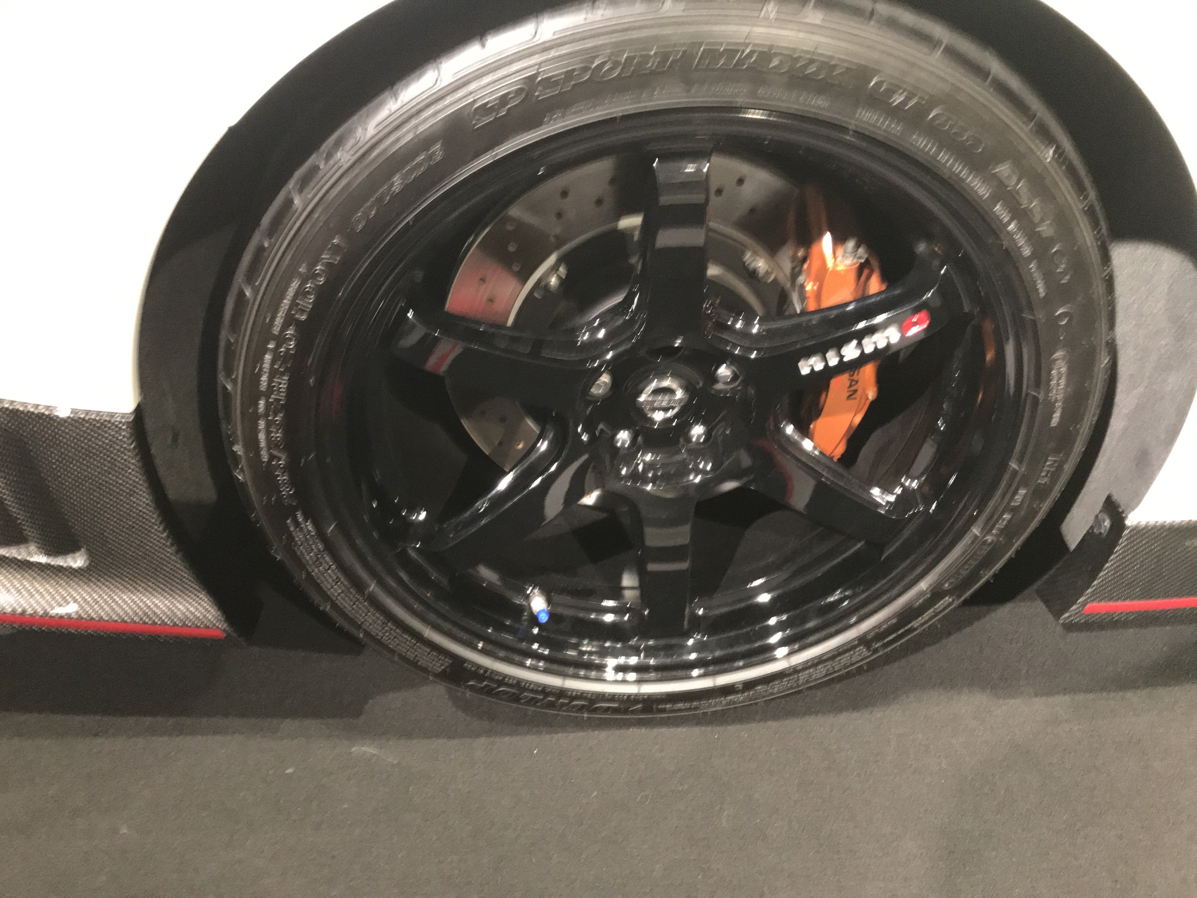 20"Forgered alloy wheels and huge brakes
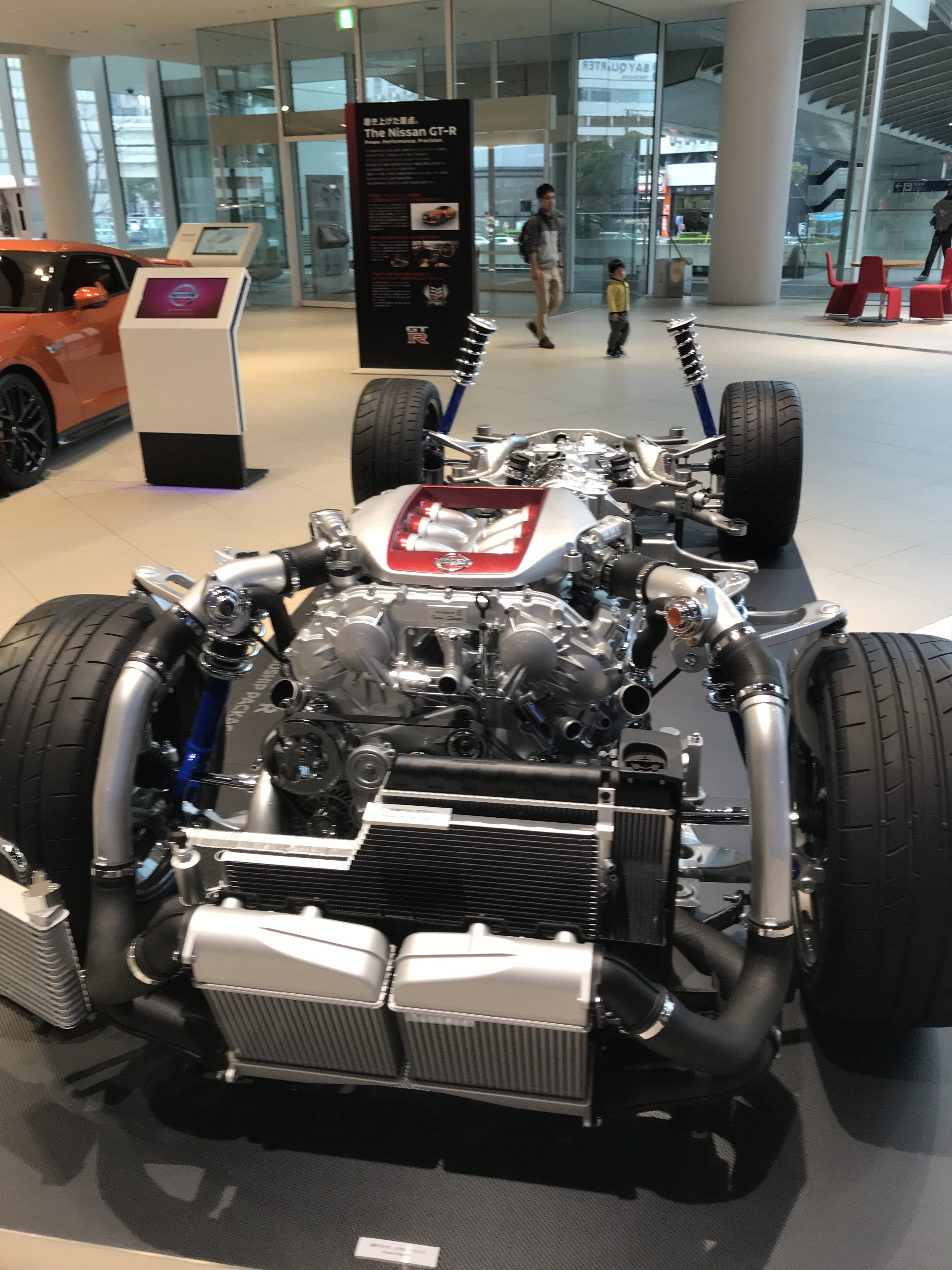 Twin cam 24 valve 3.8 Liter twin turbo
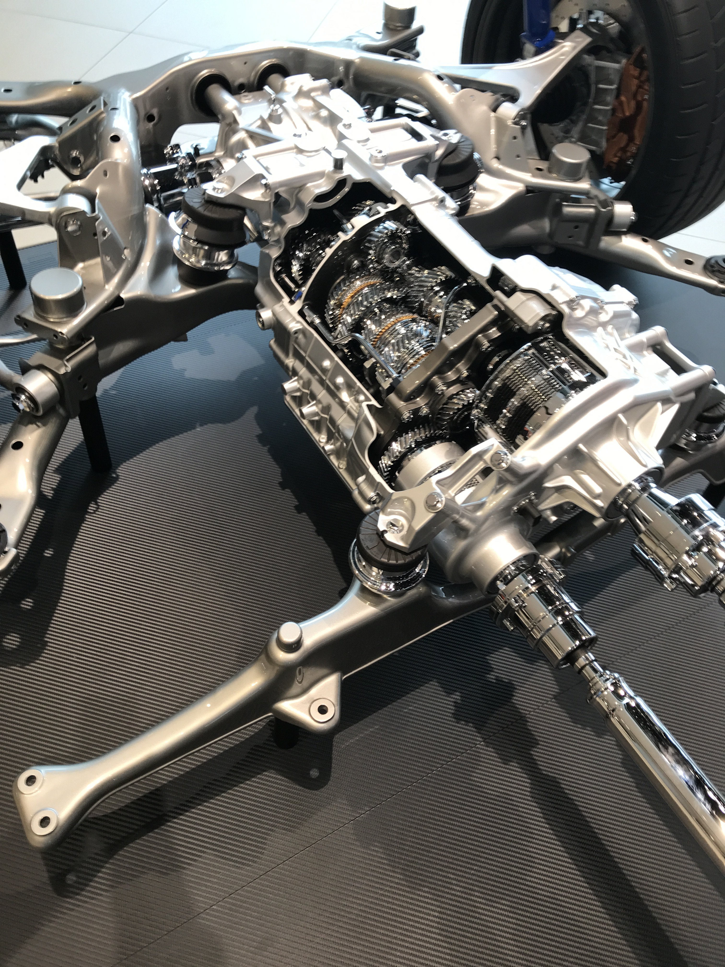 5 speed automatic transmission with all wheel drive
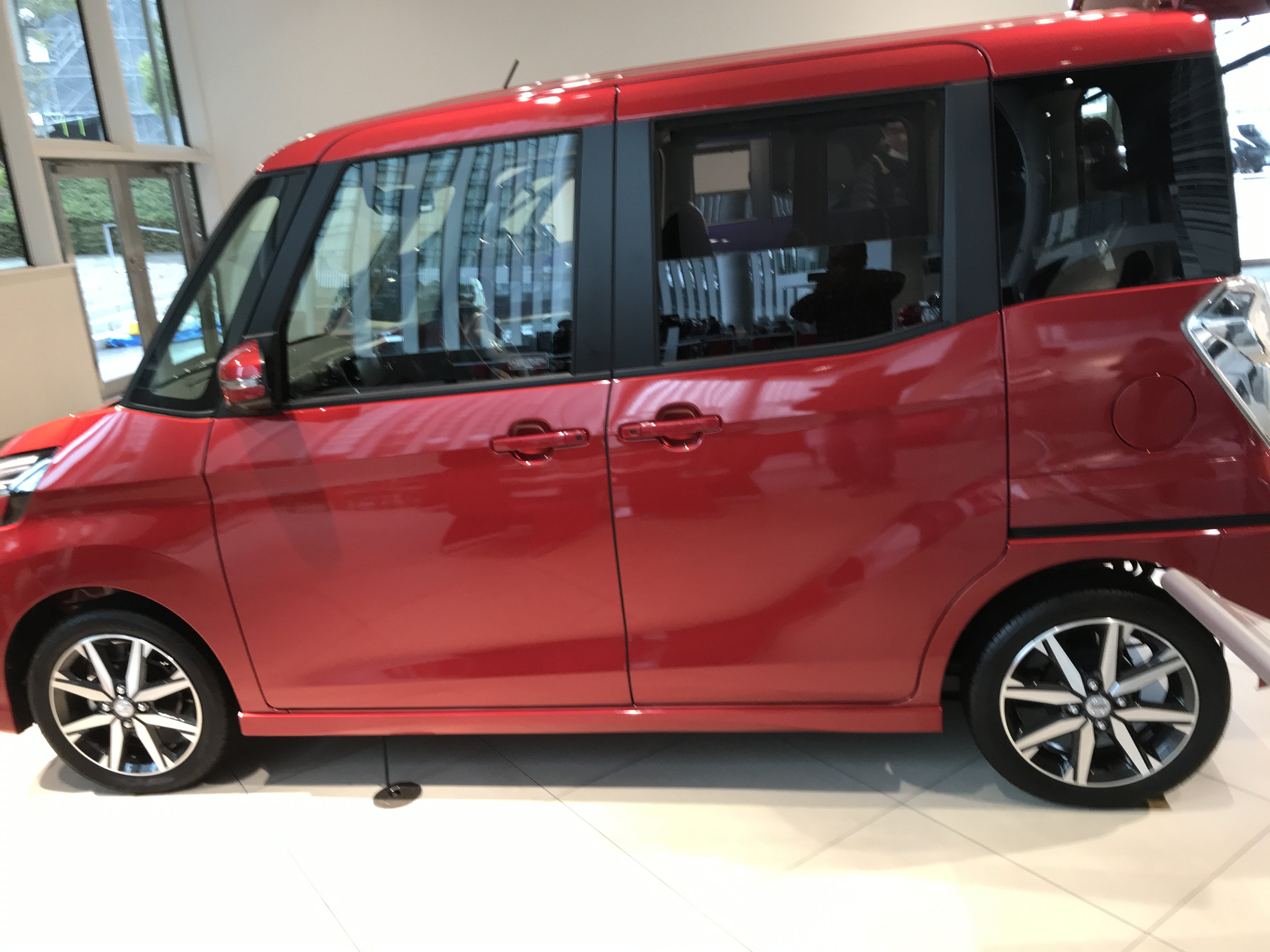
.JPG.06593d12488731afe919d5bcc6a86a40.JPG)


.JPG.35311fa40ed1e9613684a23095abd7d3.JPG) Save the casters to make HD dolly or another project
Save the casters to make HD dolly or another project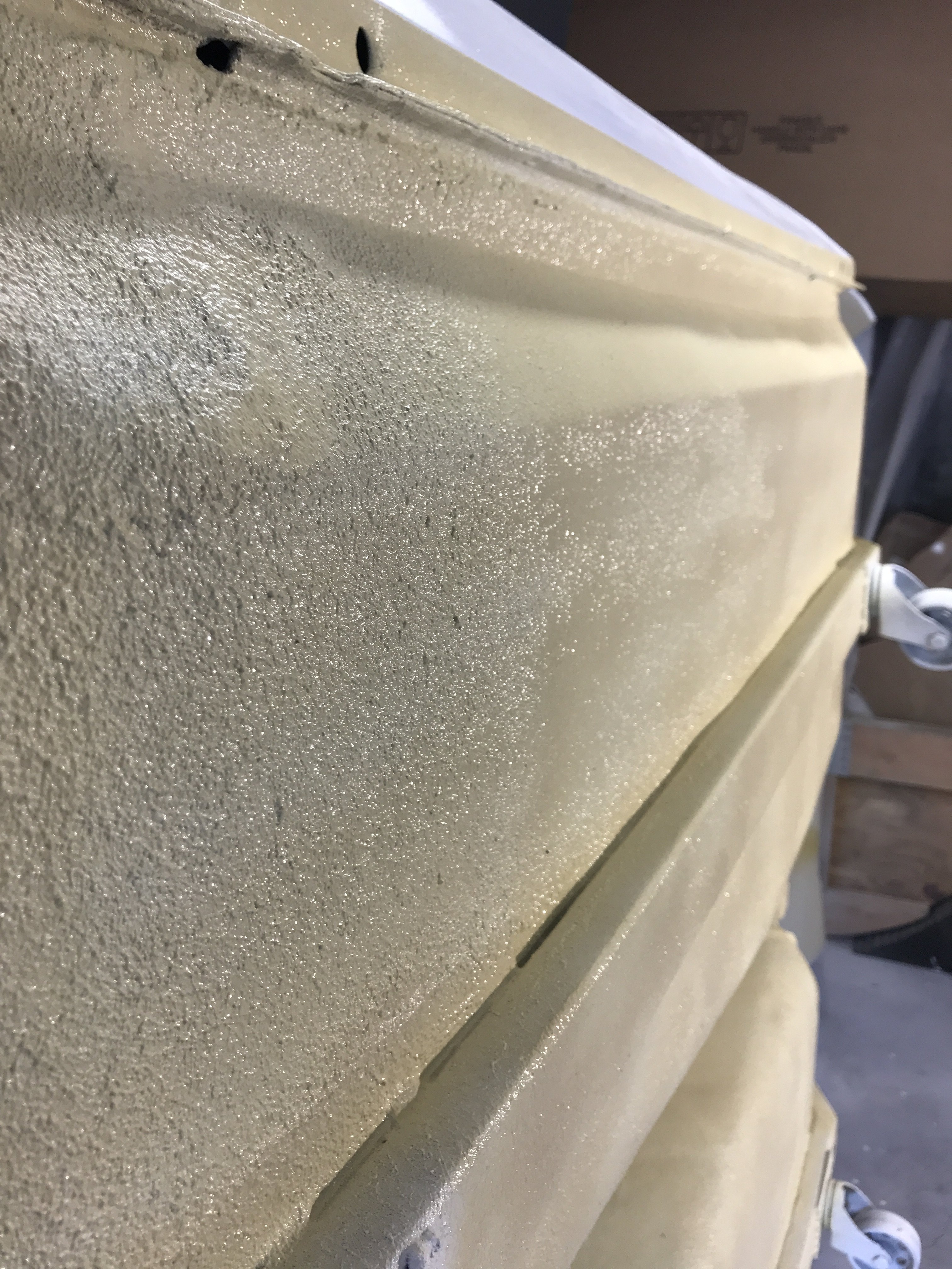
.JPG.0947244cda7a10bbb79026e5488d656c.JPG) Rear crossmember
Rear crossmember.JPG.2968128c130c07d9a95eeabc88e150d8.JPG)


 Right frame hole shows what the 1/2"rust proofing
  huge fender flares
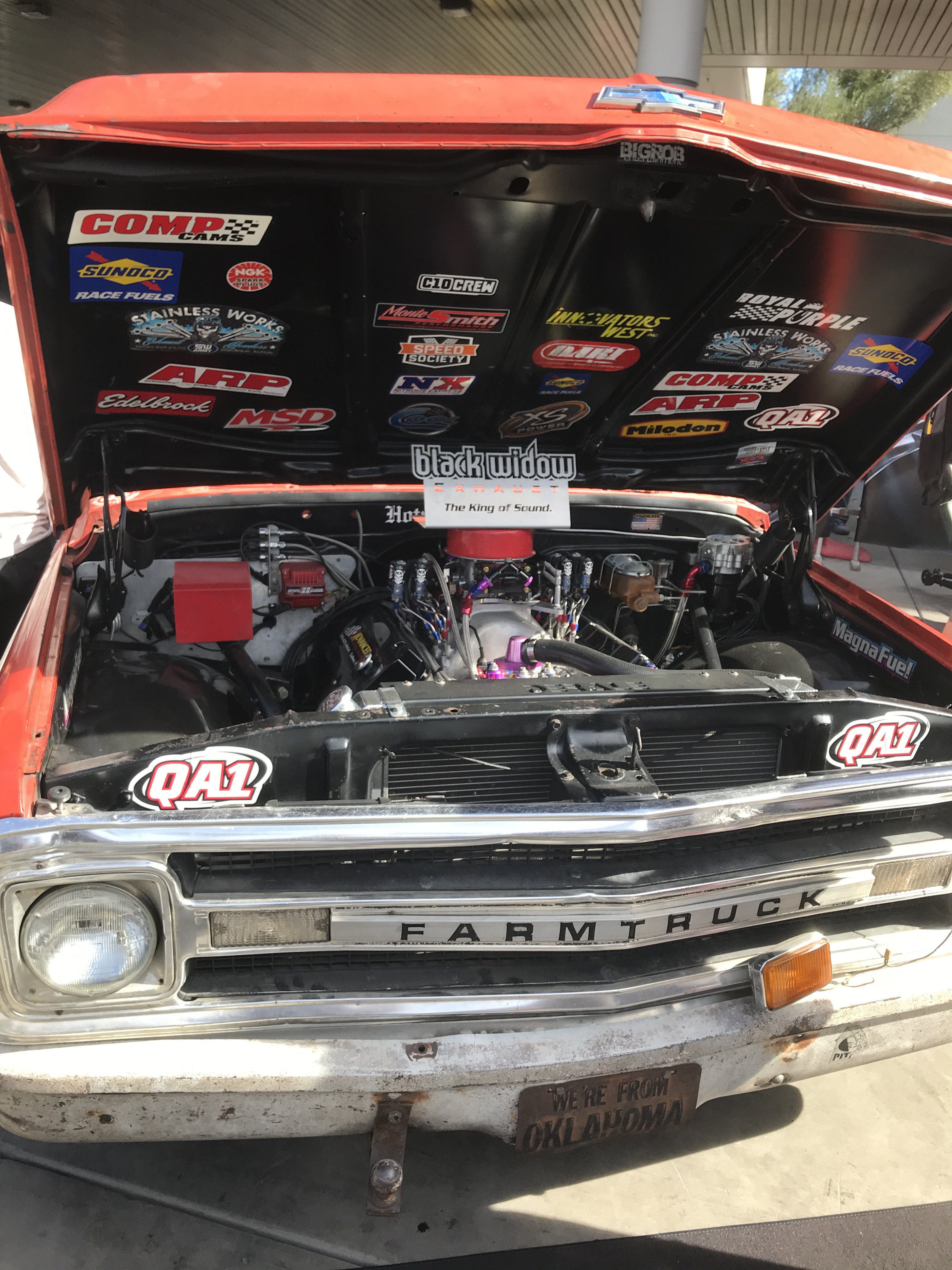


 700HP and 600 FTLB of Torque;
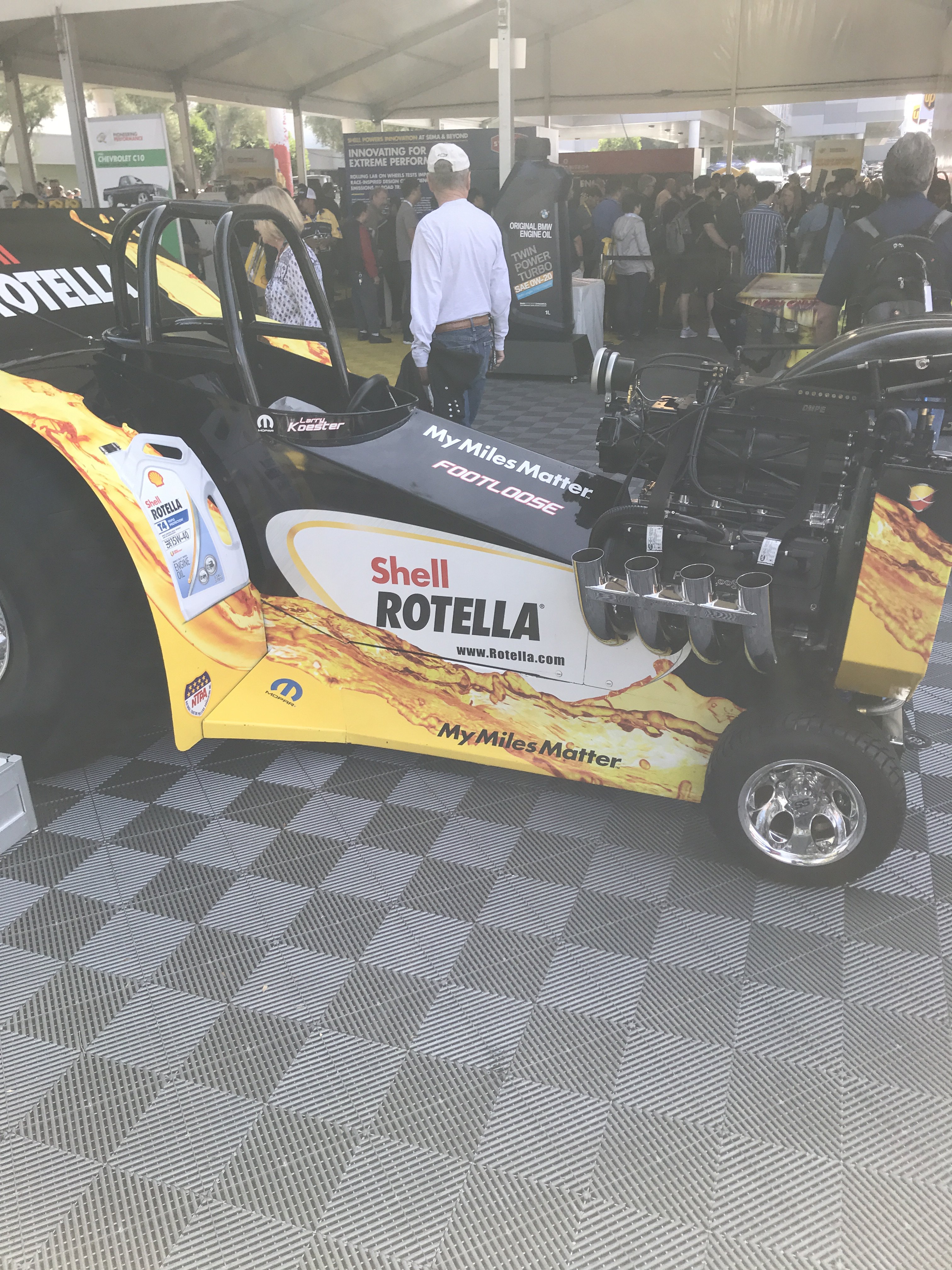


Heavy Duty frame rails and connectors
in Gen III & IV Chevy V8Z Tech Board
Posted · Edited by toolman
I found that turning my Toaster Oven on its side provided easier parts mounting.
I used a long cardboard box with the 2500watt infared light to cure long parts.
The top and side of the box was also covered with Foil.
The Hood Torsion Spring Rods were slightly longer than my Infrared oven. So the rods were cured on one side then flipped over to cure the other side.
The most difficult part of this powder coating job was trying to match the Chromate plating. To achieve this. I used Super Chrome as the base powder
coating. Translucent Gold powder would be used as the Top Coat. But there are about twenty different variants of the Gold color. There are also
many variables in the application of the Top Coat powder. The number of Top Coats applied over the base Super Chrome will make the color darker with
more coats. Preheating the part being coating aids in adhesion but changes the color slightly. The speed of powder spraying affects the color shade.
The spraying distance from part affects color especially with metallic colors. I made dozens of metal strips to test the various powder coatings.
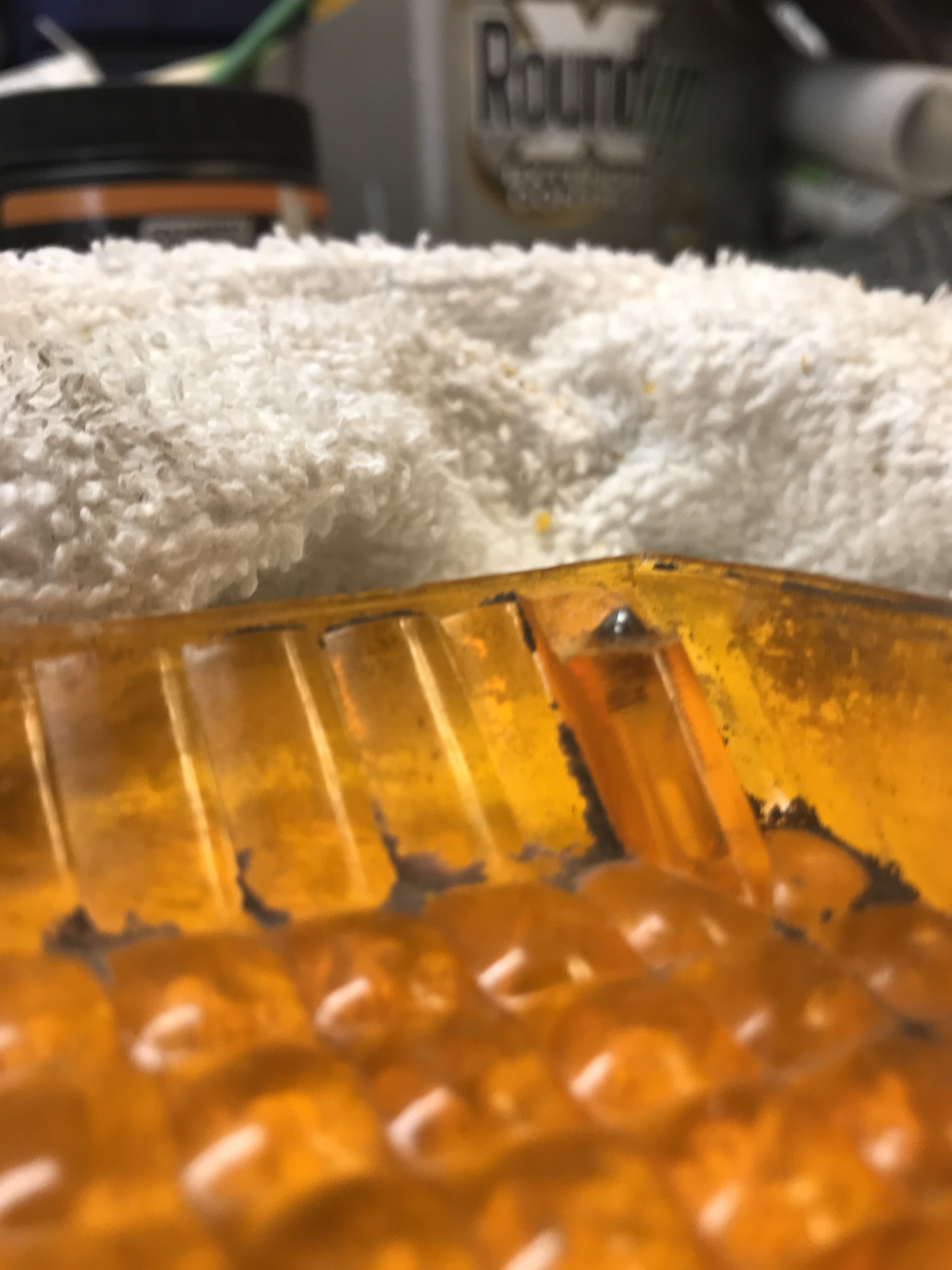
If you used the wrong color, you can strip the powder coating off with Kwik Strip New Paint Remover. This is not the old Aircraft Paint Remover with the toxic
fumes and really messy.
when coating wrinkles. Then, scrape off using a plastic spreader. Wear gloves and safety googles when stripping. I took my gloves to take this photo. A small
particle of stripper landed just above my glove and it burned like Hell!! The stripping process was faster than the old Aircraft Remover. Less Fumes and
a more "Dry" method.
After Top Coat Powder Coating, the hand Brake bracket looked that this:
The Head Light Housing and Buckets come out like this:
Hood Hinges
This effect was purposely done to match the Chromate plating as possible.
The cost of this Powder Coating of these parts: Eastwood Powder Coating Gun and accessories was$150 , SuperChrome powder was
$25, Translucent Gold Powder was $27. Kwik Stripper was $12.00, 2500watt Infared light(used) costs $50 =$264 Total I intend on
power coating a lot more parts( like crossmember,lower control arms, coil springs, etc. I would recommend powder coating for any
restoration project.