

RTz
-
Posts
2943 -
Joined
-
Last visited
-
Days Won
23
Content Type
Profiles
Forums
Blogs
Events
Gallery
Downloads
Store
Posts posted by RTz
-
-
Do they still have the memory chip??? you can have several differnt tunes by just pulling out one card and plugging in another.
That ended with V4. V500 has two switchable mapping systems, built in.
I might know where there is a well cared for V4+ system for sale, and the 'cards' are still available. Want me to check on it?
-
I want something that will plug directly into the rb26 stock engine harness and control everything and have inputs for nitrous, control boost ect ect.
Wolf3D can fill that bill.
also needs to datalog.Technically, Wolf datalogs. However, I'm not crazy about it. A bit clunky in my opinion. To Wolf's credit, it's *always* logging... you capture data 30 seconds before you hit "record".
-
That seems to be the trend for websites lately. Make them really cool looking. Cool animations, sounds when you roll over buttons, and of course, a royal pain in the ass to use.
Websites? It seems like most every consumer product produced & advertised has become a bad circus act.
-
That is the generation that is retarded and as such likes two things... Shiny things, and anything chemically treated (the mall, Sorority girls, McDonalds, Bud Light, basically anything that is bad)
...kind of like fish really.
You're killing me

-
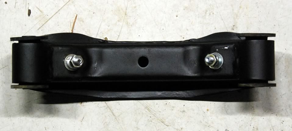
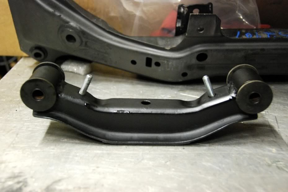
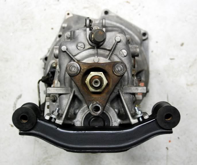
With the drivetrain sitting in the '77, it was clear the tranny needed to sit as high as possible. For giggles, I stuffed a stock Datsun mount under the trans, and found it to be a near perfect fit. Only needing to trim some of the flange off the front side, re-weld the flange at the cut, drill two holes for the fasteners, and a little massaging of the surrounding bolt hole area with a press (to provide enough flat area for the bottom washers to rest against). Took longer to clean and paint than to modify...
This location puts the tranny about as high as practical, with the height of the output shaft about 1/8" lower than stock, and the motor longitudinally within an 1/8" of of the pictures above. If the rest of the swap was this easy, I'd have it done in a couple of weeks
-
Here's a silly example...
A. Assume no tire slip.
B. Assume same size, non-vented brake rotors front and rear. And they weigh 50lbs each
C. Assume no brake pads (keeping it simple for this example)
Run the car at a dragstrip, with the front rotors removed, but the rears installed. Run the car again with the front rotors installed, but the rears removed. What do you get? The same exact timeslip.
Put the same car on a static dyno, same two scenarios, and the HP numbers will show the exactly same regardless of where the rotors are mounted, just like the dragstrip confirmed. Just like the real world.
Put the same car on an inertia dyno, same two scenarios, and the HP numbers will show higher with the rotors on the front, and lower when they are installed on the back. Funny, since the car ran the same 1/4 mile time.
The point is, inertia dyno's can be deceptive, especially to those young men that think installing a lighter wheel produces more power because the inertia dyno said so. They gained acceleration, not power. They reduced inertial losses, not drivetrain losses.
-
Another thing is what MAG58 said about light weight components (CF drive shaft) not making a difference in power output is plainly incorrect. A drive shaft has to be accelerated just like the gears in the transmission. It has mass and a heavier one will be harder to accelerate and give more drive-train power loss.
MAG is plainly correct. Put your car on a static dyno and measure power at a specific RPM. No driveshaft material will change that number.
The inertia of a wheels, brake rotors, driveshaft, flywheel, etc, etc, will influence acceleration, but not power. They are not part of a drivetrain loss calculation. Friction is.
-
Just curious if I should check sequencing of the injectors or does it not matter? Currently it's set to;
Inj1 PO - 5,3,1,4,0,2 and pulse skip are all 5.
It doesn't matter right now. You're car will run fine on any fueling order. Later, when you put the car on a dyno, you can bump those numbers up or down and select the sequence for best power. It will normally be a modest gain... too small to feel in most cases. If the sequence was grossly out, you'll likely see a slight improvement in idle quality, as well.
-
Or R if it's a 260z.
Now that one I knew... just forgot
-
Also GHLS30 for the 2+2.
I learn something new every day
-
To my knowledge, all S30 VIN's begin with HS30 or HLS30 (L = left hand drive).
-
I can confirm, this is how the coils are wired up..
A12 Black/Brown wire - channel 1 (coil 6-1)
A13 Black/Red wire - channel 2 (coil 2-5)
A14 Black/orange wire- channel 3 (coil 4-3)
And the +12V to all three coils.
Then follow the sticky to the letter. Channels 4, 5, & 6 are not being used. You may turn them off.
Note: sequencing 2,0,1 produces the same firing order as 0,1,2. Picture it as an endless loop.
-
Ron, it is my understanding that Wolf wired up six channels but he only wired up three when he swapped it over. His last response is his current configuration with the L24.
That's not what this say's...
the only part of the loom that I had to change was to just extend the wires going from the main loom to the coil pack. When the RB was installed, the coil pack was on the firewall and with the L series, it had to be moved near the front. I've checked about a dozen times to make sure I haven't re-arranged the wires but it's fine.. -
*Random interjection:* Save your maps as different names until you get the car running really well.
I save with customer name, date, and session as I progress, ie "hintz9_28s2". I can always go back to a point in time. It comes in handy when you've made an unintended change and discover it later
-
Now you are making this harder than it needs to be.
In post #17 you said...
They wired up the current setup I have with the 3 wasted spark coils. They used the 6 outputs to control 3 coils?You are saying 6 channels.
I asked...
Are you absolutely certain of this? I can only postulate a couple of very obscure reasons to do it that way.... to which you never replied.
Now you write this, citing 3 channels...
As for the wiring of the coils it is as follows;
A12 Black/Brown wire - channel 1 (coil 6-1)
A13 Black/Red wire - channel 2 (coil 2-5)
A14 Black/orange wire- channel 3 (coil 4-3)
And the +12V to all three coils.
There is a BIG difference in those two scenarios. I cannot stress how helpful it would be for you to provide clear and accurate information.
So, with certainty and clarity, how is it? Are you POSITIVE?
-
Uploading like that doesn't work for me. I re-sent my email address in PM.
-
I am sure that you've sent Ron your file, but could I take a look as well?
Actually, I've never received it. At this point, I'd appreciate a copy.
-
They wired up the current setup I have with the 3 wasted spark coils. They used the 6 outputs to control 3 coils?
Are you absolutely certain of this? I can only postulate a couple of very obscure reasons to do it that way.
PM me with the who you've talked to at Wolf, you're name, when the work was done, and any other identifying info and I'll give them a jingle.
-
ill bring my helmet
You don't need that.
-
-
I'd roll in it.
-
When I originally had the RB25DE installed, I had Wolf themselves wire up and tune the ECU. I'm confused now after reading the sticky, they setup the ECU to use 6 ignition outputs whereas I'm only using 3..Should the other 4-6 have the value of 255 to be turned off or left as they are?
Ahhh.... I think I see what's happening. Are you saying Wolf wired 6 coils, on 6 channels and now you've re-wired for three coils on 3 channels? If the answer is yes, you need to configure per the sticky I posted. If not, please clarify.
-
im curious why more emphasis isnt put on turbocharging L24's if this rod stroke ratio is such a factor in detonation, i know in the early days prior to the L28et and the F54 and the P90 guys were turbocharging L motors and making good power, why wouldnt a flat top L24 with head tricks makes as much, if not more, power safely than the L28?400 cc of displacement is neither here nor there when we talk about turbocharging.
A slight improvement in det. resistance won't make up for a 16% increase in displacement.
-
Does this mean your M-Powered Z Lives?
Wishful thinking? I'll drink to that


rb26 engine management options
in Nissan RB Forum
Posted · Edited by RTz
Yes, open loop.
V4X is a newer release, odd as it sounds. It will run a 6 or 8 in a 'wasted' configuration, but it specifically target's the 4cyl market.