redneck1545
Members-
Posts
216 -
Joined
-
Last visited
-
Days Won
1
Content Type
Profiles
Forums
Blogs
Events
Gallery
Downloads
Store
Everything posted by redneck1545
-
Coil-over install - sectioned struts
redneck1545 replied to redneck1545's topic in Brakes, Wheels, Suspension and Chassis
No worries, you didnt hear back from me yet because I'm just now getting to the point of using these thigns so I figured I'd ask around before hand. But no big deal if they are worn or dont fit as I have found a website that sells threaded sleeves with collars for about 30 bones a wheel. Still much better than buying a whole new Ground Control coil over kit or anything. and blu destiny yea I have an early 260z, (240z size) strut tubes so they would be the smaller diameter strut housing. but I aparently have threaded sleeves that would fit a 280z strut tube so thats where the play is coming in from the threaded sleeve to strut tube. What im worried about is the threaded sleeve to adjustable collar play....its fairly loose. That and that camber plate tops, im still thinking im missing a bushing or something as the shaft fits perfect for the rear struts and fairly loose for the front struts. -
Got the cage and camber plates welded last week but had to tow it home in the rain so im taking care of all that before I take pics. in the mean time heres what I've been worrying myself with for those who are still watching. http://forums.hybridz.org/index.php/topic/104007-coil-over-install-sectioned-struts/
-
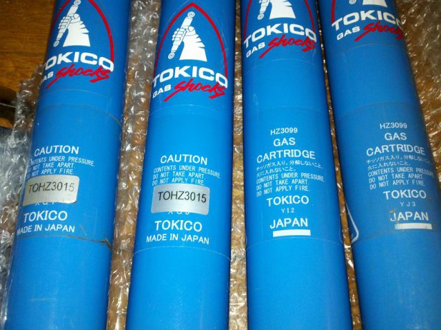
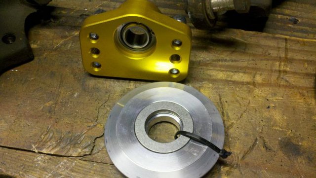
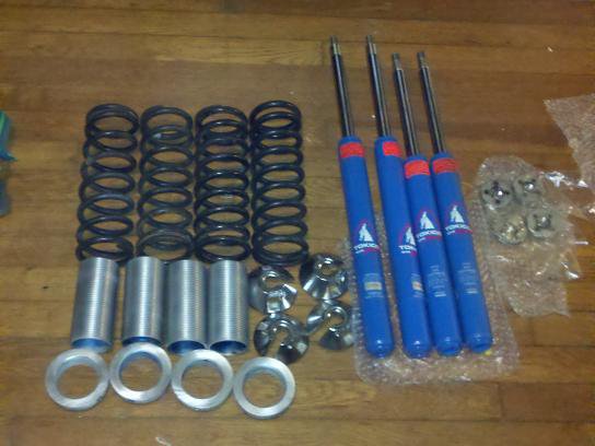
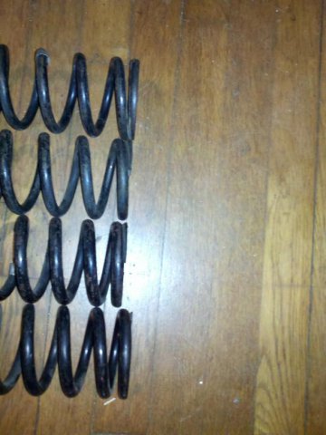
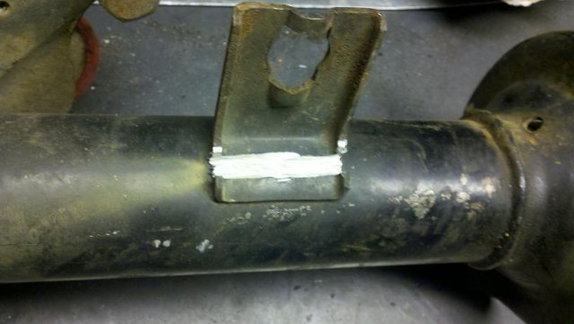
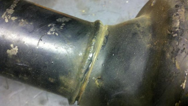
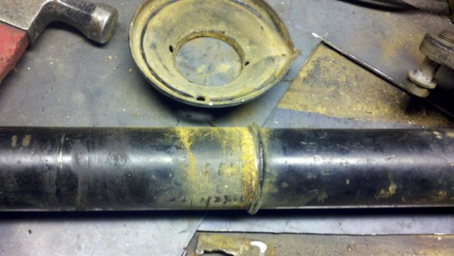
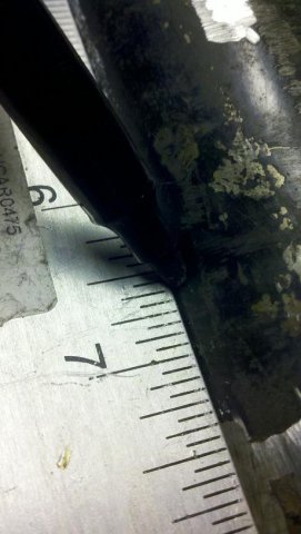
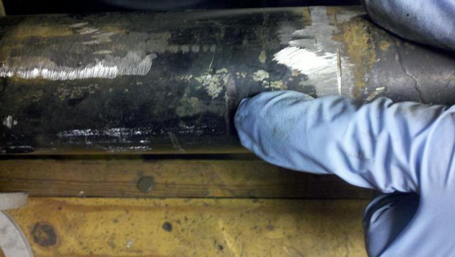
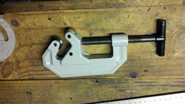
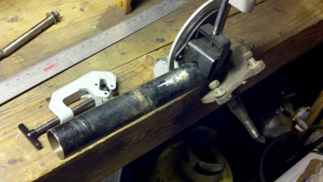
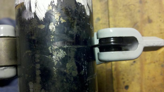
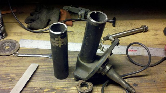
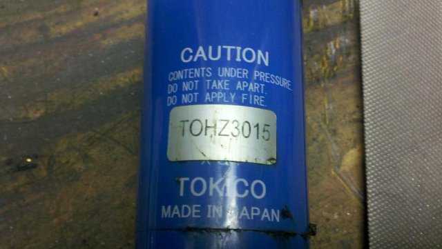
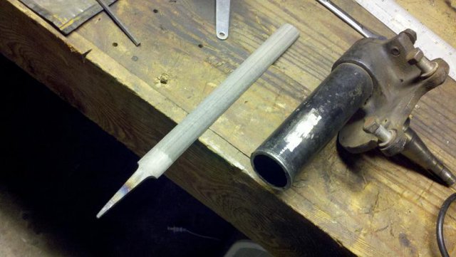
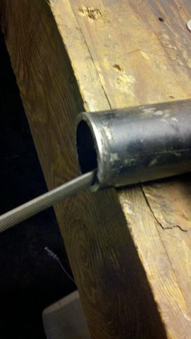
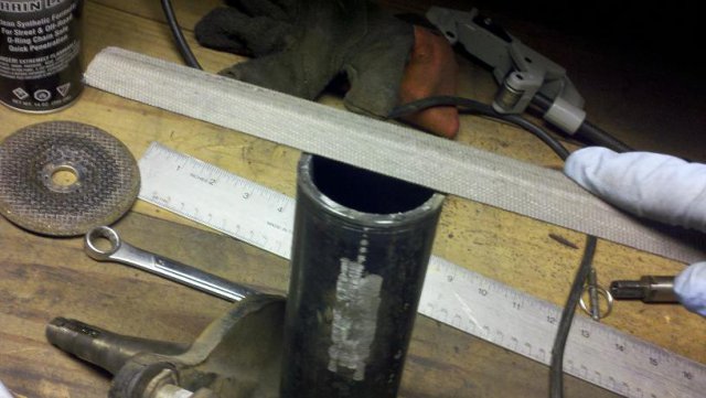
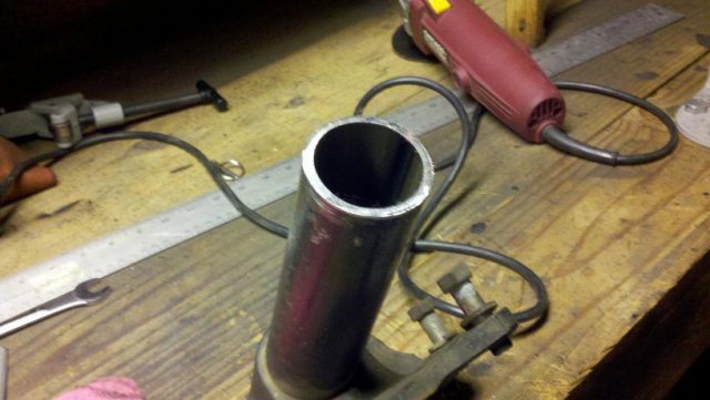
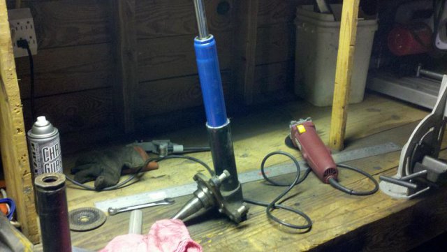
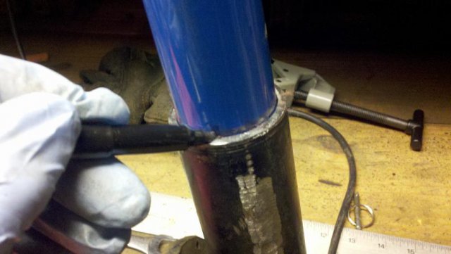
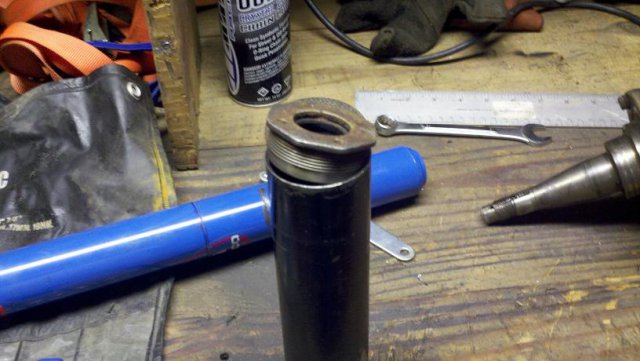
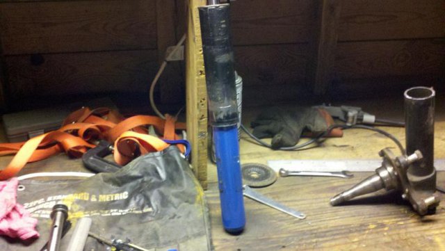
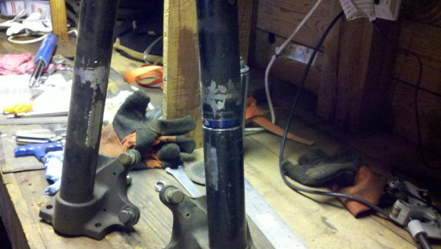
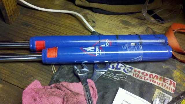
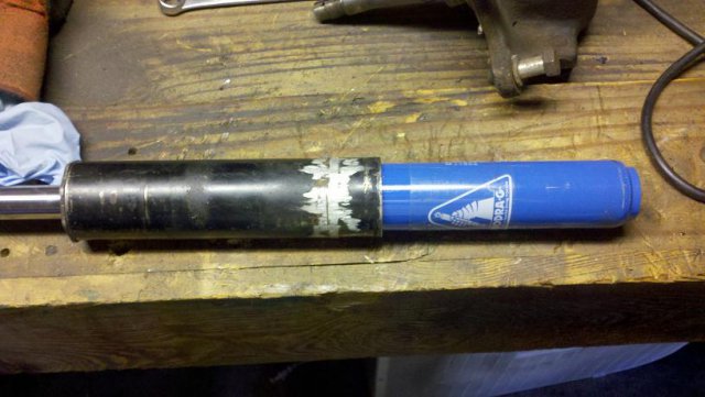
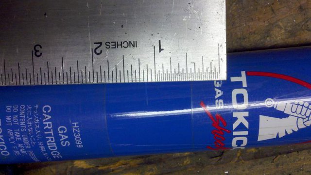
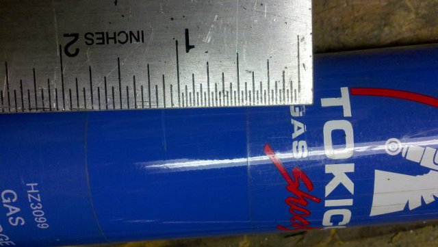
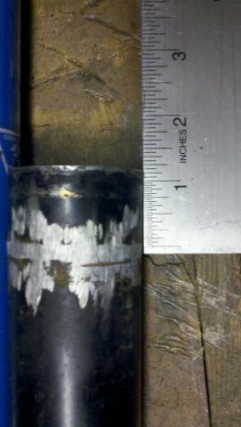
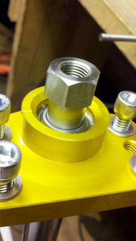
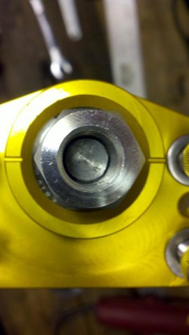
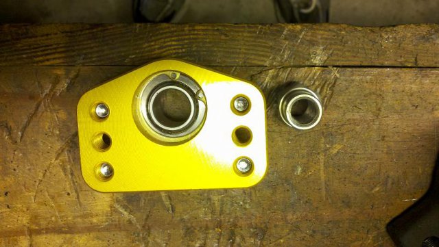
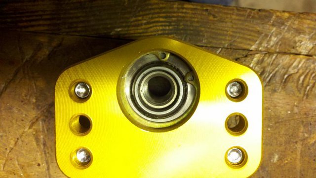
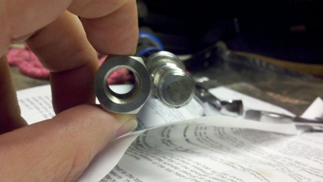
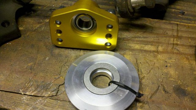
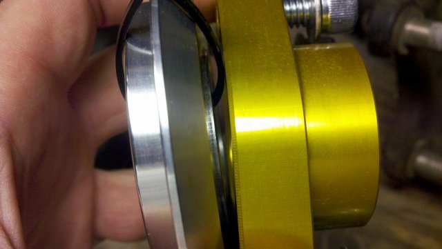
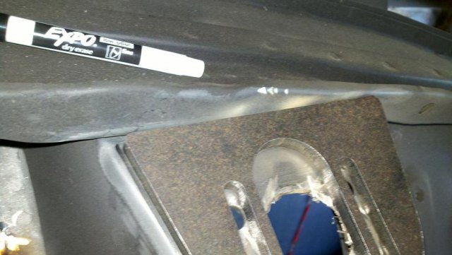
I started sectioning my struts and prepparing for my coil-over install and thought I'd post my experiences and pose some questions. I purchased a set of Tokico struts part numbers TOHZ3015 and TOHZ3099. 2.5" diameter springs by 10" length 225/lb and 250/lb. 5" threaded sleeves with adjustable collars. I then purchased the Techno Toy Tuning weld-in camber plates and top hats with bearings. So question one, my threaded sleeves have no anodizing on the threads and blue anodizing inside indicating they are pretty worn. The threaded collar is not very tight on the threads and the threaded sleeve is not very tight in the strut housing. I was told this could be because they are 280z threaded sleeves and I have an early 260z and the play in the sleeve is not really that big of a deal and is nothing I should worry about. The part I am worried about is the play in the threaded collar. Is everyone elses adjusting collars have a fair amount of play in them when screwed on the threaded sleeve? Should I look into buying a new set of the correct diameter threaded sleeves? Question two, One of my 10" long springs is about 3/8" longer than the rest of the set. Will this cause handling issues or can I simply lower the adjusting collar when installed on the car to get the proper right height as al the other springs? Should I consider buying new springs? Ok on with the install, I followed the instructions listed in Johnc's website at BetaMotorsports.com I am only sectioning the front strut tubes as I am doing a Q45 r-200 rear end install and using Techno Toy Tuning's custom strut tubes and they will fabricate a custom strut housing to fit my rear strut so I'm only going to be showing and asking questions about the front tubes. I cut off the brake brackets and lower spring perch. Don't try to grind the entire bracket down smooth with the strut housing as you will waste time and grinding wheels. All you need to do is cut into the spot welds on the brake braket and then remove the braket with a hammer. Using an angle grinder with a cutting wheel SLOWLY cut into the spring perch just above the weld being careful not cut into the strut housing. Again using the trusty hammer smack the perch all the way off the strut housing. Using about an 80grit flap disc smooth out the weld the perch was attached with. Again take your time, you do not want to thin the strut housing tube. Following the instructions on betamotorsports measure 6.5" up from the top of the spindle housing Opposite of the spindle and make a mark. Make a scribe into the metal and then place a tubing cutter on the scribe. I bought my tubing cutter from lowes for 20 bucks. You need one big enough to cut through 2" pipe. Do not try to do this with a chop saw or sawzall. These cuts need to be perfectly perpendicular and only a metal lathe or tubing cutter will do the job right. Placing the strut housing in a vice take the tubing cutter and make the first round. The first cut needs to be looked at VERY CLOSELY as the tubing cutter will sometimes want to "spiral" down the strut housing instead of creating a nice perpendicular cut. Slowly tighten the cutter after about every 3 or 4 revolutions. You should end up with two pieces when its all said and done. You need a bastard file to take out the burrs from the tubing cutter. I chose to buy one with a curved side and a flat side. Makes things a bit easier. We will do the beveling later on but for now just get the burrs out of the way and flaten out the rough spots on the top. You want to do this for each side of the strut housing. Now that the cut openings are clean we can slide in the actual strut. Now we need to figure out exactly how much of the strut housing we are going to remove and to find that out we slide in the strut to the lower half of the housing and make a mark on the strut tube but make sure the strut is ALL the way in the lower half Remove the strut from the lower half and slide it in the upper part of the housing. Make sure the gland nut is all the way tight on the upper strut housing. Make a mark or light scribe. Now here's where I had a mini heart attack...saying to myself, wait, somethings not right...Keep in mind I haven't sectioned anything yet, merely cut the strut tube in half. When I ordered the camber plate tops I told them I was getting them for the front but they only sent the bushing adapter for the rear struts so I assumed the thin threaded struts were the front. It was only later after I came back inside and hopped on here that I found out the 3015 struts are for the rear and the 3099 are the front struts. Ok back to work. Using the same steps above, and the correct strut make your scribes. The scribe on the lower half should be HIGHER then the scribe made by the top half of the strut. You want to measure the distance between those scribes in order to find out how much of the lower portion of the top half of the strut housing to remove. Mine measured right about 1-3/16" of an inch. Whatever your's measures DO NOT REMOVE THAT EXACT AMOUNT! Your leaving yourself with the very real possibility of cutting your strut housings TOO SHORT! I will probably remove 1-1/16" leaving me about an 1/8" worth of play. This play will allow me to buy a washer that is about 1/8" thick and stick it to the bottom of the strut before sliding it in the strut housing and will take up the slack in the play. Installing washers is a much easier task then pulling out the ole' strut housing stretchers and trying to lengthen your overly short strut tube. There are so many write-ups on how to install coil-overs and section struts but they all say the same thing, remove 1-2" of the top half of the strut tube depending on how much you want to lower the car. Well in my case and many others im sure, they have said well hell I want the thing to sit as low as it can and cut the 2" off of the strut tube. In my case if I would have arbitrarily decided on cutting 2" then I would have ended up with a strut housing that was about 3/4" too short and an elevated heart rate. So hopefully this method and pictorial will be a guide to some who are still warry about exactly how much strut housing to remove. Ok so now that all thats straightened out back to the questions... Camber plate tops- Do I need to call Gabe at TTT and ask for a bushing for the monoball assembly? The bushing and nut only fit the back struts and Im only installing the plates up front. The front struts have thicker threads and If I" just threaded the nut on that was supplied by Tokico there would be considerable slack in the strut rod and monoball bushing assembly. Top hats and torrington needle bearings- Do the needle bearings sit directly on the bottom side of the anodized monoball assembly or is there supposed to be another washer or bushing that the bearings seat to? You can see in the above pics the bearings would simply sit on the bottom side of the plate housing the monoball assembly. Is this correct or am I missing something? Thanks
-
Quick question regarding front subframe replacement
redneck1545 replied to AkumaNoZeta's topic in Fabrication / Welding
I would use 2x3 for the subframe connectors and 2x2 for the front frame rails. And thats why I love this place, so much information on here. I've been building my car in my head since back in 2004 and then I found this website and have been sifting through the massive amount of information ever since. -
Quick question regarding front subframe replacement
redneck1545 replied to AkumaNoZeta's topic in Fabrication / Welding
find a good metal dealer/steel yard. Most suppliers will carry or can at least order .085 walled 2x3 square tubing. I ordered a full 20' stick for my subframe connectors. Don't know what your plans are really but I tied mine from the rear control arm mounts all the way up to the T/C box. I can give you pics if needed. Lets tackle the first problem with the floors and 2x3 tubing though. 1" stays below the floor boards and 1" comes into the cabin area. I made custom floors in two sections per side because of this. The left outer and inner as well the right side outer and inner. I came across my measurements, as far as the bends in the outer pieces go, the other day and as soon as I find them i'll post em up for you. I made my floors from 16ga steel and connected them to the trans tunnel, aft and fore floors as well as the side of the subframe connecter with 1"x1" angle out of 16ga as well. It helps if you have access to sheet metal brakes and shears. Now the second problem of relocating your front frame rails 1" higher...Dont do it...It will cause an unforeseen amount of fitment issues with everything else that attaches to them. And I think your confusing subframe connectors with frame rails. They are not the same. If your just replacing your floors and subframe connectors your NOT replacing the whole sha-bang as you call it. Merely from the T/C mount back is getting worked. We drill the hole 1" higher for a reason. If you were to move the entire front frame 1" higher in an effort to not drill the hole your creating alot more work than needed. It's much easier to drill four holes for proper suspension geometry than it is to fabricate a whole new front end. Your steering rack and more importantly, your engine will all be one inch higher if you were move all that stuff upwards too. Your CG would be WAY higher, which completly negates any advantage you just tried to create by lowering your car in the first place. I think you need to do a little more reading, your thoughts about roll center/suspension geometry and such are skewed. Get through the floor and subframe replacement first and then decide what else you want to tackle. -
Floorpans/frame rails help... is this safe?
redneck1545 replied to mditt8671's topic in Fabrication / Welding
The picture above is called the T/C box and there are several people on here who have fixed the stock ones or fabbed up some custom ones and made some serious modifications as far as adding heim joints and such. I'd be willing to bet my left nut that there is ALOT more rust that you think. Just by looking at the floors and the T/C box as well as the front cross-memeber mount there is a fair amount of rust. Having just gone through an entire strip and blast on my 260z I can attest to the amount of rust popping up in places that looked solid as can be. Don't be afraid to look around with a hammer and a screw driver, but once you find the cancer places decide how far you want to restore this thing. I chose to take my junk-yard rust bucket all the way down and put it up on a rotisserie and blast the entire chassis and coat with epoxy primer and Zero-rust. The places I could "see" before I blasted were the LEAST of my worries after I got through blasting. Just my $.02 -
Floorpans/frame rails help... is this safe?
redneck1545 replied to mditt8671's topic in Fabrication / Welding
If your not VERY ocmfortable with sheet metal work yourself, the Zedd floors are worth every penny. I just made my own floors out of 16ga and it is not a job you should take lightly... You might want to look into replacing the subframe connectors while your at it. Chances are if you floors are that bad off then your sub frame connectors are not far behind. Might want to look into how much rust the rest of the car has if the floors are that bad. -
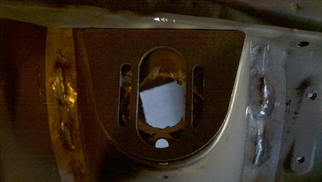
update as promised. I'll be getting the cage and camber plates welded by a proffesional this week. not that I couldn't do it personally I've just been having nightmares about the possibility of me hitting a hard bump and seeing my strut assembly come popping through the hood . So I figured I'd better leave the "its gotta be welded right the first time" stuff to the pro's. So far I just finished the seat mount dieting plan and prepping those parts for zero-rust treatment as well.
-
Sorry for the lack of update...I'm still sorting things out with it. And I bought a new toy, so money has been a little tighter. More to come soon!
-
Looking to buy a SBC 240z, what to look for?
redneck1545 replied to 44magnum's topic in Gen I & II Chevy V8 Tech Board
As others have stated, its not a good deal at 8500 man sorry. Keep looking. -
heres some of the previous stripping and body prep that i did a while back. http://forums.hybrid...__1#entry886114 beware, this was before i discovered picture resizing.
-
I used to be a HVAC service tech and repair man. I now fly planes for a living, much better career choice! You will definitely need a bigger breaker box BUT your house is wired for 220v...The AC "double pole" breaker is a 220v breaker and thats the same style you will need for your tig. A 220v line is nothing more than a paired set of two 110v lines. Also, there is above post that mentions 2 phase...there is no such thing, just single phase 110v/220v and then you have the 3-phase stuff for big commercial buildings or shops. You will have no problem running 220v to your tig as long as your service wire that feeds INTO to the breaker box can handle a larger amp load. Worst case scenario, you'd have to run a new larger diameter (smaller gauge) service wire to a new bigger breaker box with more posts and then run a 220v line to your tig. Either way you have to get a new breaker box as your is full, unless you dont want Air conditioning for a while. Hope that helps
-
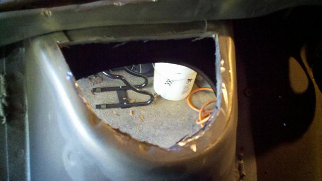
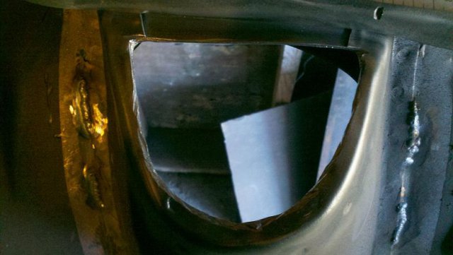
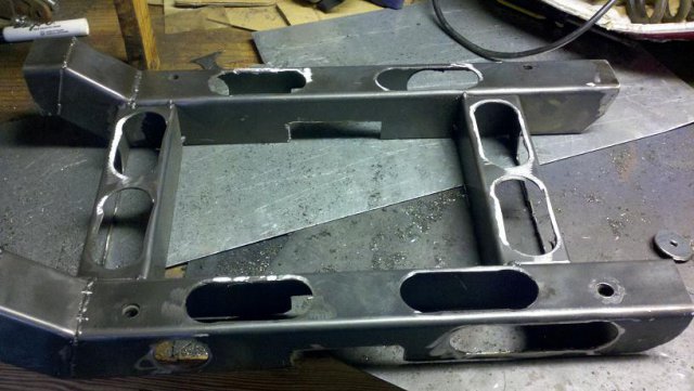
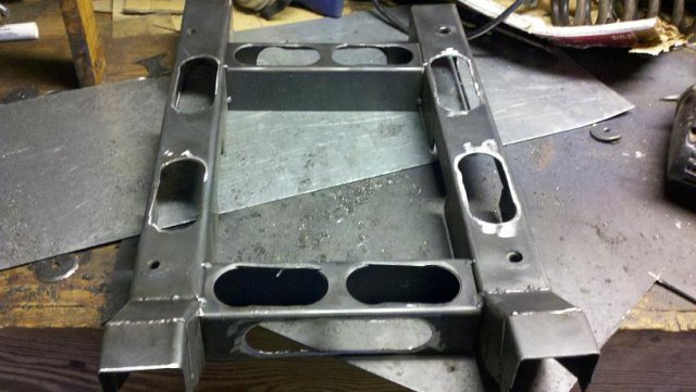
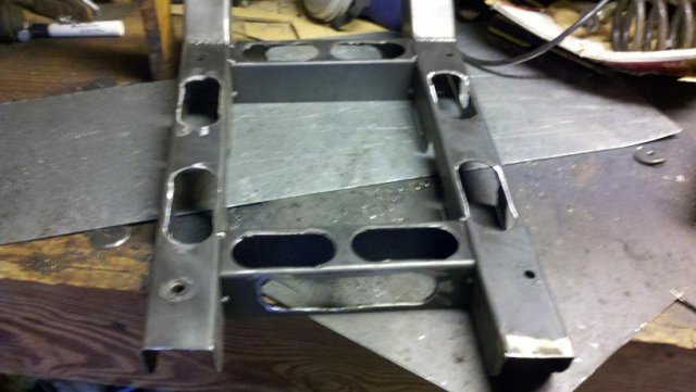
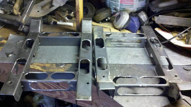
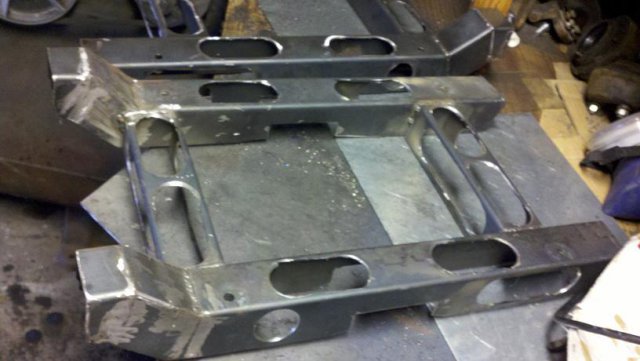
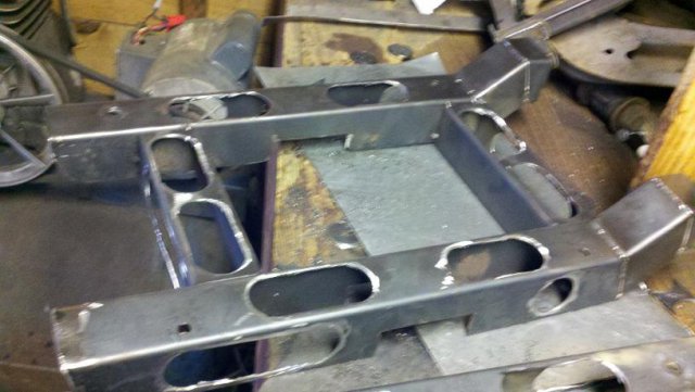
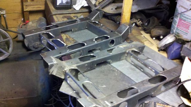
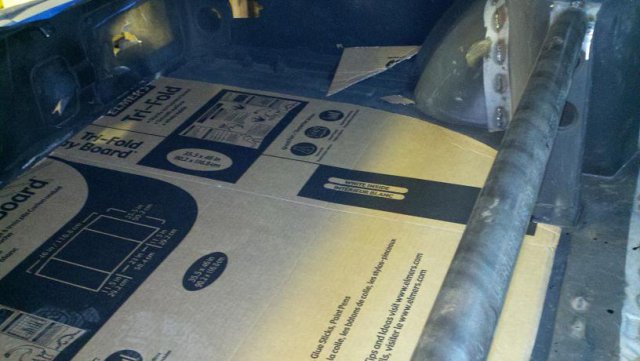
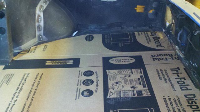
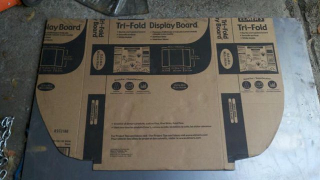
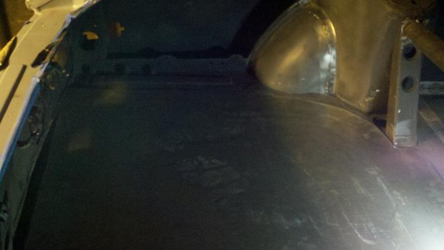
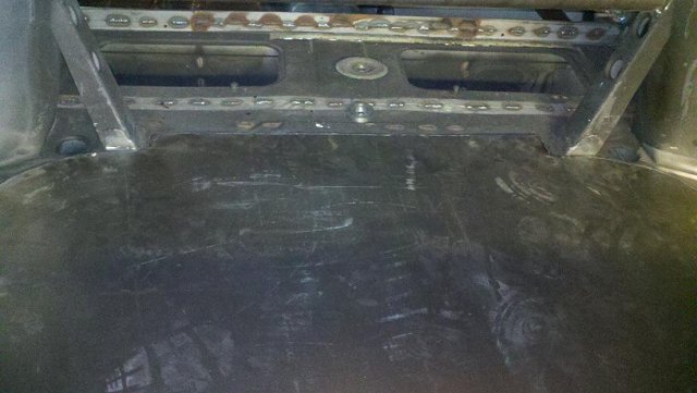
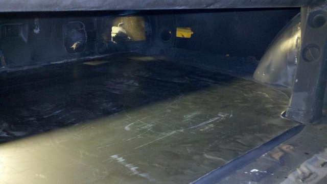
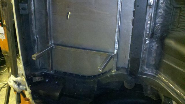
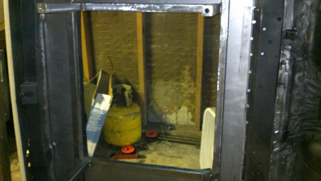
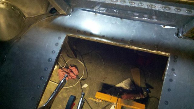
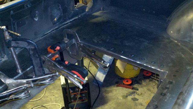
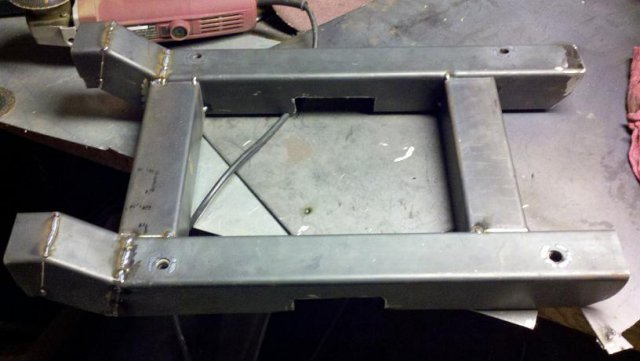
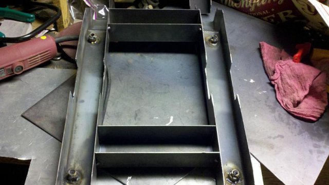
Update for those who are watching. No more cage stuff until I figure out wat direction I'm headed with it. The dash hoop location is kinda what it putting it on the back burner. The wrong location means i'll end up covering up too many bolt holes where things are supposed to go and since that hoop isnt really moveable I'm gonna wait until the car has some more stuff in it before I continue with the cage. So for now I've got a little four point cage that needs to be welded and painted. BUT, I haven't been entirely lazy lately and have been working on the sheet metal that will cover the old spare tire well where my fuel cell will be located as well as some seat mounts for my sparco torino 2's to bolt to. I did order some sliders (sparco part number 00493) and had to modify them to work with what i've got goin on. I pretty much just copied Myron's design on both the seat mounts and fuel cell cage design...if it aint broke dont fix it. Alot of people have made their own stuff up in this area but his designs are pretty much rock solid in my mind. I copied his plans using the 1x1 square tubing, and 1/8" angle iron for the location mounts. The only thing I changed on the fuel cell was I mounted my nuts inside the down tubes instead of having studs extend outward. This makes for an even cleaner install IMO. The seat mounts were made from 16ga steel sheet that was bent in a brake. (myron cut one side off of 2x2 square tubing). After final welding and prior to painting with zero-rust inside and out I plan on putting these things on a diet by cutting several 1-1/2" holes in various locations and cutting the metal between the holes to make a long oval shape. With the sliders and the 16ga steel these things are just too heavy IMO. Anyways, enough talking...enjoy
-
Bump...also looking for any of the rear end conversion parts.
-
nobody has any opinions or other ideas??? I guess it's back to building the seat moints an maybe throw some Zero-rust on the seams I stitch welded.
-
From what i've read on here on a few threads yes...This is normal and will not pose a problem. I think you have to get the 87 z31 seal though...sift through the stuff on here or contact 280zcar as he has this exact setup using pentagon style hubs.
-
If your talking about the seating of the front seal against the back of rotor there will be an 1/8" gap on either the round or penatgon ones from what im told. The round ones are supposedly the incorrect ones for the swap that im doing which is why I went with the pentagon style. The pentagon style does change the offset by a positive 3/4". I dont know if the round ones change it for the worse or not. Hope that helps
-
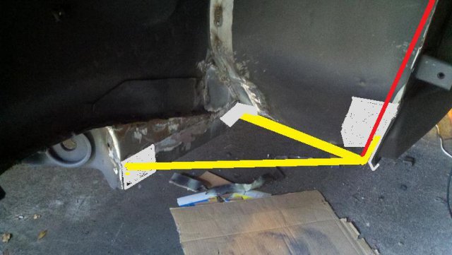
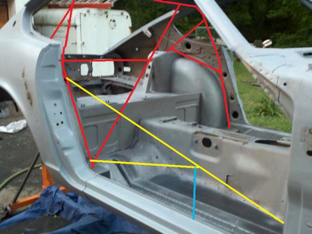
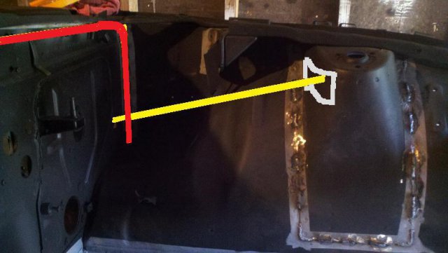
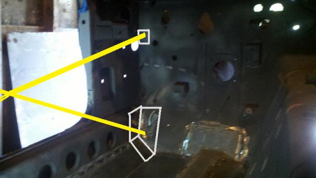
Ok so here goes. This is in the list of options that im considering. Not adding the low high bar to make it easier to get in and out. Adding the blue straight down bar to tie into the rocker if it is neccessary. With no low high door bar the red vertical bar will be non-existent. Penetrate the high/low door bar through the firerwall/footwell and plate, attach the portion that sticks through with one straight horizontal bar to the subframe connector (petes dimensions 1.5"x3"x0.095 wall I believe...maybe 0.083 wall) plate with .100" and then notch into the horizontal bar and attach one angled bar to the front of the sub-con right behind the T/C mount. adding a plate for attatchment points. If I do add the low/high door bar I have come up with this. In the pic above the red bar will be neccessary as well as the following pics... Both door bars will penetrate the firewall and attatch to a firewall hoop. Firewall hoop will have same subframe connector attatchments as well as a strut tower attatchment. My only questions are can I be safe for a streetable car with no firewall hoop and no Low/High door bar and just the high/low door bar attatched as described ore do I absolutely need the firewall bar and the low "x" door bars to have better peace of mind? This is pretty much a replica of Dans cage now without the tube front end, which brings to question are the down legs on the firewall hoop going to be wide enough or are his wider since he has no frame firewall forward? Awaiting advice...
-
I did clean up the notches today so they fit a god bit better. I also prepped the rest of my seam welds for paint. I guess getting busy on another part of the car is my way of dealing with the indecisiveness of me figuring out what route im going to take with these door bars!!! Im not really sold on the dash hoop as I still want the dash and most of the creature comforts such as heat so I dont want to have to cut in the dash too much to make the dash bar work with a stock dash. The other option I'm leaning toward is to penetrate the floor like Dan did with his cage and do a firewall hoop and tie the hoop into the sub frame connectors and the frame rails just behind the T/C mount where my subframe connectors are welded to that. I think with the right plate and positioning of the bars I can do a straight horizontal bar to the subframe connector and another angled bar to the subframe connector just behind the T/C mount. I've also been contemplating losing the low/high door bar all together to make this a little simpler as well as more streetable/daily driverable. I'll post some pics of what im thinking.
-
Cedar shingle is one of the most structually sound woods on the market.... No really IMHO, listen to what others have said and it will probably pay off in the end. If your still stuborn like I was then spend the 500 bucks to rent some equipment and sandblast the chassis and see what your REALLY hiding under all those areas you think are sound. at least in this case you will know what direciton to take with the tube chassis or another chassis
-
I actually have already sourced the spacers needed. An I already have the hubs as well but they are the pentagon style (the correct ones) The round hubs will not work for my conversion. Thanks though.
-
Glad to hear it proxlamus! More to come soon...gotta concentrate on school work for a bit then I'll be back at it. Thinking of adding some pics of using the notcher itself to hopefully eliminate confusion of cutting wrong angles or cutting the bars too short from making an improper notch. My goal is to get to cage done but it I have time i'll try to add some "first time notcher" tutorial pics sometime.
-
This is for a jeep frame but the process is the same. Hope this helps. http://jeepdraw.com/images/jeepdraw/TM10-1513/TM-10-1513-FRAME.pdf There is also a thread on here showing the dimensions of our chassis if you want the exact measurements.
-
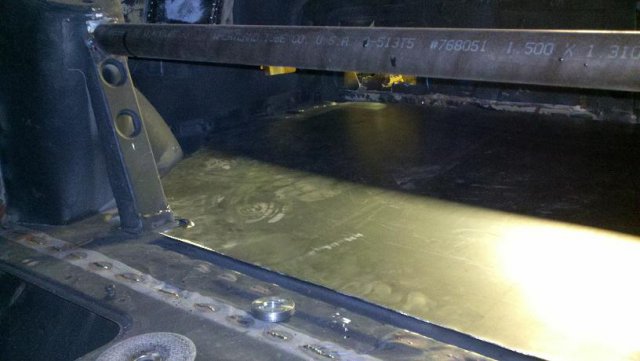
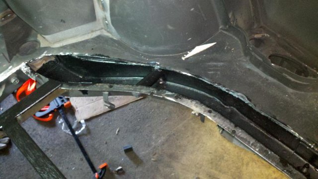
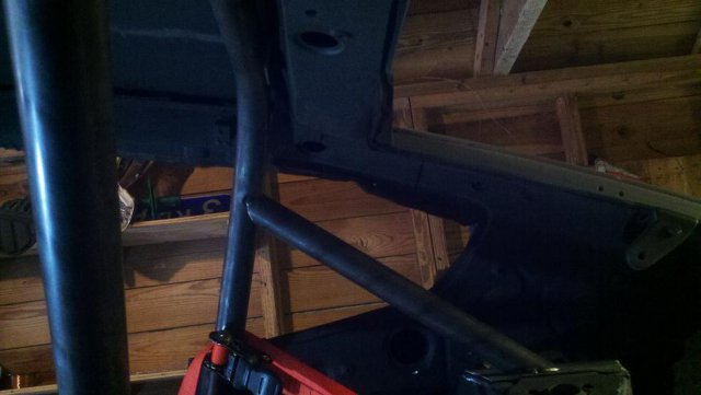
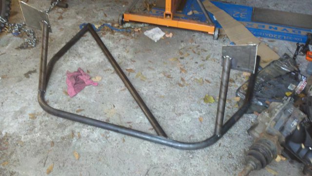
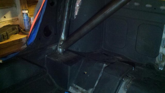
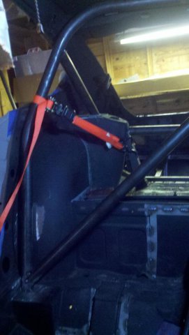
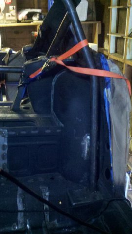
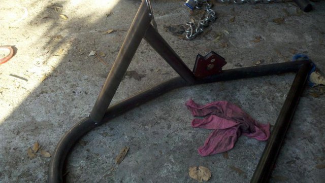
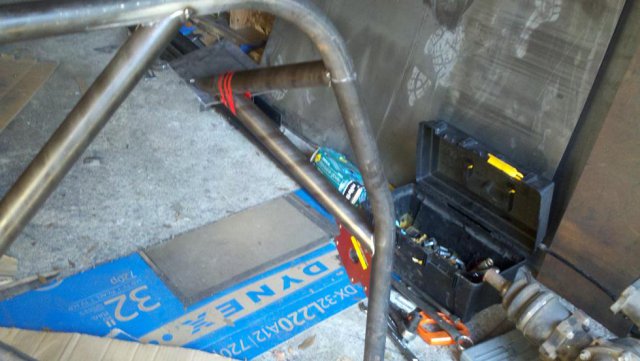
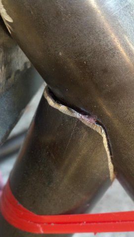
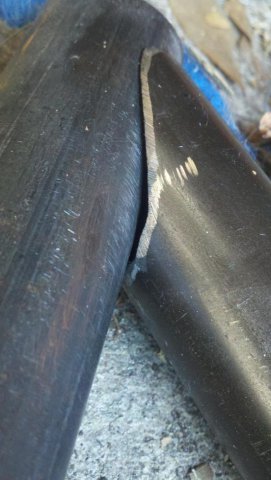
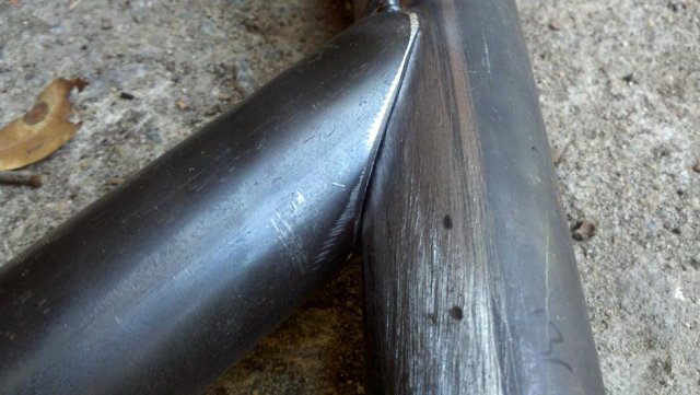
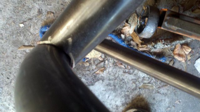
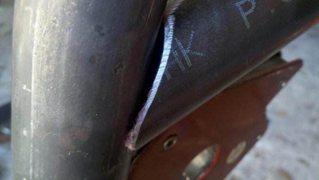
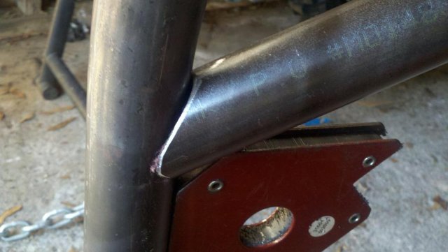
Ok so I got off my butt today and tried to finish the backhalf of the cage. Below are some pictures of what I came up with. Some of the notches didn't come out perfect so I'm going to include them to see if the experts approve or if I should re-work them and make a tighter fit. I dont know if I'm being too much of a perfectionist on these things. I did the welding on most everything else on the car but I will not be the one doing the welding of the joints because quite frankly this is my first time welding and I dont trust my welds for stuff that could save my life just yet, and I have some front camber plates that I need welded in so I'm leaving it to the professionals which just so happen to be a friend of the family who's been welding all his life and has been bugging me to let him help me with this car! I think my boxes on my main hoop are too freakin wide though, I put my seat in the other day to check to see how far I could move it back and the first thing it hit when moving it all the way aft was the box for the main hoop. Im gonna put the car together anyways and see if its something I can live with (I'm 6'1") before I cut into my boxes and make them skinnier. SCCA permits they cant be any shorter then 4" on any one side I believe and I haven't measured to see if that will allow the seat to move a few more inches aft or not. The strut tower plating is .100" thick plate. SCCA mandates a minimum of .080" and I'm hoping to keep this car sub 2400 lbs...we'll see how well that works out later on haha. Anyways here's the pictures of the stuff I did today. All these bars are made from 1.5" .095 wall DOM tubing. The first picture shows the main hoop location in relation to the roof line. I actually took some 1/8" angle and fit in between the headliner brace and the main hoop and used ratchet strap to make sure it stayed in place. It should leave me about 1/8" clearance between the dome light brace and the main hoop. Hopefully it wont rattle going down the freeway. I decided on making some adjustments to my cage after looking at some other cages vs Dan's cage. It just seems the better place to spread load and keep the chassis stiff is to plate the top of the strut tower and add attachments to the plate so thats what I did. The main hoop and diagonal bar from top to bottom will have a gusset welded in place later on. Could I do 16ga gussets? or should I stick with .100 plate? The main hoop will also have a shear gusset added to the wheelwell as well. And now the notches... Let me know what you think. Keep in mind these pics were taken really really close up so It might be hard to "scale" how big or small these gaps are.
