

MONZTER
-
Posts
832 -
Joined
-
Last visited
-
Days Won
34
Content Type
Profiles
Forums
Blogs
Events
Gallery
Downloads
Store
Everything posted by MONZTER
-
Good Question - To bend up the bracket accurately (I'm a freak about that sort of stuff) I would have had to either laser cut or CNC the blank out of 4130 plate. Well a lot charge at the Laser Company is $175.00. And I only planned on making 1. Now the time to set up the bending, and screw a few up getting the spring back just right as well as the compensation of bend = lots of time and money, again for 1 pc. Now after bending it would have to be fixture and drilled for the cross bolt that pass through the bushings = more time. CNC is easy to set up, and can run unattended unlike a bender or all the driving around to the different shops. So long story short more material cost, but less overall labor time. Again for 1 pc. Now production I agree 100% with you, hence why the part looks like it does, because it was designed for production bending. Oh ya, and my friend own the CNC shop :-P:-P
-
Yep, aka 240sx 5 speed conversion
-
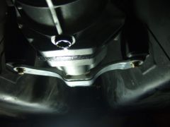
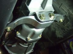
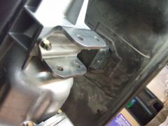
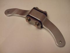
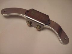
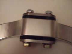
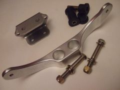
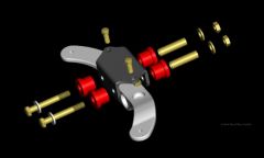
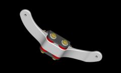
Hey All, I just finished up making my new transmission mount for the 71c swap. I'm pretty pleased with the results, so I thought I would share some pictures. It looks like It is going to be plenty strong, and the new design for the urethane bushing should keep the trans pretty tight. Another benefit is the improved exhaust clearance. I will be running 3.5 inch tubing from the turbo back, not the pipe tucks way up above the floor, which is pretty tough to do on a 240 with its narrow tunnel. So here are the specs: 71c trans Engine moved back 3/4 of an inch just so the valve cover fits past the hood catch -(the 71c mounts sit about 1 inch further back and the engine is now 3/4 back so a total of 1.75 setback on the mount) You can see the bowed shape of the cross member to allow mounting in the factory screw holes. 6061 T-6 CNC machined cross member 4140 Chrome-moly steel CNC machined trans mount bracket Urethane bushings from 73 up cross member 1/2-20 grade 8 hardware. I think I will anodize the cross member black and powder coat the trans bracket black as well (nothing too flashy on my car) Here are some pics of the CAD models as well as the finished parts. Click on the pics for a larger view from my picture gallery. Thanks Jeff I like the way it tucks up behind the tranny case
-
-
-
-
-
-
-
-
-
-
Already finished moving the diverter forward to the middle. Looks like it will stop the vortex from going counter-clockwise, and help it flow more linear. Good idea Jeff
-
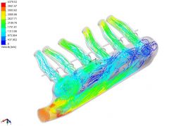
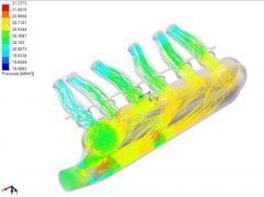
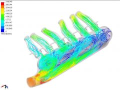
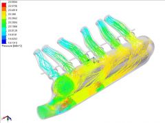
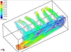
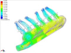
All right. the answers are in. Looks like an improvement in reducing 2 of the 3 vortices. The flow looks to be more even through the runners. The flow diverters seem to better even up the distribution of air. The bumps in the top seemed helped runners 2-6 with the vortices, but the first bump seem to be helping create the vortex in runner 1. So anybody want to post some sketches on there ideas to help get this thing perfect? Here are the results: Some new videos: http://album.hybridz.org/data/500/velocity_test9a_rev4.avi http://album.hybridz.org/data/500/velocity_test9b_rev4.avi http://album.hybridz.org/data/500/velocity_test9c_rev4.avi Thanks again for everybody's help. Jeff
-
-
-
-
-
-
-
-
-
-
All right!! a new update coming soon. Anybody want to guess if the new plenum design with the flow diverters and bumps is better or worse for the swirl and distribution of air?? I'm obviously hoping for better, but how much is my question? Thanks TBS Jeff
-
I think I have another oddball head. It is brand new and never been run. It was a nissam OEM replacement part, but for what I have no idea. It is a N-33. The combustion chambers are a wedge shape and it has a small exhaust valve with a large intake. The exhaust ports are square and there is no injector cuts in the intake. It is also only drilled for the 6 bolt intake. Any ideas?