MONZTER
-
Posts
821 -
Joined
-
Last visited
-
Days Won
22
Content Type
Profiles
Forums
Blogs
Events
Gallery
Downloads
Store
Everything posted by MONZTER
-
-
-
-
-
-
-
-
-
Ya and 90% of it will be chips for the scrap man.
-
I think making a plastic model and testing it would be a great idea, as I do believe in taking the CFD results for what they are, just first results. For me aluminum is easier, faster, and cheaper than rapid prototyping. The CNC proto is being cut right now, check it
-
-
-
 Hi Jon, You’re bringing back memories of my install. I use the camber plates that Eric and John make with the 5/8 ball. I think I remember the top threads on the stut being smaller than 5/8 by a little bit, and I also remember the large diameter of the strut, up next to the ball would limit the amount of articulation that the camber plate could achieve. What I did is turn out a "top hat" pc that installed into the ball from the bottom. This top hat reduced the id for the strut threads and then spaced the shaft away from the ball, allowing more articulation. Wow does any of this make sense? I could draw you some pictures if it will help. These struts are not plug and play, but I like em. Jeff
 -
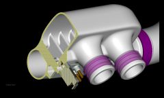
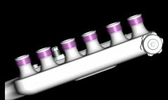
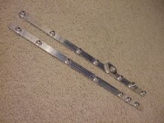
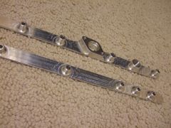
The runners are actually TWM ITB's that I merged together with a TWM intake manifolds. Basically, a bunch of cutting and welding to get the shape, angle, and new flanges. I will use staged injectors as well. And yes the Plenum will be CNC machined in two halves and then welded together. No casting right now. Check out my gallery for more pictures
-
I mountain bike on a 2.1 lb carbon fiber frame. Rocks hit it all the time, Not big rocks obviously. My carbon driveshaft from ACPT is about 10x thicker. Now, I would not put it on a rock crawler, but a road car, no problem
-
Does anybody know anything about this cars engine? I was told it was a straight 6 BMW. Oh the sound. Do you think a Z could ever rev and sound like this? Great video BTW. Watch it full screen with the volume UP http://video.search.yahoo.com/video/play?p=2005_gemenos_castellana&ei=UTF-8&fr=yfp-t-501&tnr=21&vid=1097229480
-
The carbon driveshaft has been great. I had an aluminum one before, and I kept breaking the staps on the clutch pressure plate during autocross runs (3X) I switched to the carbon driveshaft and it felt noticable smoother and less jarring when on and off the gas My car is all solid mounts for the diff, and suspension, and urethane for the trans, engine. I also changed clutch styles at the same time, so dont know if it fixed the problem, but have had no clutch issued since. The Yokes were the really nice heavy duty spicers and joints good for 500hp. Its not cheap, but I always believe it is all the little things that add up. As I first mod to your car? dont know if youll see the value, but when getting close to the ragged edge, I think its money well spent.
-
This is the one I have been using for almost 2 years now http://www.acpt.com/article2.html
-
-
I took an old one apart just to look inside, I could not get it back together, bearings went everywhere. OOPS
-
-
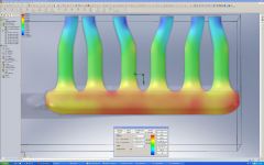
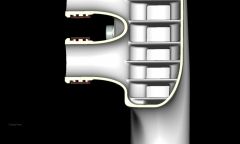
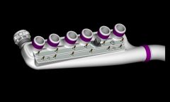
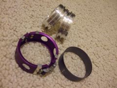
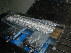
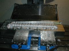
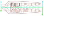
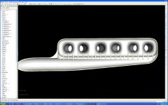
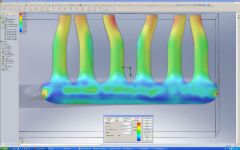
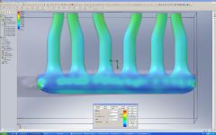
Well it’s been a long time since I have posted any new test results. I have been busy working on the plenum, really trying to get it dialed the best that I think it can be. If this work really pays off, well I guess we’ll see, But for right not the difference between this final design and my last design I almost settled on is dramatic. Before I had vortices that really hurt the flow balance between each runner as well as the total flow (see the first few pages). So here is what I did – Step one was getting the pressure across the slot evenly by changing the width of the slot, the thickness of the slot, and of course the taper of the sub-plenum. Even with this pressure balance out, I was still getting vortices once the flow moved into the plenum and stated down the runners. For example it had a runner mis-balance of about 30% - that’s pretty big if all this info really translates into real world. Step two was the idea of adding the ribs or flow diverters. By simply adding these and then adjusting their length slightly, I am now able to get the flow per runner balanced within 3% of each other. Keep in mind, there are 2 different ways I checked the runners. The first way was 1 runner at a time, but this is pretty easy with our plenums for z cars because we don’t have a bunch of odd runner shapes to deal with. When I tested this way all runners were the same within 1 cfm with a total flow of 226cfm per runner at 25”. My intake ports that were done by Rebello flow 210cfm at 25” so that should be a good match. I then went on to test the plenum flow with all 6 runners open at one time, and got the 3% difference. So what this means is if you hooked the plenum up to a flow bench with all 6 runners attached, all 6 runners would flow the same (within 3%) with a total of 671cfm. Now which test is more important, one at a time or all at one time, I don’t know, but I figure if they are both good then I have my butt covered. So here are some pictures of the test with just the slot and no flow diverters. Keep in mind the range is only about .25psi from the lowest to the highest on all of the pictures. Now here is the same plenum, with the flow diverters added. Big difference huh. Ron and I have been going back and forward on how to prove these test are valid and worth all the effort, I’m not sure, except for what the dyno will say. TurboBlueStreak who started this testing is doing some great work with port design and the computer. Interestingly enough his model of a stock port flow within a few CFM of what a stock port flows on a real life flow bench. I have also tested the flow of 40mm throttle bodies and have gotten the same flow numbers that were told to me by the guys making the extrudabody ITB’S. So I am confident the numbers are pretty close. I guess to sum it up – We just have to remember this testing is just a tool, and only part of the process. Call it very educated guessing and we’ll see how it ends up on the dyno. I am turning over the IGES files to the machine shop, and moving forward with the CNC proto. I’ll post some pictures of the real part once they’re ready. Thanks for all the input Jeff (MONZTER)
-
-
-