MONZTER
-
Posts
828 -
Joined
-
Last visited
-
Days Won
28
Content Type
Profiles
Forums
Blogs
Events
Gallery
Downloads
Store
Everything posted by MONZTER
-

Wheel Show! Post your pics of you wheels
MONZTER replied to k3werra's topic in Brakes, Wheels, Suspension and Chassis
You cant. Sal at Motorsport Auto ordered 2 custom sets from Japan. One for me and one for his 280. I am running 8" springs in the back with coilovers. The perches just fit above the tire so I actually can fit some 265 Kumos under there as well, its really tight. -
Wheel Show! Post your pics of you wheels
MONZTER replied to k3werra's topic in Brakes, Wheels, Suspension and Chassis
Panasport 16x8 19mm offset 245-45-16 Hoosiers -

-
Ron asked if I would run a test on his revised plenum. I thought it would be interesting to compare his revised design with his old design. I also thought it would be interesting to compare this single throttle open plenum design to what I am trying to do, as well as the HKS. Here is a link to Rons old results and pictures below of his new design http://forums.hybridz.org/showthread.php?t=117607 Picture of his old design Some pictures of his new design - 5 psi 20 psi As usual, click on the picture for a bigger view. Looking for comments, and yes Ron gave me permission to post his results, thanks Ron:D
-
-
-
-
-
I don’t know what you mean about the air coming directly into the intake? Part of the design of the air going into the bottom is that it works with the cone to distribute the air evenly. Typically as velocity goes up, pressure drops.
-
now thats looking better, and the pressure drop is much lower than the HKS. getting closer
-
-
-
So I took Monday and Tuesday off and took the family to Palm Springs. We stopped at the WWII airplane museum. Some really beautiful stuff in there. Anyway, I was checking out all of the intakes and air scoops on the planes. One thing they all had in common was the inlets for the radiators. All of them had a deep honeycomb "grill" that acted as flow straightners to the turbulent air. Hmm this gives me an idea. Jeff
-
Here are some shots of a standard 4x4x24 box with a 70mm inlet. Same 20psi boost at 793 cfm. Just as expected runner #1 not looking so good. Again, click on the picture for a bigger view:
-
I was looking at the analysis of the pressure on the HKS and realized the pressure range on the chart was pretty wide. So I revised the scale and now look at it.. 20psi was put in, but there is more than that in the inlet neck and a big pressure spike at the inlet bends. Looks to me like this intake cannot flow this much air at this much pressure without backing up. Tony D - I think I remember hearing you say the high HP cars would port or cut away some part of the plenum??
-
-
-
-
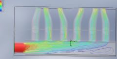
I ran the test at lower boost on the HKS Plenum. Looks the same, same equal flow distrabusion, so I wont be posting the pics. Can anybody see anything negative about the results above?, If there was room for improvement, what would it be, and how would that be acomplished. I would still like to see less swirling and less bends in the airflow.
-
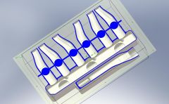
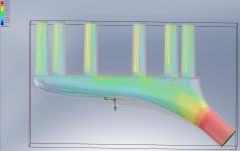
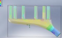
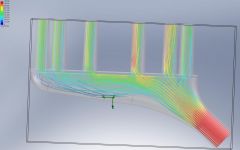
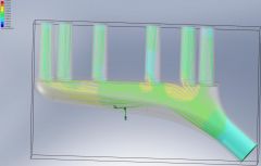
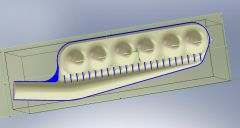
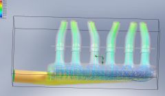
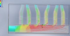
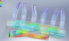
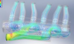
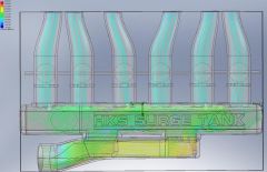
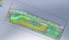
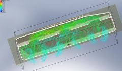
So once again, Thanks Tony D for the loan of his HKS Type 2 intake for testing. I was really interested in seeing how this plenum would flow given the success of it over the years. My plenum I have been working on has been plagued with a couple of vortices that have been causing the front two cylinders to run with less airflow. I wanted to see how consistent the HKS would be. So wouldn’t you know it? the HKS plenum looks pretty good. There is still swirling, but this doesn’t seem to be affecting the flow down the runners like my design is doing. The pressure looks to be even down the runners as well as the velocity. So check out the pictures below and let me know your comments, I know now I have more work to do on my design to even out the runner flow more. I have posted pictures of cut away views so everybody can see the internal baffling at work. I went as far as to model the plenum very accurately, down to the internal casting bumps for threads, to the shape of the runner inlet. It’s as close to the real thing as I could get. The test was run at 20psi boost 793CFM the inlet ID was 62mm so a inlet velocity of 4880in/sec was used. I will be running less boost on the next analysis and post the results soon. One more thanks to TurboBlueStreak for the lessons in the Floworks software by the use of his models from previous test. Click on the picture for a bigger view in my gallery Jeff
-
-
-
-
-