MONZTER
-
Posts
829 -
Joined
-
Last visited
-
Days Won
28
Content Type
Profiles
Forums
Blogs
Events
Gallery
Downloads
Store
Everything posted by MONZTER
-
-
-
-
-
-
-
-
-
-
-
-
-
-
I think it looks great. Remember safety, not to sound like an old fart (I'm not), but it is the most important consideration in my opinion. It doesn’t matter how cool or light it is if it isn’t safe. With that in mind keep a close eye on the joints to make sure you do not have any issues with the wraps. If the frame starts feeling "soft" hang it up. With the BB installed backwards you may have to use some locktite on the BB threads and pedal threads to keep them from loosening. Again great job, you should try some tig welded steel next time. It looks like your miters are done well. Best Regards Jeff
-
I actually work as a Design Engineer for a bike company called Felt Bicycles. We do a few Fixed gear bike. http://feltracing.com/08/product.asp?catid=1504,1525&pid=8717 All of them come with a "peanutbutter" wrench with a bottle opener built into it. It mounts to the seat tube braze-ons with wingnuts. Good beer and bikes go together quite well.
-
Hey, Whats up with the LHD? You going to run fixed or freewheel with a front brake.
-
Custom frame builders actually sell this type of bike. http://www.calfeedesign.com/bamboo.htm Check out the prices. Good Job, and cut that steer tube before you hurt yourself...
-
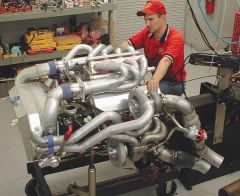
From my understanding a thick cast manifold will loose heat faster than a tubular manifold. A thick manifold has much more heat soak ability than thin material, especially if the thin material is stainless. Stainless is a horrible conductor of heat, and great at handling the temps. Think of it this way, have you ever tried welding a thin tube? Low amps is all you need for good penetration right? Now try welding a thick hunk of metal, notice how much more amps you need to get the material to melt? This is because the thick heavy pc has more capacity to pull heat. If you design a good header with room for expansion, personally I think it is all good. I built my own and it was by no means cheap easy or going to give me back in performance what I put into it, but I did it because I wanted to and I like building. If you are on a budget with limited finances then I feel the money could be spent better somewhere else. For me I had no budget and just wanted to make the coolest header I could. Here are some pics of it tacked up Jeff
-
http://www.lumenition.com/new/main.php/throtb/
-
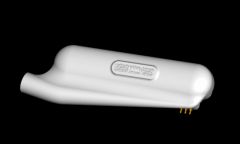
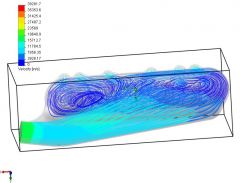
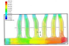
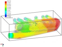
Tony I was just thinking about you comments on the old HKS manifolds. It sounds like the pressure drop in the large volume of the main plenum box isn't enough to balance out the floats. I wonder if you could tap into the system anywhere before the air goes into the large plenum and run this to the floats to get the boost like the sub plenum is providing. So a simple 4x4 box for the plenum with lines running to the float area to somewhere before the 4x4 box. Maybe before the intercooler?? Does this make any sense?? Just a guess
-
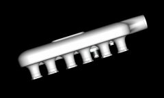
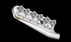
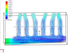
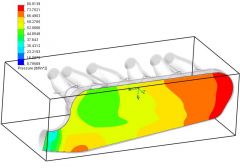
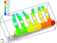
Not sure how the analysis was run, and if this was accounted for or not. This time I have to base the runner size on experience. Dave Rebello ported the head and was very specific about asking what engine size, cam, boost and HP goals. The end of the runners match to what he ported the head to. Actually not much bigger than stock. Interestingly the head flowed good numbers with the small ports @212cfm at 25" Dave said big ports doesn't necessarily mean good flow, but small ports help with velocity which will help with off boost performance. I guess well see Thanks for the comments, maybe TurboBlueStreak has some comments on how the test was run. Best Regards Jeff
-
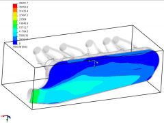
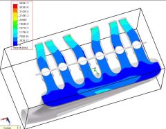
Hi Tony, Ya I would like to look at those plenums. I could reverse engineer it in Pro-Engineer so that it could be run on CFD software, but I can't speak for TurboBlueStreak if he will run the simulation or not:icon43:. Maybe after the new year we can get together and check it out. Thanks for the offer. Jeff
-
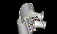
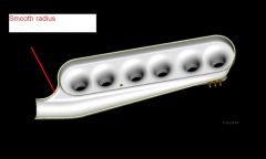
Hey Braap, Thanks for your comments, Unfortunately I don't know the answer, I'm just working from what just looks and feels like it would work properly. Helix posted a link above from somebody else doing the same type of design for a 4 cylinder. He had the slot facing the runners forcing the air down them. He determined this to cause turbulence in the runner and moved it to the middle like I have shown. I guess the best answer is lots of R&D to find out. Jeff
-

everyone that has built a custom intake for the L6
MONZTER replied to turbobluestreak's topic in Nissan L6 Forum
Like this, It scares me!!! -