MONZTER
-
Posts
828 -
Joined
-
Last visited
-
Days Won
28
Content Type
Profiles
Forums
Blogs
Events
Gallery
Downloads
Store
Everything posted by MONZTER
-
-
-
-
-
-
-
-
-
-
-
-
-
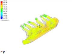
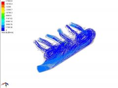
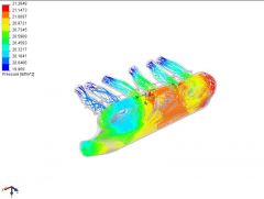
Tim, I PM'ed TurboBlueStreak who did the CFD work. Here is what he had to say: "Jeff as your question of how the cfd was run I ran the cfd with pressure openings. the runners were environmental and the inlet was 25psi. I'm going to review all my information and see if I can run the test in a better way. Hopefully we won't see extreme pressures or supersonic flow. " So it seems were were correct with our assumption. Here are the correct sizes of the model - Runners at the head = 36mm ID inlet into the plenum = 70mm ID I will post anything new he runs
-
Thanks Tony for the input, since I will have to make the weld fittings for the Wiggings clamps myself, I will just make them fit close together and no straps will be needed to keep them from moving. Tim this it mounted in back on top, hood clearance is going to be close. I have it mounted on the V-band clamp/fitting that comes with the BOV. I like you ideas about integrating the bottom half into the plenum, but it will not be possible to machine it the way I have designed it to be made. I think I will have to resort to welding it on after the plenum is finished and installed in the engine compartment. I think this will be the safest bet:)
-
-
Tim, that was great advice. After your comments about getting to the screws I went and looked at it. I would need like 10" long fingers to get to some of them. I thought at first no big deal because I will just bolt the plenum on before bolting on the manifold. Then I realized, how am I going to balance the TB's without removing the plenum. Its funny how you get deep into a project and so focused on the details that you miss the obvious. This is why I like this forum so much, great people with tons of real world experience. As for the added expense, It may actually be wash. I had to shorten the length of the air horns to make room for the clamps. The material stock size went down by a 1/4 of thickness, and that's a lot of weight and alot of savings when your talking a hunk of metal that big.
-
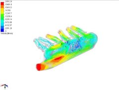
It looks to me like the runners are dumping all at one time to open air. You can imagine how much air would have to be pushed through to generate pressure like that with open runners. This is just me guessing again, as I have very little understanding of the CFD software. Maybe TurboBlueStreak can chime in on the details.
-
Tims Wiggins clamp Idea. I like it, I think I will go this way. Still have not figured out how to integrate the BOV besides welding it to the plenum
-

-
I plan on using the GPO control on the Tec 3. How are you running your vacuum lines? Are you tapped into the compressor or the plenum? How would the routing be different for a GPO control vs. an external? I have never looked into the external controller That’s a cool idea; I will look to see if I have room. The main problem is that the plenum will be made in two halves, surface machined in two operations normal to the seam line. This makes it difficult to get ports or details on the sides. I could always weld it in and blend it afterwards?? I am using Wiggens clamps everywhere else. I machine the flanges myself and only buy the clamshells (saves some money). That would make life easier. The thing I worry about is the expansion of the Wiggings clamps. They are designed to float and have about 1/4 inch gap between the flanges. I am not sure but I think when under boost the flanges might be pushed apart causing the plenum to have a lot of movement. Again maybe Tony D has some comments. Once again another good idea, do know how much money you are costing me today
-
Yep that is where I was thinking. Tim had some good ideas that might help.
-
Hi Tim, Thanks for the comments, good Idea of making a couple extra ports in the vacuum log. I currently have provided for in rail #1 the Air Idle Control, and the EGR. In rail #2 I have provided for the MAP, Boost gauge, Fuel pressure regulator, and the Compressor bypass BOV. Can you think of anything I am missing?, or some suggestion for future needs? I really wanted to integrate the BOV into the back corner of the plenum tank (I have a Tial) but there is no room. I have pushed the engine back an inch and the plenum is close to the brake booster. My plan was to run it in the intercooler outlet tube in front of the core support, Do you have any suggestions or comments if this will be a good place to put it? Is there an advantage to putting on the plenum? Thanks Jeff
-
Good idea being able to get back inside it for testing and tuning. I looked into it but the part wall thickness would have to go way up which would add a lot of weight. Also, the plenum is really big, and I just have clearance around it for the booster, my header, wastgate and such. Welding it is simple and easy, and personally I like nice TIG welds in moderation. I guess I could always cut it back open if I had to. I also think I would have to have a wideband sensor in each exhaust runner to find variations, I am not ready for that yet. Jeff
-
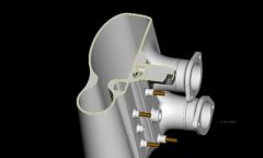
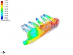
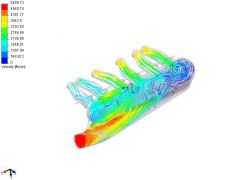
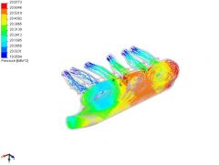
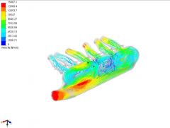
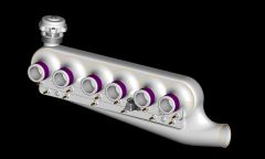
So, I have pretty much finished the design for the turbo plenum. You can see in the pictures below the complete assembly. I have integrated the AIC system as well as the vacuum reservoirs into the backside of the plenum. Should make for some clean hose routing to the throttle bodies and all necessary systems MAP, FPR, gauges, BOV, AIC, EGR. In this new version I have smoothed out the entrance into the main plenum from the entry slot where it looked to be a problem. Turbobluestreak ran some new CFD plots of this rev. Check it out and let me know your comments. I have the stock on order and this thing will be in the machining center next week. Click on the pics for a bigger view
-