

mobythevan
-
Posts
2250 -
Joined
-
Last visited
-
Days Won
1
Content Type
Profiles
Forums
Blogs
Events
Gallery
Downloads
Store
Posts posted by mobythevan
-
-
The dwell determines the amount of time the coil is charged between each spark, so it will certainly have an impact at high rpms. It is much better to run with dwell settings than to use the minimal HEI IMO. Sounds like the rich mixture is hard to light off. Looks like your on the right track.
-
Definitely post the datalog and msq on the http://www.msefi.com MSnS_Extrra forum and here. Those guys may be faster to scan logs and settings to point out possible problems.
The HEI module can charge the coil good well over 5000 rpm in 6 cylinder application. Mine worked to 6500rpm. My initial thought is that your AFRs are off at WOT at 5000. Even though the VE location may be the same for 3/4 throttle versus full throttle at 5000 and full boost in both cases, the amount of fuel delivered changes because the TPS reading will change. You don't have a wideband do you?
-
Use a 5v source for the pullup like with the GM module.
MSI comes in two flavors, v2.2 and v3.0
v3.0 has some added features that are nice like the coil drive tranistor on the board.
MSII I thought was a daughterboard that plugs into a v3 board and upgrades the processor, but MSnS_Extra code is not supported for that processor yet. So I would stick with MSI in either v2.2 or v3.0 and use the MSnS_Extra code.
MSII does support GM TPI nicely and supports the fast idle air controller in a TPI setup, so if you are going with a chevy V8 TPI install MSII would be good.
-
Someone with v3 proofread my responses, because I haven't built one, but think my answers apply
Comments in message:
Relay board:INJ 1 and 2 - to the 6 injectors, 3 each
FP - to the Fuel pump
S5 - to neg side of coil
Vref - to red wire on TPS (will make sure wiring is not reversed)
TPS - to white wire on TPS (will make sure wiring is not reversed)
TPS ret - to black wire on TPS
Tack VR+ - to Green/Black wire from the Dizzy
MAT - to the IAT
MAT ret - to the IAT
CLT - to the factory Coolant temp sensor
CLT ret - to engine ground ??????????
O2 - to my LC1 unit
+12v injector - 3 lines to the 6 injectors (2 each)
Run three injectors from inj1/inj2 and three injectors from inj3/inj4, that way you split the load across the two injector drivers.
CLT ret to engine ground is correct.
Use a 470ohm current limiting resistor to connect your LC1 to O2 input. LC1 wire to one side of resistor, other side of resistor to O2.
12V bat - to the battery through a fuse
Switched 12v - from under the dash
Engine GND - to chassic and engine ground
Make sure switched 12 volt is on during running and cranking
Dizzy wires
Black/white - to 12v can I run this off of the extra +12v injector terminal???
Green/Black - to Tach VR+ on the relay box
Green/yellow - not used
Black - to engine ground with the shielding wire
The 12 volt can come from the extra inector terminal, that is OK
Factory chassic wiring:
Blue - to the coil neg (to run the factory tach)
Black/white - 12v to the coil
So am I missing something or not??
Looks good, let us know.
-
I still think you want the 1K resistor to pullup on the FIDLE to the base of the transistor like it does to the "G" connection of the GM hei module(not inline lik you show it).
Yes, if pin 4 (180 degree) is the 4 slot output then everything else looks correct. I personally like to buy the megasquirt v2.2 from Jerry at DIYautotune unassembled for $134. That price rocks

Run either 024s13 code or the newly released stable code 029q
Better to stick with 024s13 because there are less options and less confusion.
-
I used a 240sx TPS. My 240sx TPS has 3 wires coming out of it to a seperate connector. These wires are connected to the relay board as follows:
Red to Vref
White to TPS
Black to TPS ret
-
On a v3 board pin 36 on the DB37 connector is for coil control. This how a coil connects to v3 board, nevermind the VR inputs:
Coil + always goes to constant 12 volt. Coil - goes to your tranistor which temporarily connects coil - to ground to fire the coil.
If you want to use the tranistor in the dizzy, then connect pin 2 to ground (transistor emitter), connect FIDLE to pin 1 with pullup resistor (transistor base), and the coil - is already connected to the transistor collector according to that schematic. Connect coil + (pin 7) to 12 volts on during cranking and running. Then stock resistor and ignition module in the schematic would be removed.
That should give you the correct way on all three setups, v2.2 with GM HEI, V3 with VB921, v2.2 with stock dizzy transistor.
Now get that thing ordered.
-
can you guys please not bid against me?
Ha Ha, lets see what Phil is willing to pay
-
If I read your schematic correctly you have version 3.0 board for Megasquirt?? If that is true then you don't use GM module or transistor in dizzy becuase it is already on your board? Just want to make sure. Otherwise if you have version 2.2 megasquirt board you are on the right track with the GM module.
-
Yes use the transistor in the dizzy if possible, cleaner setup. That is the transistor to fire the coil.
-
I would email Jerry jsut to be sure, it should have something like
MSnS_Extra024s13
But newer code has been released so you never know.
-
Also keep in mind that if you use an external transistor it will cause an inversion of the SPARK signal, so pay attention to whether or not you need to select "invert spark output" in MSnS.
-
I may be missing your question, are you asking about the transistor that fires the coil?
If you have a version2.2 board use the transistor on the car to fire the coil, or a GM HEI module (transistor). I just hooked up my Talon 4G63 and I used the stock Talon tranistor to fire the coil (actually two transistors and 2 coils, distributorless).
If you have a version 3 board you can fire the coil directly from megasquirt and not use the transistor on the car, because version 3 has the built in VB921 transistor.
-
What version of MSnS_Extra code are you running so you know if someone elses code will be able to load into your system?
-
I finished ordering my parts for EDIS8 on the 454 BBC. I got an EDIS8 module and two of the Ford 4 post coils. I already have the trigger wheel. Hopefully it will be plug and play with the info that you guys have tested and found.
-
I got the TC7117 from jameco, around $3. I also ordered the supporting parts from them. Download the data sheet and build according to the typical application on page 3, but make sure to substitute the correct values for 2 volt full scale operation. I turned on the decimal point to allow it to read AFR correctly and set AFRs from LC-1 to be 1v = 10AFR and 2v = 20AFR
It uses 7 segment LEDs and they wire directly to the A/D with no other components.
The circuit will then readout 10.00 for 1 volt and maxes out at 19.99 for 1.999 volts.
It has a potentiometer to calibrate, I calibrated by using my multi-meter to read the input voltage. It requires quite a bit of wiring on the breadboard and will be fairly busy on a perf board. I am going to look at proto-typing boards that may have most of the 7 segment buses already there.
Cost of all parts to build the circuit was less than $10 for me. The issue right now is that it requires -5volts so I need another regulator for the standalone gauge My breadboarding setup has -5v so it works in there. Just something fun to play around with.
Figure 5.1 in the datasheet shows how to build the -5volt regulator circuit
-
Read moblys sticky four or five times, and if you dont understand a part read it again.
I get questions all the time, by PM, phone, work email, instant messenger and 90% of the time the answer was in the sticky. I think its the "I don't need the manual" thing. But if you ask I will point out where it is in the sticky, becasue sometimes its hard to find one piece.
The sticky is very old and really needs to be updated with MSnS_Extra information and v3.0 board specifics. I haven't built a v3.0 board yet, I keep using v2.2.
-
What's wrong with using the old CAS and the original turbo dizzy?
It can be done, the instructions from Tony D. are copied into the sticky guide, but it is easier to use the 83 type dizzy, even if you have to swap to the 83 it is still easier. But either one can be made to work.
-
Source MSnS with the 4 slot trigger, the green black wire from the 280zxt dizzy is from the 6 slot wheel, not the umpteen slot wheel
. So you want to use the wire from the 4 slot wheel output on the KA24 dizzy. It was easy to tell if you got the wrong one because your cranking rpm in megatune will be crazy high if you have the 1 degree output. -
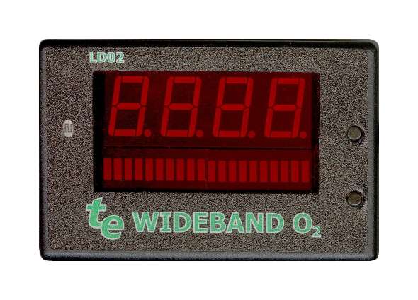
BTW, the circuit is built and works as advertised. As soon as my car is running again I will test it connected to the LC-1. Then I can build an enclosure like pictured above (LD02 style).
-
I want a display that looks nice in the dash like the LD02
I don't want a cheap multimeter setting on the dash, fine for testing purposes, but not my choice for long term in dash gauge. I am not knocking that solution, that is great to get started and set up the car, I am just looking for a "cheap" nice looking solution.
-
If the dizzy has an optical wheel in it like the 280zxt and one of the decoder rings has 4 holes then it will definitely work, don't worry if no one else admits to using it. Just pop it open and verify the decoder wheel. Or post pictures of the inside. That will give you the trigger for megasquirt and work OK with spark output since it was already made for ECU control (locked advance).
-
I forgot to mention, but you have to reprogram your innovate unit to match the setting you use in megatune either 1-2v or 0-5v
-
If you have configured your ini file to use 1-2v for 10-20AFR you may want to change to 0-5v for 10-20AFR. I have seen that recomended several times on msefi.com. Just gives better resolution for the analog to digital conversion.
I have seen complaints over there that the megatune AFR gauge reads different than the innovate gauge.


Welp.. all done.. sort of.. motor swap.. VIDEO and pics
in Non Tech Board
Posted
I knew you were crazy already. Good job on the swap.