Bob_H
-
Posts
783 -
Joined
-
Last visited
Content Type
Profiles
Forums
Blogs
Events
Gallery
Downloads
Store
Everything posted by Bob_H
-
Shoot, I got all wrapped up in showing the math, I completely forgot that we don't need a stioch value for meth while cruising/etc...... But it is important to know what it is so you can use it for the math. Your right - cruise, idle, etc.. use gas stoich - 14.7/1 I'm going to edit the first post to reflect that and make it more clear. In the end, you will greatly simplify your life if you can read and log Lambda - it takes all the guesswork out of what AFR to run and how much your injecting. To answer your question #2 if you run pure methanol - you would have to tune for a stoich ratio of 6.47:1, (or Lambda of 1.0 - hint, hint guys, get the picture? ). That takes into account its different burn effect. What you are doing by injecting meth or ethanol or whatever into your mixture is changing the octane of the gas - effectively giving it a higher octane rating, and a higher resistence to knock. In the end, if your motor can produce max power on pump gas,(i.e. its not knock limited), meth injection, higher octane fuel, etc.. won't make squat of difference. In our L6 motors, they are almost always knock limited - so higher octane gas, meth injection, water injection, etc.. all raise the knock tolerance and raise the ceiling on max power. What you are asking in that second question is way beyond the scope of what we can account for w/o some serious guessing.
-
Most WHP on a stock internal (except for a cam) L28ET
Bob_H replied to Boosted_JDM's topic in Nissan L6 Forum
Most definitely not steve. It was Cleve in Atlanta. I agree with burning up cheap cores then build it properly. He however, kept running junkyard bottom ends. He was building a big 3.0L stroker forged, etc.. but sold it to me first. -
Sorry for the delay about the methanol injection. This will validate what has already been said and provide you with the method to tune if you change the percentage of Meth injection. It is important to determine exactly what percentage meth you are injecting vs pump gas because it has a fairly significant difference in the target A/F ratio. The stoich A/F ratio for pure methanol is 6.5/1, Premium gas, (pump gas) is around 14.7/1 The difference between those two is 8.2 To figure out your target A/F ratio, multiply the percentage of either one and add or subtract it to the other. For example, if you are running 10% methanol - multiply the difference of 8.2 by .9 and add it to 6.5,(or multiply it by .1 and subtract it from 14.7) Net result: 10% Meth A/F target ratio for stoich,(NOT max power): 13.88 or rounded to 13.9 For best power on a turbo setup for regular fuel, (NO Meth), you are shooting for about 11.5 A/F,(12.7 for NA setups). To convert it over, it is easier and simpler to use what is called Lambda. Basically Lambda is a universal number for any fuel. Lambda of 1.0 is stoich for that fuel. So for premium gas,(pump gas), 14.7 = 1.0 lambda Best power for a supercharged/turbocharged setup is lambda of .78, (.88 for NA). If your setup won't show lambda, multiply your stoich point for the 10% meth by .78 to get your target A/F ratio. The nice thing about lambda is it doesn't care what fuel you put in or what ratio you are mixing - .78 will always be your best power tuning point and 1.0 will always be your idle/cruise/light part throttle point. Best power 10% meth = 10.8 A/F ratio I put the math so you can scale this equation for any fuel or varying percentages. I stated above that you need to be sure of what percentage meth you are injecting as a small change shifts your target a/f significantly. For example, 5% meth injection best power is about 11.1 and for 15% meth is 10.5. Another example, pure ethanol has a stoich of 9.0 A/F, E85 is 85% ethanol, so the stoich point or Lambda 1.0 is 85% of the difference between 9.0 and 14.7 or 9.9 A/F for stoich, and 7.7 for best power on a turbo application. Pretty low eh? Anyways, just wanted to provide the method to change what your tuning for. If you can switch your wideband to display lambda, you eliminate all the guess work and just tune for 1.0 and .78,(well the higher throttle settings will be in the .9 to .95 range). -Bob
-
RB26 with RB20 sump - no bottom mounting provision for gearbox
Bob_H replied to Mike Rowe's topic in Nissan RB Forum
Stony ran low 11's with no issues using only the top 4 bolts. You won't have any issues. -
Most WHP on a stock internal (except for a cam) L28ET
Bob_H replied to Boosted_JDM's topic in Nissan L6 Forum
520rwhp on a stock bottom end, stock p-90 head,(no porting) with unk aftermarket mild cam, turbo tom setup, huge turbo, at ~ 28psi and nitrous,(something around a 75-100 shot). The previous owner ran stock blocks all the time. (I say blocks plural because he would burn one tuning, pick up another at a junk yard and run it on the track for several months. -
You are spot on - and as soon as I get back to TX on tuesday I'll pull out my documents and put the exact numbers up and how you can modify your fuel maps when you are running Meth.
-
Something to consider on door design - the doors don't need to open all the way - I'd say up to about 30-40 degrees max. If you look at many aftermarket designs - they have travel limiters for the doors anyways which limit it to about 20-30 degrees total opening. I don't know if you incorperated that into your design or not.
-
Just make sure that the 1/2" clearance is from the actual pipe pickup point and not from the screen - as that has no effect on the pickup suction. Your design is exactly what I was going to do on my oil pan before I changed designs - however I was going to make the "diamond" smaller to keep the volume reasonable as with a big area, under braking it can still uncover the pickup. Intersting to see synthtk's pan has the loss of pressure under breaking issue. A big part of any design is the top plate - that can help direct oil into the pickup area vice dumping it into the areas outside of the pickup areas. There are good discussions on the V8 rX-7 forum where a new baffle plate was designed. -Bob
-
I don't think its the end all solution. It is a good solution - hence why I chose it, but there are better options out there - dry sumping being one of the best, and most expensive. The windage trays aren't going to stop dropping oil pressure - they are only going to help from getting air in the oil - i.e. it gives the oil time to settle down before it gets in the sump, allowing the air to seperate from the oil - they are only one part of the solution. In the end, what you are talking about will help, but not eleminate the problem - nothing really will. But if your not tracking your car really hard - you likely won't have any issue at all. -Bob
-
Good to see someone else using the stock flange. My only concern with your design is under braking - that is a very long sump front-rear and under braking you can see lots of fluid movement away from your pickup under even moderate braking. I'd seriously look at that trap door and do what you can to ensure minimal to no oil will flow forward under braking. Maybe a rubber edge etc... You just don't see long fore-aft design pans for that reason. Just something to consider. BTW, nice drain baffle design. -Bob
-
Hmm, here is their link: http://pdkfabrication.com/Dash.htm Worth considering. Thanks.
-
I found something today concerning the distance to put the oil-pan pickup. I wanted to post it here to keep this for posterity. BTW, no progress on the car besides stripping the paint from the suspension. I bought a 94 RX-7 with an LS1 to replace my BMW as my daily driver. Trying to sell the BMW, my 93 RX-7, etc... Oh yea, 12+ hour work days.. I do love my job though. Post: I would be concerned about locating the oil pickup that close to the bottom of the pan. On p. 147 of his book, Lingenfleter recommends following the oil pump manufacturers guidelines of 3/8” to ½”. To quote, “A pickup placed too close to the bottom of the pan restricts the pickup and could cause oil pressure problems at high rpm”. I spoke with the owner of Canton after buying their LT1 pan in 2001, because they offered multiple depth pickups. I especially wanted his opinion because he was familiar with the needs of road racers and I figured that Lingenfelter's engines were MAINLY used for straight line performance (Lingenfelter uses a dry sump set up for their ASA LS1 engines). The owner said that I could use slightly less than 3/8”, but that he considered 3/8” close to the minimum, even for road racing, for the same reason that Lingenfelter did - too much oil restriction at high rpm.
-
If you grind out the opening to fit the pipe - its almost identical. We compared them side by side. Its just poor machining/assembly tolerance. -Bob
-
What's your timeline? I may be selling mine if I decide to re-do the mounts for the stock RB ones?
-
If you get the SS autochrome ones - yes, re-inforce the weld. In addition, before you take it to the welder, take a grinder to the inside to clean up the welds and open up where the wastegate pipe comes back into the main pipe - the fitting is terrible and is fairly easy to clean up. The reason to do it before you take it to be welded up is incase you screw up and go too far - they can fix it. I have the HKS pipes and a good friend with a R32 GT-R picked up the SS parts and we compared them. With a bit of work, they are fairly close to the HKS parts - but the weld quality is absolute crap. The "pretty" weld is purely for cosmetics and you can see through it in areas. I think for the money, with some elbow grease, they are good parts. -Bob
-
I had a question recently about this thread - some more input since i posted this - the main reason many people have issues with the MAF after the turbo has to do with turbulent flow, reversion - i.e. reverse flow, etc.. It leads to times when the MAF see's less than is actually going by, and it can lean out the motor. The opposite is true as well - it sees too much, and tells the car to go rich. People have killed motors with the lean issue - when you put the MAF on the suction side of the turbo, it sees a constant pull - vs. a changing pull on the pressure side. Think of BOV's - when you close the throttle - it sends a pressure wave back to the turbo - which the BOV is supposed to help reduce/eliminate. If the MAF is in that tubing - it can actually see a reversion/reduction in flow and lean out the motor. Over time, this beats up the pistions/etc.. and can kill the motor. Food for thought. -Bob
-
craved - I knew I could bolt it, I just don't want to as they have a tendency to back out over time - the BMW oil pump bolts are prime examples. Rare, yes, but not something I want to deal with - so welding is the only option for me. strokerzedd - I don't see a benefit of the rear drain. It won't hurt - but why spend money on tubes and connectors when they don't dramatically improve things. Below is a copied from the discussion about the oil drain issue. Matt owns/runs a shop in Japan building high HP motors - very high HP motors. This is long, but a good read: If you're looking for soultions here, delete it because there are no solutions for a fictional problem. It's going to be dripping with sarcasm, too! What fun. Hang on to your shorts. That's right. You didn't read it wrong. The Internet spread BS on this subject has finally reached "urban legend" status and I feel it's time to set the record straight, vent, shed some light, whatever. What pushed me over the edge is a new post on Hybrid Z where the guy (Boosted Z I think?) gets some good #'s on the dyno but sees oil pressure falling off around 8,000 rpm. The first questions asked are "Do you have the oil restrictor?" etc... sigh... Are you serious??? Now we've reached the point where the drain back issue is so bad that the engine can't even do ONE DYNO PULL without all five quarts of oil ending up "trapped" in the head?? Give me a break, man. What's funny is that the RB26 is, what, 18 years old, but it never had oil drain back issues until Tomei started selling the stupid restrictor with a little hand drawn picture of high oil level without the restrictor and low oil level with it. Actually, it's not a bad idea, but I'm calling it stupid because of what it started. A little perspective: Obviously Nissan doesn't think it's a problem because they never addressed it in the 33 or 34 engines. Oil returns and pressure orifice are the same as far as I can tell. At least not any major changes for what seems to be a catastrauphic problem (sarcasm). Would someone PLEASE explain to me why Nissan can take a bone stock R32, R33, or R34 to the Nurburgring and go at full throttle, lap after lap, eight plus minutes per lap and never have oil drain back problems that rob the sump of oil, but a guy on an Internet forum can't do one lap of a two minute circuit or even one dyno pull, have oil pressure sag, and have everyone under the sun call out for restrictors and additional drain backs? No, not really; that was rhetorical. I've seen N1 and Super Taikyu race engines up close and even inside. Never seen any additional drain backs. Not sure of the Super GT engines, but they probably use a dry sump with scavenge in the head and no drain backs, to keep oil off the crank. Saw the HKS Drag GT-R up close too, and never noticed anything like that. There are probably thousands of track GT-R's driven in Japan alone that don't have this problem. My experience: Power numbers's? Don't know. Our dyno's here won't hold much over 700 without slipping tires (at least that's as high as I can get it), and I'm not a big fan of numbers on a piece of paper, so I really don't care. However, I can tell you that the most powerful RB26 I've ever built burried a 320km/hr (198.838 mph and don't tell my mom) speedo on the expressway at over 10,000 rpm. Modified HKS pump, no aftermarket restrictor, no additional drain backs, oil pressure holding at a rock-solid 115 psi. In fact, I've never used an aftermarket restrictor or additional drain back in any engine I've ever built... I've never had an oil pressure problem in any RB engine. Ever. I build 'em loose, too. Maybe some people are having problems. With the above, I doubt very much it's a "pooling in the head" problem. Here's why: Suck air in the oil pump and oil pressure goes to zero almost instantly. No "falling off in the top end". Some people shift gears and the oil pressure is magically restored (even though all the oil is in the head), only to have it fall off again as soon as the rpm's climb back up. Oil pressure falling off in the upper rev range can be caused by several things, the most common of which is cavitation. I would put money on it that most people running RB Z's are using the steel pans from the Z31? This not only eliminates the excelent RB26 sump baffeling, it also precludes you from using the RB26 windage trays. Foamy oil cavitates. What happens is tiny bubbles in the oil enter the pump under huge vacuum. A bubble that already exists is much easier to expand into full blown cavitation than oil with no bubbles. The bubble(s) expand to many times their own size, taking up space originaly reserved for oil. Once it hits the pressure side, the bubble collapses, but the damage is done. Less oil went through the pump. The faster the pump spins, the more vacuum is created, and the worse the problem becomes. Oil pressure that falls off as the revs climb is almost always caused by cavitation. This can also be caused by a too-small or too-restrictive oil pick up. Moving it all the way to the back of the engine couldn't possible affect this, could it? I watched a video of a guy going around the track in an RB Z. On braking and turning in only one direction the oil pressure would zero out almost instantly. Once the car straightened out or throttle was restored, pressure jumps back to normal instantly. Once again the common consensus was the 'ol PIHS (pooling in head syndrome). On decel or only turning in one direction? PIHS or bad baffeling in the pan/pick up location? You be the judge, but use common sense. The restrictor is good: But for the wrong reasons. The right reason is the same as a small Chevy or any other engine for that matter... The head doesn't have heavy rotational forces for two reasons: There's no heavy stuff swinging around, and it's only moving at half the crank speed. It doesn't need a lot of pressure, especially because the cam to lifter interface is fed by oil dribbling out of the cam journals. Pressure in the head is wasted, which is the reason for the factory restricotr. A smaller restrictor will keep the pressure to the bottom end higher in the rev range due to decreased VOLUME wasted in the head. The additional return is bad: There are two large returns in the rear of the head and several throughout the length of the left side of the motor. Due to crank windage, the ports on the left side of the engine are subjected to a vacuum because the crank is pulling down on that side of the engine. The one in the rear, right supplies windage to the head for crank case ventilation. Air doesn't pull down the left side if it can't come up the right. Under hard acceleration, oil wants to move to the rear of the engine. Some people install a large line from the rear of the head back to the right side of the front sump in the GT-R pan. Anyone see a problem with this? There's actually two. Under 1g of acceleration, not only will oil not move forward through this line back to the front of the engine, it gives the oil in the sump another path to exit the sump. Reason #2 is that the right side of the engine is pressure side and not the suction side. Crank windage at higher RPM can push oil back into the tube if it's not very carefully baffeled. It could work well in a rear sump if the hose is almost straight down and entering the left side of the engine. But this as assuming there really is a drain back problem. What I have seen/done: An additional line from the back of the head, under the plenum, back to the RADIATOR. Additional coolant movement out of the head. Very common mod on drag engines. Maybe someone saw this somewhere and mistakenly thought it was for oil and ran with it? Who knows. With the additional oil restrictor in place, the oil level in the hed would certainly be lower than without it, but I assure you that even with the stock restrictor, it's not even close to a problem. Especially not the problem it's been made out to be. Anyway. I feel better and will now step off of my soap box. I'm sure there will be arguments from people who had PIHS cured by these mods, or whatever, but you really need to stop and think about it. Especially given the factory stock cars not having problems on the ring, etc. Matt
-
Anything I use should be aluminum as steel to aluminum doesn't weld very well.... For the sealing question, absolutely you would take it all the way forward and backwards. No need to put holes if you go with trap doors as the oil will naturally push the doors open under no lateral/fore-aft load. -Bob
-
My sump is far from the stock sump - its 100% custom at this point. If your not familiar with putting the RB's into the Z's, you must convert it to a rear sump - it won't clear the crossmember. So my choice is limited to a completely custom pan or utilizing the RB20 rear sump pan - which has some severe limitations for my intended use. I have checked out the RB26 updated baffles/sumps and they won't really work as they are built if utilized in my setup, but I have considered their ideas. There have been some excellent discussions here and on the RB mailing list,(for those putting RB's into Z cars) about the oil in the head and its not quite as it seems. An engine builder who has built many very high hp RB26's,(up and over 1000hp), had some excellent input. Bottom line, his analysis showed me that what we have often attributed to the "pooling in the head syndrome", just doesn't fit that issue. I can elaborate, but the data makes good sense and I will NOT be including a head drain in my setup, (but I did expand out the returns).
-
Cheap RB for sale found on freshalloy: http://forums2.freshalloy.com/showthread.php?t=178007
-
In spite of some ideas from my wife at times, I'm not made of money. 2nd, it doesn't exist in a production form - i.e. its completely custom and 1 off. Mark is supposedly getting one made, however it is still nowhere near completion and the fabricator hasn't returned my e-mails.
-
I had the pleasure of playing with the Nissan Comp pan when it was out of a car. My original mockup had a diamond box - and i was looking for hinges. Most aftermarket pans I've run into have a diamond box vs. a square box,(i.e. parallel to the sides of the pan). Assuming a diamond, it comes down to a rubber gasket over a hole, (proven to work), a trap door, (on many "race" pans - again, proven), or a design similar to what GM has settled on with the LS2 corvette motors. A design which was influenced by the LS1 motors having issues, leading to many tracked cars grenading rods out the side of the block as they seized... I'm leaning towards a traditional approach with trap doors. I also had an Arizona Z car pan to play with as well. I'd rather overthink/overdesign this as many have had problems with the RB motor in a track environment- specifically related to oiling problems. See Mark R. who also has a RB Z car for examples,(and he has a reasonably well designed pan). -Bob Mark's thread stating his failure, post 47/48: http://forums.hybridz.org/showthread.php?t=115779&page=3
-
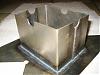
Well, as many of you know, I've been on a long journey with my "Super Datsun" and the RB26. I'm now working on the baffle design for the oil pan. Originally was I was going to install some rubber flaps similar to what is in the E30 BMW M3's, (the 4 cyl ones). Pictures for what those look like are here: http://www.brazeauracing.com/oilpan.htm My oil pan pictures are at the bottom. Two avenues I'm considering and am looking for input/experience. First is the traditional trap door style. First problem is finding commercially available trap doors, or even just the alum. hinge. Second is what shape exactly to design the baffle - i.e. the diamond/square around the pickup. How far, etc..? Second choice is similar to what is now in the LS2 oil pans,(Corvette C6's). It is a wall with a small opening at the bottom. This allows limited oil flow in both directions. It should be more than sufficient for normal operation - and when you corner, it will limit the amount of oil traveling to the other side of the oil pan, but will not completely stop it,(actually, no design really completely stops it besides the rubber flaps or a trap door with rubber around the outside). After my pictures are some pictures of a new pickup for the LS1 camaro oil pan - there are two designs which recently appeared, same basic principle. Any thoughts?

-
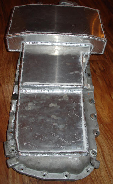
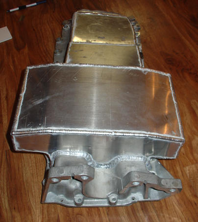
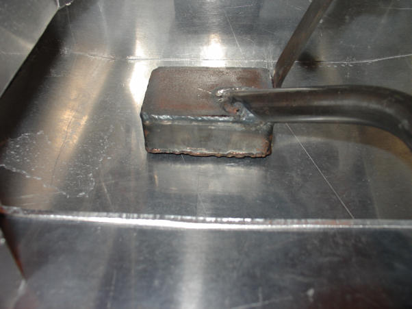
Well, another boat detachment taking students out to the Aircraft carrier steals another week away. Pulled the pan in this weekend to work on the baffle setup for the pickup. Required some time fabricating a brace to hold the oil pickup in the correct position so the baffle "walls" will be in the proper orientation to the pickup. Anyways, attached are some pictures of the outer portion of the oil pan - a friend of mine did the welding. The next set of pictures are of the inside - as you can see if you look at the joints - they are still rough. I will still have to smooth those out, then we'll weld where appropriate to ensure no leaks and a strong pan. I'm still trying to do more research on the actual baffle design. I found some info here: http://www.brazeauracing.com/oilpan.htm Or rather that is the "rubber flaps" I'm strongly considering using. They are used successfully in both M3's and in the RB26's,(Tomei utilizes them). If I use hinged plates,(trap doors) I want to procure commercially available ones but can't find any. I did contact this site and they can sell me the "balls" they use: http://www.billetfab.com/pans.htm If anyone has any pointers to baffle design or guidelines - I'm all ears! Once that is finalized, I'll make another cover with holes to help drain the oil, (and reduce foaming) which will go on top of the baffle but allow the pickup to go down in. In other fronts, I cleaned all the individual suspension components and I now need to sandblast and paint,(the parts cleaner took off some of the paint). Last, I have a few bearings which need to be replaced and one of the two rear tokiko struts was toast - minimal compression damping, so that needs to be replaced. I'll have to check the fronts. Moving along, moving along....
-
1/4" I was trying to make it as close as I could w/o putting it too close. I didn't really have much guidelines to go from,(for how far) so we took a 1/4" piece of aluminum and put it on the bottom of the pickup, then put the flat bottom of the sump on top of that and then tacked it in place, (and then removed the 1/4" piece of alum. stock used as a spacer). If you look closely at the mock-up pictures with the white cardboard, one shot which shows the pickup from the side/underneath the bottom of the sump,(has the elmers sticker) shows the approx. distance. In the end, I still need approx. 1/2" of oil in the bottom of the sump because the tube running down into the "pickup" box sits just above the mesh screen by about 1/4" total at the highest point. I'm still looking at some other options to lower the actual pickup down towards the mesh - such as extending the "tube" down to an angle flat with the mesh, taking up most of the remaining 1/4". Let me see if I can find a picture of the pickup itself... I can't find one which shows what the tube inside the "box" of the pickup looks like. I still may re-design the pickup itself. Sorry - long answer to your short question, but its still bothering me. -Bob To further muddy the waters, here is an article which talks about oil pans. In it, it references that all pickups in the test: "Pickupclearance on all three pans was 3/8 inch." http://www.circletrack.com/techarticles/ctrp_0603_oil_pan_design_windage_tech/index.html