Lazeum
-
Posts
779 -
Joined
-
Last visited
-
Days Won
2
Content Type
Profiles
Forums
Blogs
Events
Gallery
Downloads
Store
Everything posted by Lazeum
-
One way it would leak like crazy. On my particular case, I would have been unable to assemble it without understanding what is happenning (and maybe damaging the head gasket...)
-
indeed, you're correct 1.25mm is 0.049 inch. As I said, Damn units!
-
Thanks first for your support, I appreciate. I've never thought about the front cover that indeed would not match my block I will have to check what I can do. Worst case scenario, I'll ask the machine shop to take care of it also. All my measurements tend to believe block has been milled by 0.10mm, maybe that's something I can deal with (sand paper, a flat piece of wood and perseverance) Regarding the red line I expect to run, 6500 / 7000 rpm would be the max limit. With the help of Braap, we've designed the setup to be good with low end torque even if I sacrifice some hp in high rpm (Paul told me he achieved 267 crank hp on the dyno with 45DCOE and bottom end). So max hp would most likely occur around 6000rpm. Then back to my question, I've done some tests today and I've got some conclusions I have saved the previous used gasket which was fairly new so I've used it. - First I've cut the gasket around the front cover area to give some free space to use a gauge to check head position back to the block. - I've installed the head on the block with the old gasket. I zero'ed the position on the gauge. - I then removed the head, the gasket and reinstalled the head without any gasket. It gives me the answer I was looking for (or kind of). Felpro gasket changed head position by 0.87mm (0.034") so I definitively closer to 0.040" than 0.045" (too bad!) The conclusion is quite clear: I cannot use the setup as it is right now without changing something. Now I need to think about what to do, I think it will be quickly a matter of cost between new gasket (stock one at 1.25mm (0.060" 0.049") would be good with quench around 0.7mm - 0.027") or machining cost for pistons. I'm however wondering how compressing twice the gasket could affect the measurement. would a new gasket compress that much also? The used on one in free state was around 1.25mm (0.060") in between bores whereas new unit is around 1.40mm (0.055"). Anyhow, I'm not going to take any chance with new one as is. Since everything is already installed, new stock gasket would have also got my preference but don't forget I'm in Europe - it is not so easy to find parts for our Z's. I wanted also to try the shim method on the piston but my shim kit was too long to fit & I did not want to sacrifice it (it is shaped for Rebello cam clearance on lash pad) PS: Damn units!!!
-
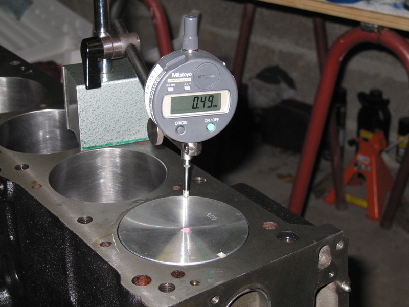
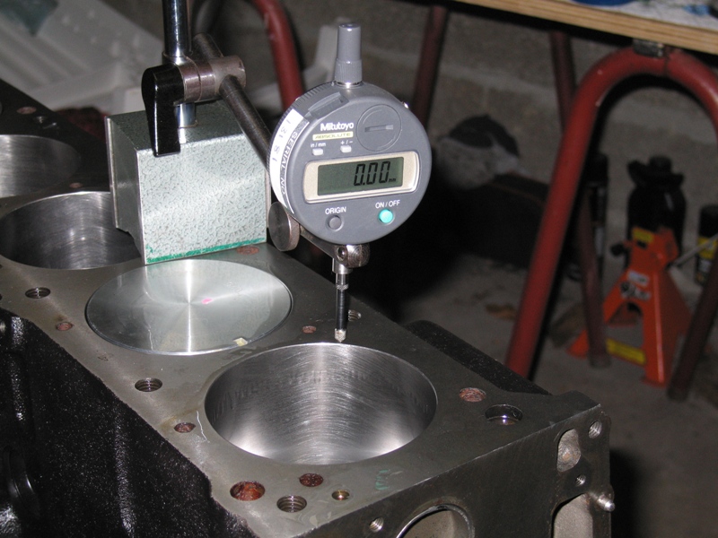
I'm in rebuilding process on my street L28 with P79 head. Setup is as followed: - F54 block, overbored to 0.30" (+0.75mm) & decked (unknown distance) - stock Crankshaft machined on rod bearing to -0.25mm (if that matters) - P79 head done by Braap with ARP headbolts, slightly milled down, port & polished with street Rebello cam - Flat top pistons & stock L28 rods with ARP hardware - All bearings, main & rods, are brand new I'm currently checking distance to achieve correct quench on this motor. Since the deck has been machined, I've assembled everything on the bottom end to find out. I end up with pistons popping up the deck surface at +0.53mm (0.021") - This has been measured, it is not a guess. The plan is/was to use Felpro head gasket. This is how I found multiple answers that make me creating this thread. I've heard compressed thickness to be 0.40" (1mm), Braap has measured them at 0.045" (1.15mm). There're tons on info about this topic on hbz but there're also many answers that contradict each other (quench distance, headgasket thickness, etc.). Pictures below show how I've measured deck height (it shows 0.49mm but I've been able to get 0.53mm afterwards) Following also Bryan's (1 fast Z) advice and recommandation for quench, clearance between pistons & heaad should be in between 0.022" and 0.025" (i.e. 0.56mm to 0.63mm) to get the best of the quench. The deal is with 0.040" gasket thickness, expected clearance will be 0.019" (0.48mm) - Engine will not work!!!! BUT with 0.045" thickness, I end up being at 0.024" - I'm right where I would need to be! So I'm trying to find a way to know for sure where I'm at. Since I found many contradictory information, I believe the only way to know would be to measure compressed gasket or piston/head clerance by myself on my engine. I foresee many options: - Install the head with and without the gasket and check some distances that would vary with the gasket. I believe this method would not be so reliable since a lot of variable can change from one trial to another. - Put a shim on top of pistons around quench distance (i.e. 0.023"), install the head with gasket and see if I can rotate freely the engine without being blocked because of piston+shim+head clearance. - Check gasket thickness with feeler gage once everything is installed - I would measure thickness but not where it matters at cylinders. What would you recommend? I'm confused - one mistake on this parameters and I can start a new rebuild in a few & trash my head. I then would need to find a way to correct quench distance. I've got 3 options in mind: get stock headgasket which seems to be thicker than Felpro gasket (1.25mm? I can see also 1.4mm?), mill the top of pistons to get the desire clearance or get a copper gasket at the desire thickness. Please help!

-
Nice numbers I'm wondering if it is truly your carbs + chokes that limit the power past 5500 rpm. Could it be the head or the cam instead? I'm being curious since I have to get new chokes on my setup, current 32mm are definitely too small, I'm hesitating between 34 & above. Looking at your AFR curve, if chokes were too small I would have anticipated AFR going on the rich side (no more air) which is no your case. Then regarding your mid range rich spot, we all have it (see post about Weber's around page 14 for AFR from me or Redbaron). With my new head (p79 ported with new cam from Rebello), I did not see it anymore (before the engine failed - lube issue).
-

NA 3.1L=>head & camshaft questions. No shortcuts, max
Lazeum replied to zredbaron's topic in Nissan L6 Forum
That's bad You obviously would have to perform a full root cause analysis to avoid future issues. Could it be a worn out oil pump? clogged oil gallery? oil plug that jumped out? ... I'll keep an eye on your thread. I'm rebuilding mine currently because of oil issue, my head (done by Braap) ended up being in perfect shape. Cam however was shot. -
DIY Fiberglass brake ducts
Lazeum replied to Lazeum's topic in Brakes, Wheels, Suspension and Chassis
Thanks guys. Didier, you know, weight is around 50-100g per part and it is way strong enough. so cheap sometimes is good Since then, I've added a grid. Paint will follow this weekend. I'll put picture of the finish product afterwards. -
I've never had to choose a turbo on my cars but I know that Honeywell is doing an awesome job to help you choosing the right turbo for your application. Based on readings, I would at least look at compressor map to pick up the right one for my goals. However, there're so many projects here that you can also choose based on users experience. Here's the link (you have basic, advanced & expert topics)
-
Weber jets??All who live for their triples please read this
Lazeum replied to datfreak's topic in Nissan L6 Forum
of course, you can ! -
Weber jets??All who live for their triples please read this
Lazeum replied to datfreak's topic in Nissan L6 Forum
Since you cannot change the delta between initial & total advance. You should target for appropriate timing for high rpm (around 34°, see service manual for instructions ). Ultimately, engine idles best with advance around 10-15° with Triple. To setup timing at idle, I run the engine with distributor loose and turn it until I reach highest idle rpm. However, I have the ability to play with timing on my distributor so I can do it fairly easily. and no big deal for double posts, it just makes you an easy target to tease -
Weber jets??All who live for their triples please read this
Lazeum replied to datfreak's topic in Nissan L6 Forum
We usually don't run any vaccum line with Triple. For mostly 2 reasons: pulse in one runner would provide erratic pressure at the valve, we put triple for power. In a perfect world, I would try to use vaccum (= high timing when intake pressure in below atmospheric pressure) since it should increase torque at mid range / mid throttle (=better streetability) & reduce gas mileage. In order to do so, we have to dampen pulses. One way to do it is to run a vaccum line to a small reservoir plugged to the distributor vaccum line. Pertronix & coil would just help timing accuracy & spark intensity, it should not impact the way the engine works but it should make it run smoother with better A/F ignition. If your L24 is stock besides ignition, you should be able to set idle at 800rpm easily. This is what I had with my engine. Durrag: At first I though the board was having an issue with double post then I read your answer. I love it -
Weber jets??All who live for their triples please read this
Lazeum replied to datfreak's topic in Nissan L6 Forum
That looks about right! That looks about right That looks about right I'm just not sure about float level but it would depend on your float type (brass or plastic) Air jet might be a little too big also. Idle jet at 50f9 might be too big (this is what I have on a modified L28), you might want to go to 45f9. you should follow the rule of thumb and make sure it idles fine with 1 to 1.5 turn using best lean idle method. But overall , the only way to know is to test on the road and see how it feels. It is a trial & error process. A wideband sensor would allow you to know in which direction to go (starting at 200$ for an Innovate MTX, there isn't any reason to do not follow this route) -
No, you just have to clamp them around the edge of the door with a rubber mallet. You need one for each door, One foot needs to be removed over the entire lenght to go around Z door shape. On the picture below, on the left, the original MSA seal, on the right the Twingo seal. See the way they have to be install, check also the thickness in free state and how much more they can compress.
-
I just wanted to share how I did the ducts for my airdam. here’s the how-to. It is not fully done yet, I need to trim them good & paint them. It was my first experience with fiberglass, I took whatever was available at the hardware store (no more thin fiberglass cloth, only thick coarse mat). It was actually a little bit too thick, it was not so easy to work with; it was too stiff so I had to cut small pieces in order to go around the geometry of the ducts. It is a process that’s quite messy with toxic products so appropriate protections are required: googles, gloves, mask are the minimum. Get some dirty clothes as well, if you ever drop some resin on your brand new pants, it is over. Other lesson learned during the process is to do not use plastic cup to hold the resin. Mine has melt in the process, process became even messier than it already was! Last advice, pay attention to draft angle or you may end up with extra work to do (like I did L; see the last steps below ) So first you need some products for fiberglass molding: - Some FG mat - Some polymer resin - Some hardener (often provided with the resin) - Some unmolding wax made specifically for FG. - A brush, a glass and a stick to mix resin & hardener together - Many gloves! - Acetone to clean the brush and the glass As an option you can also get some clearcoat for a better finish but since the ducts won’t be so visible, I’ve skipped this step to save some $$$$ & time. If I would have found some black clearcoat, I would have ended with some just because it would have avoided the painting process. Best practice would have required the use of a roller. Since it is not a structural part, I decided to stay with basic tools. The roller is basically a stack of small and bigger washers around a steel rod. I could have made one myself. If I would have to start over again, I would do one, I think. In addition to get the shape you want, you need: - Some plaster - Some spray can cap to give the round shape for the hoses - Some rubber bands to create a flange at the tip of the ducts - A sharpie - Some sandpaper to get the finish you want before molding (optional) To make the shape, I’ve thought & try several options, the best being for me some molding plaster: 4$ for 4kg. Depending on water quantity, you can choose the viscosity which is quite convenient. The hardening process is slow (30 minutes) so I had some time to get the plaster in shape with a sharpie. I’ve also used some spray paint caps to get a round shape for the hoses that would clamp on the scoop once done, a tube, big hose or anything round would also have worked but I took what I had. Just make sure hoses you’ll end up using would match the outer diameter. I’ve tried expandable foam also with no good result. The process now. 1. Get the airdam out of the car 2. Fill the brake duct holes with a piece of cardboard box cut to the shape of the holes and paint tape to seal them (to avoid plaster to go everywhere). Make sure you leave a small dish to have the plaster being able to locate itself. It will also avoid the plaster to move during the whole process. Pay attention to do not leave negative draft angle or it will be difficult to get the plaster out of the airdam afterwards. 3. Pour some plaster over the filled holes, give the shape you want for the duct and put spray can cap on top of it. Get the plaster roughly in shape. (I would recommend using gloves for this operation). This is the step where you need to most to think about draft angle if you’d like to unmold everything easily at the end of the process. 4. Let the plaster become a little hard (5 minutes?) 5. Start shaping the plaster with a sharpie, it should be still soft and easy to play with. With time it becomes harder (and hotter), you can then get a better finish, plaster starts to become brittle. 6. Let everything dry for at least 24h when you believe the shape is the one you want. You can also clean any excess around the duct shape with a wet sponge. 7. Since plaster is porous, once it has dried out, we have to cover it with regular wax. I have used a candle, hot enough (I used hot water) to have the wax soft. I have scrubbed the wax all over the plaster. I’ve done it twice to make sure plaster was sealed. 8. With a paper towel, I then spreaded all over the shape and all around on the airdam some unmolding wax. I’ve put 3 layers; each needs to dry off & to be polished prior to apply the next one. I put some up to the face below the side light housing since I will locate one of my bolt/rivet to attach the duct below to hide it once finished. 9. Now it is time for fiber glass work. a. Start by getting some small pieces of mat before having your hands full of sticky resin. I did not cut them with scissors to avoid having straight edges we could have seen on finished part. b. Once resin is mixed with hardener, start by spreading resin all over the piece you expect to build with the brush, be generous. c. Put 1 piece of fabric on top of the resin. Resin you’ve applied before will help the fabric to stick to the shape you’ve made. d. Apply resin on top of the fabric to mix it with the first layer of resin, tap with the brush to spread the resin thru the fabric & to remove any air bubble. e. Continue until you’ve covered the whole area. Go a little bit over it, you’ll trim the excess afterwards anyhow. f. Once first layer is done, I’ve installed some rubber bands to create the flange. g. Apply a second layer everywhere for strength, it will also trap the rubber bands in the resin. h. Let the resin cure for at least 2h 10. Next step is what happens when you did not pay attention to draft angle; I had to cut the piece to extract it over the airdam. 11. Next operation was the trimming of the piece freshly made. I’ve used a Dremel with a cutting disk. It is very easy to process. 12. For a good finish, I use the Dremel again but with a sandpaper grinder to smoothen the edges and any irregularities. 13. Following step was to fix the cutting operation with some more resin and FG mat to close the shape. Since I wanted a good finish, I’ve put some resin outside but also inside. You now have 2 ducts ready to be installed on the airdam to receive hoses. I will also install a grid to avoid rocks to go inside. To install the grid, I plan to drill little holes into the fiberglass and use some ties to hold the screen. I was also thinking about making the grid going thru some holes and to use some more resin to hold everything back together. Overall it is a messy process but it is quite easy to do. Cost was also quite ok, I might have spend around 50$ total.
-
Aftermarket Control Arm Failure
Lazeum replied to z-ya's topic in Brakes, Wheels, Suspension and Chassis
We also need to take into consideration the moment induced during braking by the pads. It creates a moment that would be transfered longitudinally. The spring perch & the compression rod are the 2 only paths for stress during braking. The single point or double bolt system will differ from the way the stress is going to be sprend. No bending moment would occur with 2 ball joints at the extremities of the rod whereas there's most likely some with stock setup. I would assume it would be very small based on design otherwise Nissan/Datsun engineers would have made the rod much beefier. -
it looks like a TVR Tamora with a roof.
-
Aftermarket Control Arm Failure
Lazeum replied to z-ya's topic in Brakes, Wheels, Suspension and Chassis
It is definitely a poor design. This control arm is supposed to work in compression/traction mode + side loading due to compression rod. It requires high section inertia which the flat plate cannot not provide. Risk is to see the arm bucking under load (with stab bar helping in this way). In addition to that, the ball joint is making the outer side quite stiff also, compression rod ear is also making the flat part stiffer next to ball joint which pusses stress even more the failure point. You can also put in the equation the material properties of the metal. With the welding operation being close to the weakest point, it probably does not help. Either except if you quench the part right after to avoid metal to cool down slowly. Material properties are probably the lowest at welding location. -
During a WE with the Datsun club in France we had the opportunity to all exchange our cars to drive every Z we could. Since they're so many parts you can swap, it was hard to feel 2 cars behaving the same. Roll bar is also one more big contributor of handling. Mz feels quite ligh but super stiff to drive. Power is important but noise that goes with is also important. My dad was having a z3 3.0l @ 230hp, car was powerful (as much as my Z) but it was feeling not a good as the Z. One is smooth and quiet, the s30 is raw & brutal in comparison.
-
I had the same issue, it stopped working with no reason. I fixed it by changing the address with a different provider. It now works well. It might be worth a try, at least to check if it helps.
-
I've finally ordered some new pistons at +0.030 in. (+0.75mm). Those are ITM units with new rings. Block will then be rebored, surfaced & honed. Price was very fair (200$ for the set) so even if situation was not that bad, it seems safe to follow this direction. Since my current pistons are in very good shape I might even get some money back with them at some point anyway. Thanks all for your comments & help.
-
I think it is a safe move. I'm leaning torward the same option... I need to find pistons then. What was the source you've been using for the pistons? So far, the only source I've found with 87mm pistons for L28 is MSA with forged Ross unit, quite overkill for my application (and $$$!) Is there eventually a Mahle pn# that could match? It might be the easiest route for me since a friend of mine is sellling the brand.
-
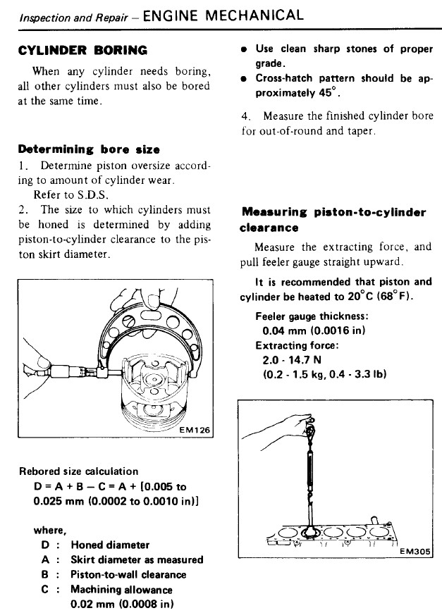
Thanks for your answer I'm back home, my first move was to check "how to rebuild your Datsun OHC Engine". Page 66, I can read: So with my 0.080 mm, I'm right where I should be However, I've surfed over the Internet to see what should be piston-to-bore clearance on other engines. Most of them are more around 0.0015 max. Ok, it is not a Datsun engine but the recommended clearance is most of the time below my measurements. So back to Datsun Service Manual, here's a copy. It is not in accordance to what the book mentioned above is stating. Is there something I don't understand I'm still confused - but I start to feel better!
-
I'm in the process of rebuilding my L28 engine since some lub issue occured and destroyed the head. Engine got contaminated with metal chips so I took it all apart to inspect & clean everything. Bottom end is F54, Flat top (+0.50), stock crankshaft. Mileage since last rebuild is small; less than 10k miles; pistons look new, no sludge anywhere. I've dropped the engine to a machine shop this week. Crankshaft needs some grinding & block needs to be honed (probably due to contaminated oil). It happens diameter difference between piston skirt & cylinder bore is measured at 0.08mm (0.0031â€) Checking service manual, I found that it should be: Bore diameter = Piston skirt diameter + gap – 0.02mm Where: gap + 0.02mm = 0.005 to 0.025mm => gap = 0.025 to 0.045mm Ring gaps with top ring was at 0.50mm (0.020â€) – Seem too big to me according to Service manual & “how to rebuild L engine†book. So I’m basically out of spec. My conclusion is I need to rebore the block and change my pistons with 0.040†overbore (+1.0mm) to do it right I see 3 options, budget is tight but I want to do it right: - I keep what I have – I just ask for honing & new rings. It is most likely the cheapest option but it doesn’t look like a wise decision based on comment above. - I source a set of 87mm pistons set – besides black dragon, I haven’t found what I’m looking for. I’m not even sure they are flat tops & I question the quality. - I find an old block & I rebore it to 86.5mm to match my current setup – it is hard to find though for a fair price here in EU. What’s your opinion? I am that far out from spec with my current setup?
-
This thread is old but I've got one question which is not worth opening a new one. My engine is now torn down, I brought it to the machine shop this morning. I believe previous rebuild was not done right: cylinder bores honing marks are gone, there're vertical markings on every bore (very light, I can't feel them with fingers), ring gaps are too big, piston skirts have scratches also, etc... Anyhow, My question is very simple. I've removed the oil plugs on front & back sides but I still see something which looks like a plug, I'd like to know what is it? A valve for oil pressure? Should I remove it before machine work? Thanks in advance for help. To answer the previous post, I decided to stay with pressed-in inserts (given by Braap with the new HF pump )
-
Weber jets??All who live for their triples please read this
Lazeum replied to datfreak's topic in Nissan L6 Forum
You better do a full report of your feelings with MJL I plan on doing it in the future. I'm running a Mallory Mnilite dizzy with Mallory 6AL CDI box. It allows me to get good idle and total advance but it is a pain to tune right and very time consuming... And I have no vacuum advance, I think it is bad, there's probably tons of torque to get back at part throttle & better economy during cruising.