Six_Shooter
-
Posts
1471 -
Joined
-
Last visited
-
Days Won
2
Content Type
Profiles
Forums
Blogs
Events
Gallery
Downloads
Store
Everything posted by Six_Shooter
-
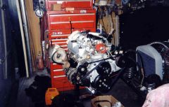
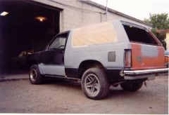
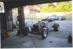
From the album: Typhony
This is how it looked after a few tweaks, and for most of the time driving it. -
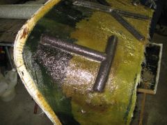
From the album: Typhony
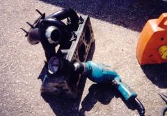
Right header, with crossover fitting complete, and smoothed out by home made tool. -
From the album: Typhony
Left header and crossover painted. -
From the album: Typhony
Mocking up turbo placement while building the headers. -
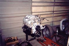
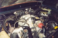
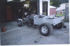
From the album: Typhony
The Franken60, shortly after final assembly, still a way to go. -
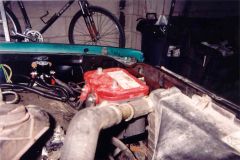
From the album: Typhony
New battery tray installed. -
From the album: Typhony
Custom battery tray to relocate to driver side. -
From the album: Typhony
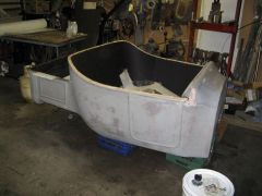
This is shortly before full primer and paint. some final blending at this point. -
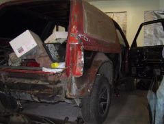
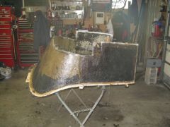
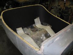
From the album: Typhony
Cut both quarter panels completly off the Jimmy as they were both pretty bad. I tried patching at first but became more of a mess than full replacments. -
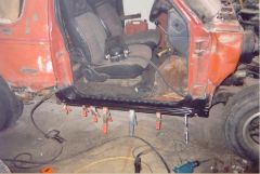
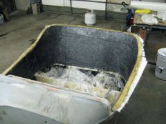
From the album: Typhony
Part way through the body work. -
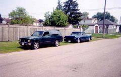
From the album: Typhony
This is a nice picture of my Jimmy shortly after I got it on the road, with the 1970 Chev pick up. -
From the album: Par-T
this is one of my favorites pictures. It has both the T-bucket and the '70 Chev pick up in the background, that is too much fun to drive. -
-
-
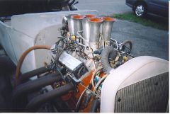
From the album: Par-T
Mechanical injection. -
From the album: Par-T
A day we were trying to get it running. Mechanical injection is not easy to get to run right. -
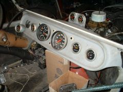
From the album: Par-T
Dash of the Par-T. -
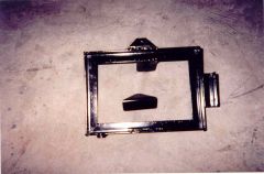
From the album: Par-T
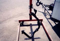
Added some reinforcment. -
From the album: Par-T
Removed from the body and 'glassed on the back side for more strength. -
From the album: Par-T
First layer of 'glass on. -
Would be nice to see more detailed pictures of that, since it looks like a short set-up (hight wise I mean), and places the front axle outputs in an area in relation to the engine itself that would work well in an S30 (and similar) chassis. The Cyclone and Typhoon used a set-up that is very much like what a 4WD truck used, just that the transfer case worked full time, instead of having that lever and vacuum actuated front diff. It's bulky, and would be too bulky IMO to fit in an S30 (and similar) chassis. I can take some measurements of how tall the engine and drivetrain clearance is of the S-series, when I get home, but it's tall, very tall in comparison to a car. If you did want to go this route, you could use an AWD transfer case from an AWD Astro van. This was my plan when I was going to convert my RWD Jimmy to an AWD (I had a 4WD frame I was going swap for my 2WD frame). The Astro van AWD transfer cases are much easier and cheaper to come by than the Sy/Ty transfer cases, though still not a dime a dozen. I think to fit best in the narrow Z engine compartment a longitudal engine layout will be needed. To turn the engine 90* would require basically rebuilding entire front unibody section and probably using the donor inner sheet metal to do so. Then as in most FWD/AWD layouts using a conventinal inline or V engine a lot of that weight is forward of the front axle, where as mentioned there doesn't seem to be a lot of real-estate anyway. There would be lots of space behind the engine for turbo(s) or other equipment. The hubs could be adapted from a FWD or AWD car, and if you're not opposed to changing out the struts (would you really be if you're going this far?), then you could adapt that entire set-up from any car that has the right overall hight, and other parameters that would be important, like knuckle mounted tie rod arms, for the steering. If it's rear steer (most likely with a FWD), then in most cases the knuckles can be swapped side for side to place the tie rod attachment at the front. This is assuming of course that the stock or similar layout for steering can be retained.
-
Traction Control using abs sensors
Six_Shooter replied to Chemicalblue's topic in Miscellaneous Tech
there are afternarket traction systems around, I've bee racking my brain trying to remember the one that looked simple and reported to work well. Yes, like most other sensors GM would probably be the easiest to adapt. The tone rings only need to be of a ferrous (magnetic) type of metal, so steel or cast would work. For a custom application steel would probably be easiest to use. The GM sensors when pulled from the rigt application would be very easy to mount. I know the mid '90s Cavalier and Grand Ams had a simple ABS sensor that had one or two bolt holes on a fairly flat mounting surface, that looked quite easy to retrofit. I'm sure there would be others that would work as well. It might be this one that I'm thinking of: http://www.racelogic.co.uk/ There are more similar systems out there. -
10mm? I could believe 18 or 19mm. There are also tools for doing this, in a very similar fashion, available from Snap-On and Mac, and probably other tool trucks as well.
-
From the album: Par-T
Another early shot. -
Traction Control using abs sensors
Six_Shooter replied to Chemicalblue's topic in Miscellaneous Tech
I've seen this discussed many times over, haven't seen a real viable solution, because it takes a comparitor circuit to monitor all points of interest, and then decided how much differnce is too much and send this signal, what ever that may consist of (determined by your power controlling device, I.E. Haltech, ignition retard box, etc), to pull timing or power out based on how much wheel spin. If you wante dto get real trick, you could have a variable output (as long as the Haltech can support this), to pull more and more timing out if the initial isn't enough. The discussions have also consisted of what should be monitored and the best seems to be RPM , some suggest drive shaft speed and a non-driven wheel as a base. Depending on how sensitive the circuit is, just going around a corner could trip the circuit into thinking there is tire spin. For montiring the front wheels, depending on how the S130 hubs and rotors are set up, you might be able to adapt a newer rotor that has a tone ring built in. If it needs to be custom a tone ring could be made and then pressed onto the hub, into the rotor, or some sort of bolt in deal, that gets sandwiched between the hub and rotor, and places the tone ring close to the knuckle. Kinda like making a rotor hat from a very thin material, to then hold the tone ring. One possible problem is if your car is able to pull the front wheels or take a LOT of weight off of them, this can slow the rotation of the wheels and then make it seem like the rears are spinning, even though they have excellant traction. I wonder if some sort of first gear disconnect would be benificial here. Take a look into some aftermarket systems, you may find this to be a more viable solution. -
New Photo of the Z car doing a Wheelie
Six_Shooter replied to jnjdragracing's topic in Gen I & II Chevy V8 Tech Board
Do you find that works better than a Miller locker?