Chris Duncan
-
Posts
163 -
Joined
-
Last visited
-
Days Won
1
Content Type
Profiles
Forums
Blogs
Events
Gallery
Downloads
Store
Everything posted by Chris Duncan
-
 Have you looked at Enkei? I think they are the best bang for the buck, but they don't really have any pattern that's like the one in your pic. They easily compare in weight and strength to a Works but are 1/2 the price.
 -
I think this is your best guess. The bolts are continuous around the edge, on the SSR the bolts are only between the spokes.
-
trust turbo manifold that is not 2k dollars!!!
Chris Duncan replied to redzedturbo's topic in Non Tech Board
$400 for a turbo and a manifold? Maybe something has changed but I've never seen Japanese parts sell for that amount. Maybe it's just shipping from Japan? -
Look at the pinion tensioner adjustment. It's the really big nut with a straight slot adjuster. It's right by where the steering shaft meets the rack. Look at the nut to see if it's had a wrench on it recently. If someone has tried to adjust the play out at dead center it will be tight to either side. The rack could also be bent, not uncommon if it's ever been wrecked. Those are the two main things that can cause bind when the rack is tested off the ground.
-
trust turbo manifold that is not 2k dollars!!!
Chris Duncan replied to redzedturbo's topic in Non Tech Board
Another place they cut corners is tubing thickness. (Ebay) A $240 OBX RB26 exh manifold uses 1.5mm wall tubing A $700 Tomei uses 2.5mm wall these are both 304. Anything in the above $1000 range will be 321. 304 will handle factory level HP and maybe a little more, 321 will handle way more. Believe it or not there's a $150 RB manifold on Ebay that advertises as 321. Pretty doubtful... -
trust turbo manifold that is not 2k dollars!!!
Chris Duncan replied to redzedturbo's topic in Non Tech Board
With 304 SS that's probably $400 materials at a low volume price, if it's good which you would suspect a Trust would be then 321 which would be closer to $600. If you fabbed a one off it would probably take about 30 to 50 hours. You can see how it gets to $2K real quick. The link is already dead. A manifold and turbo for $400 is Chinese, obviously because of low labor costs. The welds will be suspect and so is the material. There's RB26 manifolds for $150 on Ebay. You could grind off all the welds and re-weld but is it really 304? And how much would it cost to have it analyzed? -
I would look at the specs on whatever clevis you use. I think just like rod ends there are several different grades (strengths). If it's supplied without specs then that's questionable. +1 on the 4040
-
New custom wheel from American Racing
Chris Duncan replied to str8pipez's topic in Brakes, Wheels, Suspension and Chassis
That's a large selection of sizes and offset, and the offset can be tailored. But only one choice of center style, hopefully they will expand on that. There's more than one dimension of caliper envelope. The easy one is the inside barrel diameter, the other is the distance from the hub face to the back of the spokes, and it doesn't look that large on these. When you run fixed piston calipers (as opposed to floating) they require more room, because the outboard piston(s) stick out more than a slider style which doesn't have outboard pistons. Most wheels are only set up to clear the more common sliders especially a wheel that gives up a lot of axial distance to the outer dish. -
Now I'm kind of wondering if I do have the P30-0061. They are out of a '75 280Z but they don't have this number, or any number with these type digits.
-
1/4" right there is quite a bit. Assuming a 12" rotor, that's 2.4 degrees. That translates to 1" at the strut top which is pushing or exceeding the limits of some camber adjustment setups. And it's going to change your kingpin axis inclination. Remains to be seen if it drifts or pulls. Something is bent. To find out which side get someone to measure a known good strut. You may have to get a measurement with the stock rotor since the rotor offset is probably different. That or measure with an angle gauge as already mentioned.
-
the 240-260-280 have slight differences but they are dimensionally the same and will all bolt up.
-
I have some but they definitely need rebuilding UK? that's going to be some shipping $$$
-
If you have exposed rafters in your garage you can lay a piece of tubing across them to distribute the load and lift the body onto the rotisserie with a come-a-long. The engine stand rotisserie has a weight limit of 2000 lbs but any more than a 1000 is going to be problematic as far as spinning balance. Probably unsafe to try to bolt in motor trans diff and then try to turn the car. I usually take the chassis off the rotisserie while it's still completely stripped, like after it's painted and before anything is attached.
-
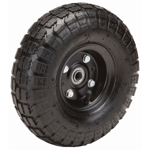
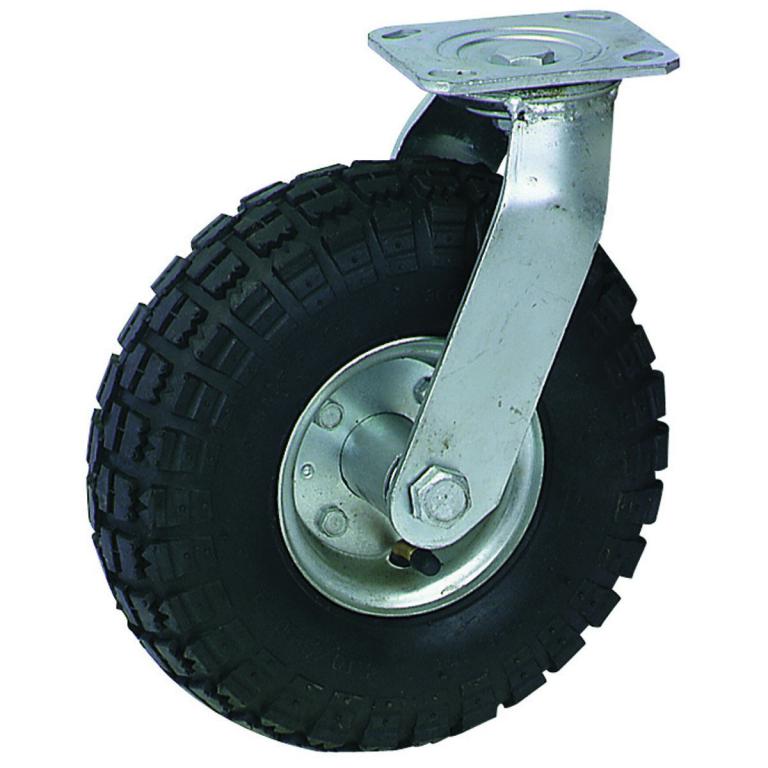
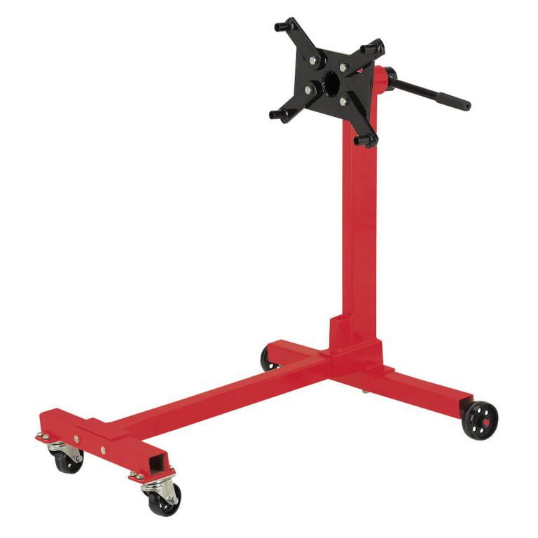
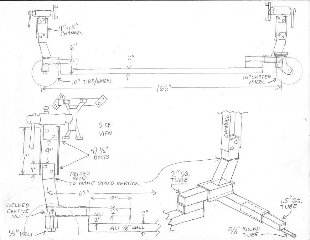
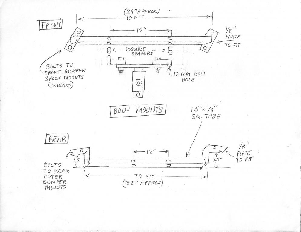
I consider a rotisserie to be a must have when it comes to a full restoration. When scraping off the undercoating, sandblasting, rust patching, and painting it's a lot easier if you aren't crawling underneath. It also much easier/ better to weld if you can maintain an optimum horizontal position. Rotisserie made from Harbor Freight engine stands. 2) Harbor Freight heavy duty engine stands 2) HF 10" pneumatic wheel / tires 2) HF 10" caster wheel / tires 1) 20' x 2" x 2" x .125" 1) 10' x 1.5" x 1.5" x .125" misc, 1/8" plate, 2" x 1/2" strip plate, 5/8" x 1/8" round tube Approx total parts / materials cost, $250.00 The HF engine stands come apart by unbolting. You remove the forward leg on each stand and replace it with tubing that runs the length of the car and connects the engine stands at either end. You replicate the captive nut assembly method so it can be dis-assembled. The engine stands are not wide enough to be stable with a car bolted up, you have to extend the sidewards legs outwards. The rubber tires were utilized to make this rotisserie roll on a gravel driveway. You could probably utilize smaller wheels and avoid the complicated 10" caster wheel mount (the most difficult part of the build). But you have to watch ground clearance. To maintain ground clearance with smaller wheels you could make the lower 2" sq tube go straight across with no spacers and raise the car for turning clearance by making the 4" x 1.5" vertical channel extender taller. The casters do not turn very well, you have to turn them in the direction you want to go then push the assembly. The vertical part of these stands lean backwards to counteract the weight of an engine. In order for a car body to turn smoothly the vertical support must be made completely vertical so the turning axis aligns between stands. Note the welded bend in the drawings. When fabricating the body mounts build the plates that bolt to the body, then bolt them to the body, then measure the 1.5" square tubing between them and weld it on while the body plates are bolted up to the body. In the front it may be good to put some washer spacers between the plate mounts and the body before welding. The weld distortion can make for a tight fit with no spacers. All the holes on the front and rear mounts can be drilled a couple sizes larger than the bolts to account for weld distortion. Or just hog them out if they don't line up after welding. Note the potential spacers where the body mount bracket bolts to the turning part of the stand. You may need spacers to clear the body / stand when it turns, and the mount bolts will have to be longer. I made the sideways extender legs to be removable so the engine stands could be used for an engine, but they could be welded on directly. The 1.5" sq tube could be substituted with 2" sq in that case. I also made the vertical 4" channel extender bolt on, this could also be welded directly. The channel could then be substituted with rectangular tubing but the vertical on the HF stand is an odd size. I would leave the center connecting piece as a bolt on so the rotisserie can be dis-assembled for storage. I've found that it's easier to just buy another engine stand than to unbolt and rebolt everything multiple times. Plus there's cases where you have an engine on a stand and need the rotisserie at the same time. The overall length of the rotisserie should probably be "to fit". Maybe make it a little long before you do any final welding. Or make the piece that bolts into the bottom of the stand longer and then cut to fit after the body is bolted up and checked to see that it turns 360 deg. Or just make the 2" sq tubing extend out the back of the stands. That way the stand is more universal for longer cars.

-
Lug Nut Recommendations?
Chris Duncan replied to nusevad's topic in Brakes, Wheels, Suspension and Chassis
Gorilla lug nuts. Very small outer diameter. Another option an internal hex lug nut. -
I've ordered wheels from Ebay and from Tirerack. Always with the caveat that they can be returned if they don't fit.
-
Advice/Opinion needed on this 1973 240z
Chris Duncan replied to LyleSweet's topic in S30 Series - 240z, 260z, 280z
Do not leave that dash out in the sun. Probably should also avoid temperature extremes. congrats, that's a nice Z -
I will post something ASAP
-
Advice/Opinion needed on this 1973 240z
Chris Duncan replied to LyleSweet's topic in S30 Series - 240z, 260z, 280z
That's a good deal for the condition. This is way less rust than what you find in Western WA. I would guess the only way you are going to get less rust is to pay 10K plus or go to Arizona and then you will have to ship. I would get this one, it's not going to last and it's hard to find them this rust free. -
They must have a crew of builders to build all the cars. Bet that is fun not having to worry about paint and body and getting everything lined up and perfect. Just slap it together and go.
-
The best Z grill is a custom Z grill because the way the hood opens it intrudes into the grill opening so you can't just bolt up a grill that's flush. Look at any Z grill and they all have a big gap at the top to clear the opening hood. This grill is hinged with linkages going to the hood hinges so when the hood opens it moves out of the way. Then when the hood is shut it moves back into flush position.
-
The rear subframe is going in quite nicely. Not near as much cutting out of the stock chassis as previously thought. One place that has saved weight and cutting of the body is to cut the short link inner mount off the sub frame and locate it to the body. This mount is very close to the body to start with, it will only be about 2.5" long as opposed to where it comes off the subframe it's about 9" long. So this also saves about 2 pounds. The vibration weights, all 4 rubber isolators, the short link inner mounts, and all ebrake cable brackets etc have been cut off and the subframe is now about 12 pounds lighter than stock. So since this is getting near to the weight of a scratch build tubing subframe I'm just going to go with this, it's a lot less work. Another positive aspect is that most of the chassis mods show up inside the rear storage compartments so very little will even be seen inside the cab. Cutting off the short link inner mount is kind of tricky. If left on the subframe while fitting it would require as much chassis cutting as all the other cuts combined. The bolt hole axis is not parallel to any of the 3 regular planes. So instead of trying to measure an axis that is angular in all directions just made a jig that locates the bolt hole. This jig does not interfere with the body, so no cutting just to locate a mount that is welded to the body. The existing chassis cuts go right through the square bracing that goes from the rear diff mounts towards the lower floor pan rails. Thinking to add some 2" square thin wall tubing here and also incorporate the front subframe solid mounts into that. Was thinking I should just weld the subframe directly to the chassis but leaning towards making it solid bolted, with two 10mm or 12mm bolts in each corner. A couple of setbacks though. Thought I measured carefully when choosing wheel size and checking coverage of the ZG flares. Had set the subframe/suspension assembly, with wheels/tires, under the chassis to check the track width. The ZG flares covered the tires with about 3/8" to spare. But now that I'm checking again coming up about 1" short. The first measure was 18 months ago, don't know where the difference has come from. Now I'm either going to have to source wider flares or add some extension to these. Really like the look of the ZG's so probably will go with widening them. The other problem is ride height. When locating the Skyline diff in the same place as the stock diff, and setting the axles parallel to ground, it comes out with 6" of ground clearance. Part of this is a larger diameter than stock wheel/tire combo, but since we need closer to a 3.5" to 4" ground clearance I may try to lower the subframe in the chassis, or more accurately raise it to lower ground clearance. This is pretty easy in the rear but the front end will be difficult. The front upper arm is already within 1/4" of the fender at full bump so the front 3rd link will have to be shortened by 1". I think it's better to lower this way than just adjusting some coil-overs downwards, it tends to preserve the geometry better. Will still need to do some of the lowering with the coil-overs but not anything extreme. A Bosch laser aligner/level is making this project a lot easier. One set up and the chassis is level in all directions, another single setup and the stock diff is located in 3 planes and axle centerline marked in 4 positions on the body. Previously this type of work involved a cluster*uck of fiddling with multiple bubble levels and 5 ft rulers taped onto carpenter squares, and then ending up with a suspect measurement anyway.
-
This thing is back on the front burner. The chassis is stripped and upside down on the rotisserie. Thinking for putting in the suspension going to bolt the chassis to the floor upside down, otherwise it's going to mean crawling around underneath and welding overhead. The suspension subframes are probably going to be 1.5" tubing either welded in directly or solid bolted. But haven't totally given up possibly using the stock subframes, maybe with a bit of lightening they will work. Don't see any reason to duplicate the factory double isolation of all rubber suspension arm mounts in addition to rubber subframe mounts. It's going to be just urethane inner suspension mounts and subframe solid to the chassis. The rear subframe weighs about 50 lbs. and a 1.5" tubing subframe will weigh about 25 lbs. Everything is close enough that it's all going to fit under the outer body. The closest it comes to hitting is the front upper arms where they swing upwards, it's going to be 1/4" below the outer fender. The front strut top centers are within 1/2" of each other from car to car. The R32 is 2" wider between the front frame rails and 5.5" wider track. The R32 front chassis clip is getting cut off behind the front strut/suspension towers and grafted onto the S30. The front of the R32 chassis clip will have to be narrowed in the front and possibly lowered. This works out because the front of the S30 is all rusted, and it also helps having the R32 front frame rails because they have a big curve to go over the front axles. This will also make the front upper suspension mounts easy because it would be complex to fab them onto the Z front towers. The rear is going to require some cutting into the area of the storage bins and this will be strengthened with some beaded sheet angled down behind the seats. Another thing that really works out is the rear struts are in the same spot from car to car, amazing. So the rear towers can be utilized where they are. Got some year old Toyo Proxes from Tirerack on sale. Went with a 245-35-R17. Racing a Z for a year gets you realistic about what size rubber works best. 245 is wide enough and the 35 profile will keep the car lower. Right now one of the sticking points is the steering rack. Want a manual rack with less than 3 turns lock to lock. The problem is the R32 chassis is RHD and the Z is LHD, plus the Z is front steer and the R32 rear steer. Was looking at flipping the Z rack over and building a pinion gearbox housing that would change it from front to rear steer but this won't work because of the 10 deg pinion gear angle, it ends up pointing the wrong way. Also the R32 is 29" between inner joint centers and this needs to be preserved to avoid bumpsteer. This is hard to find in a quick turn manual rack. All the custom racks I can find are like 4 turns. So if anyone knows of a manual, quick ratio, rear steer, LHD rack with close to 29" between inner joint centers it would be helpful. Something like 27" would work, it could be spaced out to 29". Two other things I've noted. The suspension changes from R32 to R34. They changed to an upper A-arm in front as opposed to the R32's rectangular upper arm. Guessing this is for more rigidity. And in the rear they changed the circular upper arm that goes around the strut to a half circle. Was wondering if anyone has thoughts on these changes? The front arm would be tricky to change, the R32 front tower suspension mounts are just not conducive to this. But the rear change would just be a bolt in.
-
Twin cam head for the L6 from Derek at Datsunworks
Chris Duncan replied to Derek's topic in Nissan L6 Forum
Have you given any thought to a plastic valve cover? After you finish this awesome project please make an aluminum 3 liter Z block. And when your done with that an aluminum RB30 block. Thanks. -
Lessons Learned - Crankshaft Repair Sleeve
Chris Duncan replied to Samurai7one's topic in Nissan L6 Forum
Just personal experience, admittedly haven't dealt that much with repair sleeves. But the ones I did didn't go well. They cut through with low miles on a dirt free street vehicle. I don't think the sleeves were stainless. YMMV. The reference to not driving the seal all the way in is also experience. Some Hondas are particular about that. I would think if you are going to line up the seal in a different place from where it's worn then you would prefer to go further in as opposed to less than full engagement.