zedman240
-
Posts
89 -
Joined
-
Last visited
Content Type
Profiles
Forums
Blogs
Events
Gallery
Downloads
Store
Everything posted by zedman240
-
Hope the silicone you used is the acid free one made for automotive use... it usualy eats through the paint then rust appears..It also happens when people use silicone to seal a leaky windscreen...
-
Wheel Show! Post your pics of you wheels
zedman240 replied to k3werra's topic in Brakes, Wheels, Suspension and Chassis
I'm running Perfromance Superlights (that almost weigh 21 pounds each!) in 16x8 with +4 offset an all corners with 225-50x16 tyres with standard suspension and no spacers, just slightly lowered but with lipped front and rear guards and have yet to hear any rubbing while driving so far.. 40 series tyres may be a bit small in profile. 50 series is as close as you can get to original rolling radius. -
Best part that made me laugh was when Jay Leno is interveiwing Eric Bana about the Targa Tasmania Rally....
-
In his description of the video, he says he's having some clutch issues. Don't think it's slowing him down at all!
-
What doesn't help sometimes is if the previous installer didn't install the locking cotter pins in right; it damages the edges on either side of the flat on the spindle pin making it so much harder to remove! Been through this ordeal only once...no more!
-
Not sure how hard it is but what about replacing the stock gauge internals with later more accurate gauges? I've seen tacho's modified with VDO internals..not sure with the smaller ones.
-
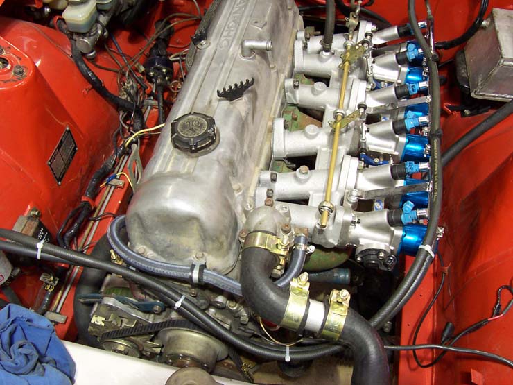
I did the same thing you are wanting to do except I used Weber bolt pattern throttle bodies. I just modified the original RB intake manifold and welded on Weber shaped plates that where water-jet cut from 8mm alloy plate. Similar to the previous post about cutting a G-Reddy manifold. They are very close from original. All up cost was around AU$300 but the trickiest part was setting up the throttle linkage. I have a youtube video of it when I had it running. They do make manifolds in Japan; if you can find one, bonus! I think MSD make a system to work with the original RB CAS because there is no spot for a distributor so you will have to make a system to run without one. I just ran 3 coil packs (but with a Wolf V500 to run it all) but MSD unit can run the coils instead of an ECU. Just have to research!
-
What are the advantages/disadvantages of having a welded rear diff?
zedman240 replied to dpuma8's topic in Drivetrain
From what I've experienced and heard, welded diffs make the car understeer a lot more so you would have to adjust the rest of the suspension if you prefer oversteer. Parking is real hard, and really abuses the half shafts unless you have a CV mod done. As you know how a differential works, when turning a small radius, the inner wheel travels a smaller distance compared to the outer. So imagine a locked diff; the inner wheel will be rotating the same speed as the outer wheel so say as you are doing a u-turn, you will hear the inner wheel "skipping" as the car is turning..like doing a slow motion burnout with that one tyre. Unless you have a full on race car, I would'nt bother. -
Got it running couple days ago...here's a quick youtube video of it running; just need to modify a distributor cap to keep the crud out!
-
Thanks to Ron and everyone else, I can finally say some success with the V500! Got it started and running roughly but fine. Still with the fuel map from the previous engine but when the exhaust is on, I can do some fine tuning on the road. I caught myself doing something that I think made it worse; not switching off and re-setting the ECU AFTER making changes to sequencing etc..Now with the ignition locked to 10', timing light shows 10' with ref degrees at 60'. All is well untill I get the refreshed L24 with lumpy cam installed and a good dyno tune and then I can post a video and some numbers. Thanks again for putting up with all my drible...hehehe.
-
Sorry to unearth an old thread, but I'm after the same info. Anyone know of a similar link or wiring diagram? Found a 2 wire sender and need to know how to wire it up. All my manuals are for a single wire.
-
Just curious if I should check sequencing of the injectors or does it not matter? Currently it's set to; Inj1 PO - 5,3,1,4,0,2 and pulse skip are all 5.
-
I'm 100% certain that there are a total of 4 wires going to the coil pack. The 3 Black with red/brown/orange and the +12V. I'm just curious why in the software it seems they have configured it for 6 individual coils where there are only 3. If you need me to take any close up pics of anything, let me know. That question "They used the 6 outputs to control 3 coils?" was a question and NOT how they wired it. In the loom there has only been those 4 wires to the coils and never 6. The RB engine was running with the wasted spark coil pack. When I bought the RB engine, somebody else took the original 6 coils off the motor. I'm sure I did reply to that but I think it was in some of the posts that got deleted. I can confirm, this is how the coils are wired up.. A12 Black/Brown wire - channel 1 (coil 6-1) A13 Black/Red wire - channel 2 (coil 2-5) A14 Black/orange wire- channel 3 (coil 4-3) And the +12V to all three coils. I'll post up pics tonight of the setup.
-
When I had the RB engine installed and running (with 120Kw at the wheels) and then removed it and installed the L24, the only part of the loom that I had to change was to just extend the wires going from the main loom to the coil pack. When the RB was installed, the coil pack was on the firewall and with the L series, it had to be moved near the front. I've checked about a dozen times to make sure I haven't re-arranged the wires but it's fine. Oh and the other mod was the removal of the plug for the CAS. Other than that, it remains the way Wolf (Robbie) wired it up. As for the wiring of the coils it is as follows; A12 Black/Brown wire - channel 1 (coil 6-1) A13 Black/Red wire - channel 2 (coil 2-5) A14 Black/orange wire- channel 3 (coil 4-3) And the +12V to all three coils.
-
Hmm..sent it a while ago to you Ron...never mind, what I'll do, I'll attach the file but rename it as a pdf file so it can be uploaded (doesn't allow any file type), just make sure you rename it to .ecu. Or keep it if you decide to run a Wolf V500 with a RB25DE with the same coils, it will get you off to a good start. This map is how it was running with the RB, without me playing with any setting as Robbie from Wolf set it up. I can give him a call anyway, or even better go around there to see him personally. He's about 30 mins drive away. Original_RB25DE.pdf
-
They wired up the current setup I have with the 3 wasted spark coils. They used the 6 outputs to control 3 coils? maybe that's what's confusing the #$% out of me...All I have done is removed the RB and installed the L24 with the L28ET distributor instead of the RB CAS and have kept the 3 coil packs and 3 chanel ignitor. Let me know if I'm missing out any imoprtant details that you need to know..I may be making it harder than what it is. I think you all deserve a medal for all of this after were done...
-
When I originally had the RB25DE installed, I had Wolf themselves wire up and tune the ECU. I'm confused now after reading the sticky, they setup the ECU to use 6 ignition outputs whereas I'm only using 3..Should the other 4-6 have the value of 255 to be turned off or left as they are? Don't worry about any appologies..Thanks..
-
When I installed the EFI system in my early 70 zed, behind the stereo area was a 2 pin plug with heavy gauge green wire but not connected to anything. That wire was there from the factory, already running to the rear where the fuel gauge and sender live. I just supplied that power from the fusebox to run the EFI pump mounted at the rear. There should be a wire already there; just have to supply power to it.
-
280-ZX, which models received R-180's vs R-200's?
zedman240 replied to FiveSeventyZee's topic in S130 Series - 280ZX
Manual or auto? Could be 3.5 or a 3.7... -
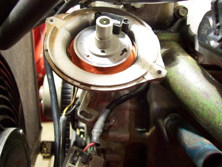
Been playing with the zed again over the weekend, and thought about the sync hole I drilled into the trigger disk and if it is in the right location. I posted a pic before but I can show it again. Looked at others in the Wolf thread and mine looks like it's 60' out. If anyone has the same distributor with the Wolf and the hole in the same spot, I would love to know the REF BTDC degrees!

-
You may need a longer thrust bearing carrier. Did you measure the height difference between the two clutch housings? if one is higher than the other, it has to be compensated in the bearing carrier. Sounds like it's not going far enough to dis-engage the clutch. Or a longer rod where the slave cylinder is. Just a thought.
-
With the CAS sensor for the RB engine, I opened it up and drilled the hole into the trigger disc and never used an adapter. It happened to be the one that couldn't be stripped entirely so the hole had to be drilled with the disc still in the sensor! Yes, I had a friend help with the mods to both sensors but in the previous pic, the distributor isn't at the #1 TDC location. I'm thinking now I may have installed the distributor drive spindle slightly out. I changed it to the slpined shaft when I had the engine out. I made sure I lined up the pin punch on the shaft and oil pump housing marks.. With the high res input, as you said, I won't bother. I'll leave it as it is. I'll email the map when i get home; I pass the time at work on the forums! hahaha. Thanks again RTz.
-
The V500 has been set up to use a CAS from an RB25 using all four wires plugged into it when the RB was installed. I thought they were virtually the same sensor as the L28ET dist so I thought just had to re-wire and that should be fine. But things don't always work out so easy as you like! I'm assuming it's only using the low res input but I'm trying to find where you can setup the high res input in the Wolf software..
-
Thanks for the help and you were right! I locked the ignition to 10' and rotated the distributor till it could start and run (barely). Took a pic of where the distributor ended up before it could idle. Didn't want to run it for too long as the neighbours wouldn't appreciate a zed running with only headers and no exhaust. When I have the next chance, I'll hook up a timing light and see where it's at and compare to the ECU timing. Another thing, found a write up on installing the Wolf on the zed, and was told not to use the pin 30 but pin 28. When I do that,there is no signal. Using pin 30 which works for some reason? I'll post a video on youtube when it's running later. Second pic is how it looks now. previous one was during assembly. Thanks again!
-
Just about finished installing the V500 onto my L24 after the system was running with an RB25DE and ITB's and now trying to start the engine, sounds like the timing is waaay out. I thought the CAS from a RB engine and a distributor from a 83 ZXT would be just as easy as a re-wire but I'm wrong! While cranking, sounds as if the timing is way too advanced; pops / farts and cannon sounds as the fuel is burned in the exhaust and that's as far as it's gone. Can't take the zed anywhere as it's still on jackstands waiting for tyres! Just wondering if anyone is running a similar setup to mine and can email me a fuel/ign map to try. I will have to modify some parameters but it will be a good starting point. Running ITB's, 83ZXT distributor, wasted spark coil pack (3 coils). Appreciate any help.