tioga
-
Posts
145 -
Joined
-
Last visited
-
Days Won
3
Content Type
Profiles
Forums
Blogs
Events
Gallery
Downloads
Store
Everything posted by tioga
-
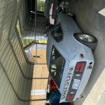
Fell down a Rabbit hole of mods to a good running car.
tioga replied to tioga's topic in Nissan L6 Forum

-
Fell down a Rabbit hole of mods to a good running car.
tioga replied to tioga's topic in Nissan L6 Forum
Have always used solar flux. I have a second regulator and argon tank but have never used it. I am curious about the difference in weld look with argon but have never bothered to try it. -
Fell down a Rabbit hole of mods to a good running car.
tioga replied to tioga's topic in Nissan L6 Forum
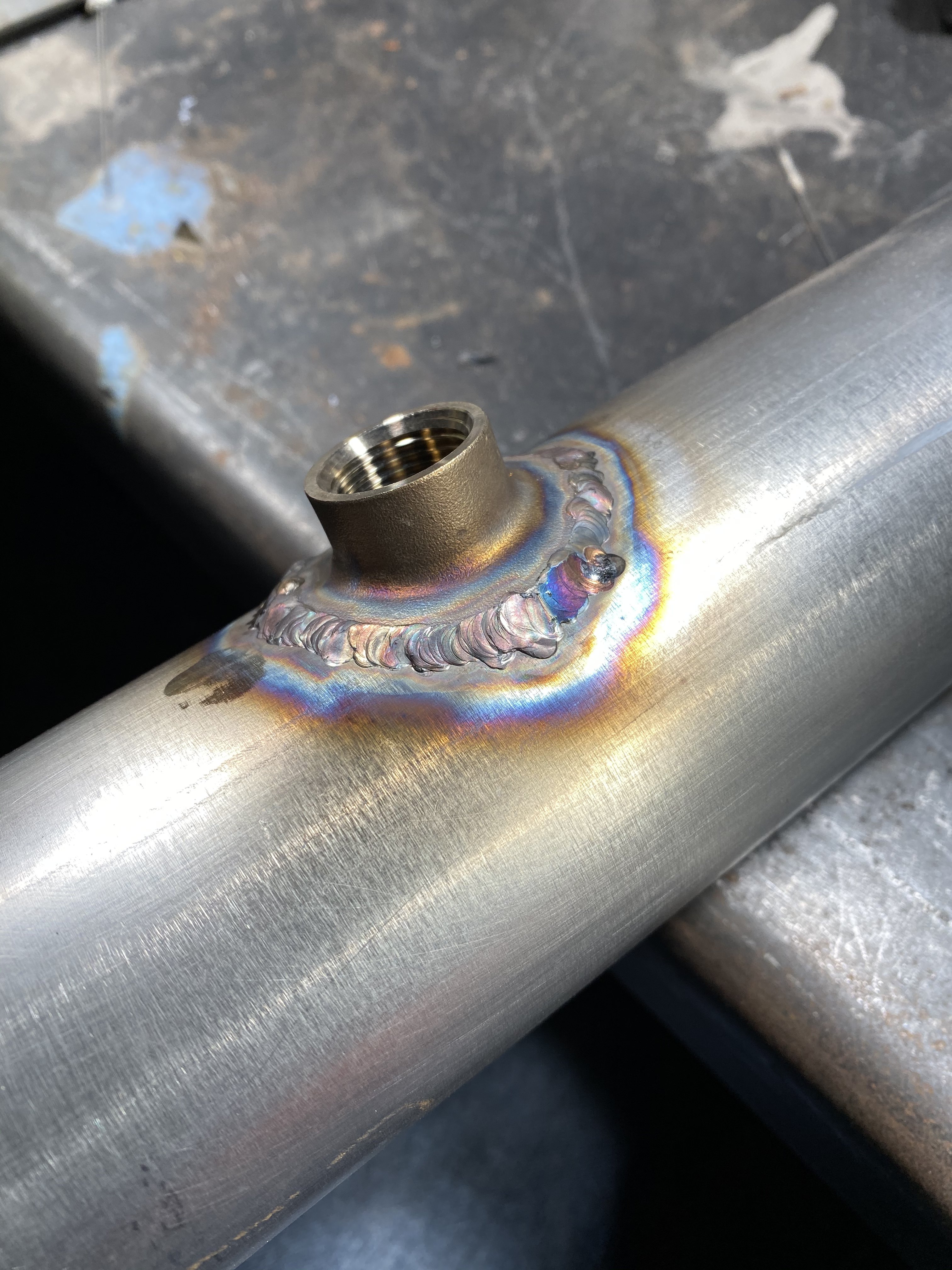
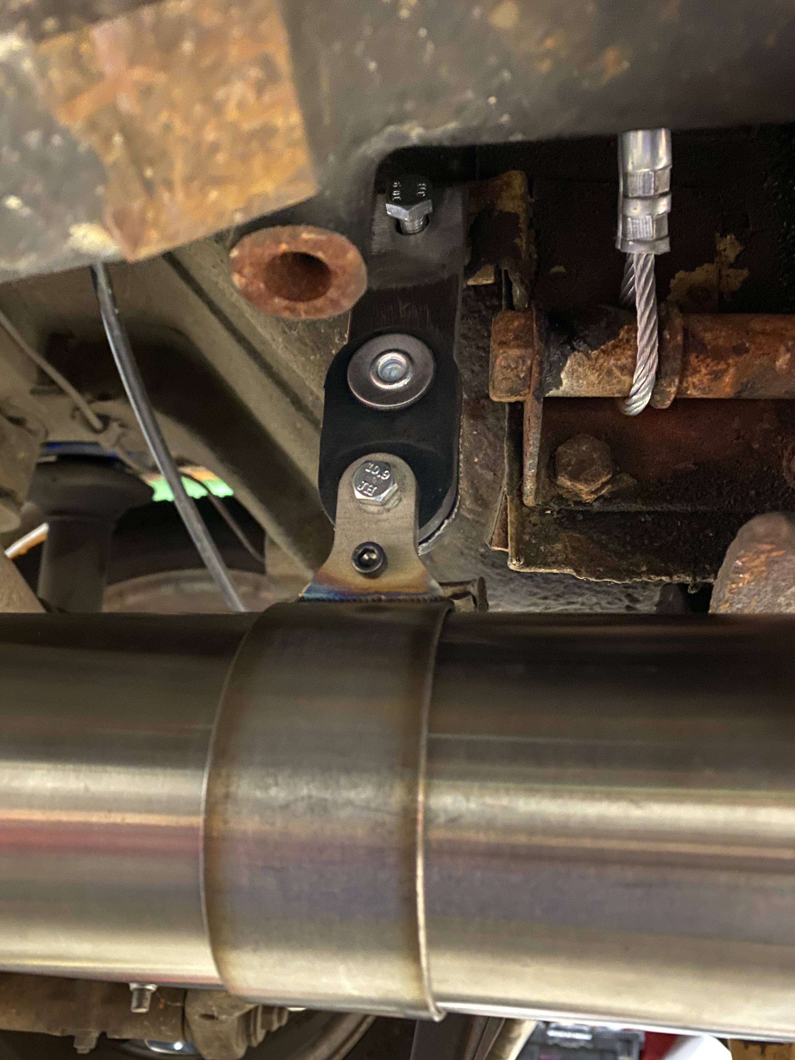
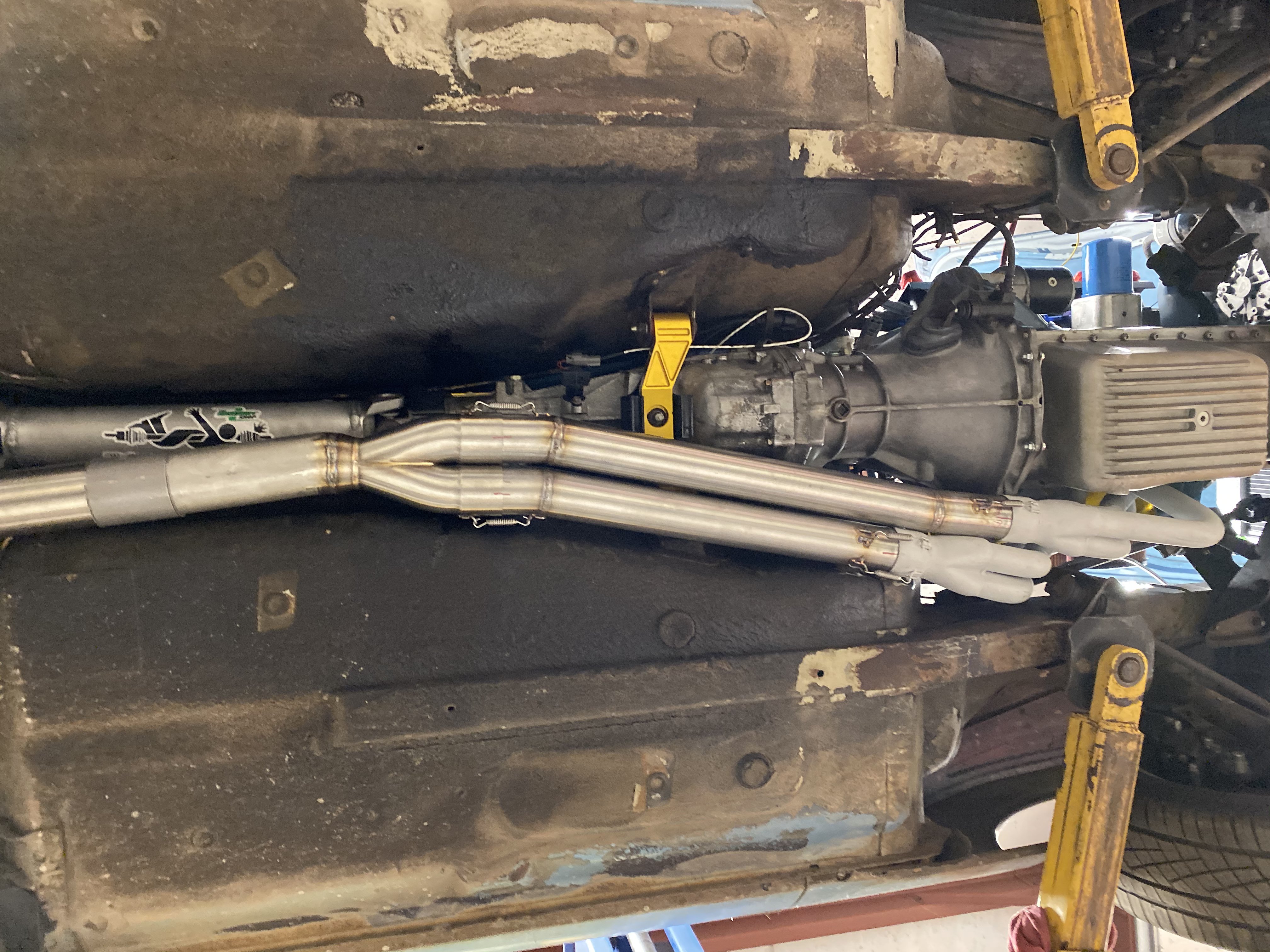
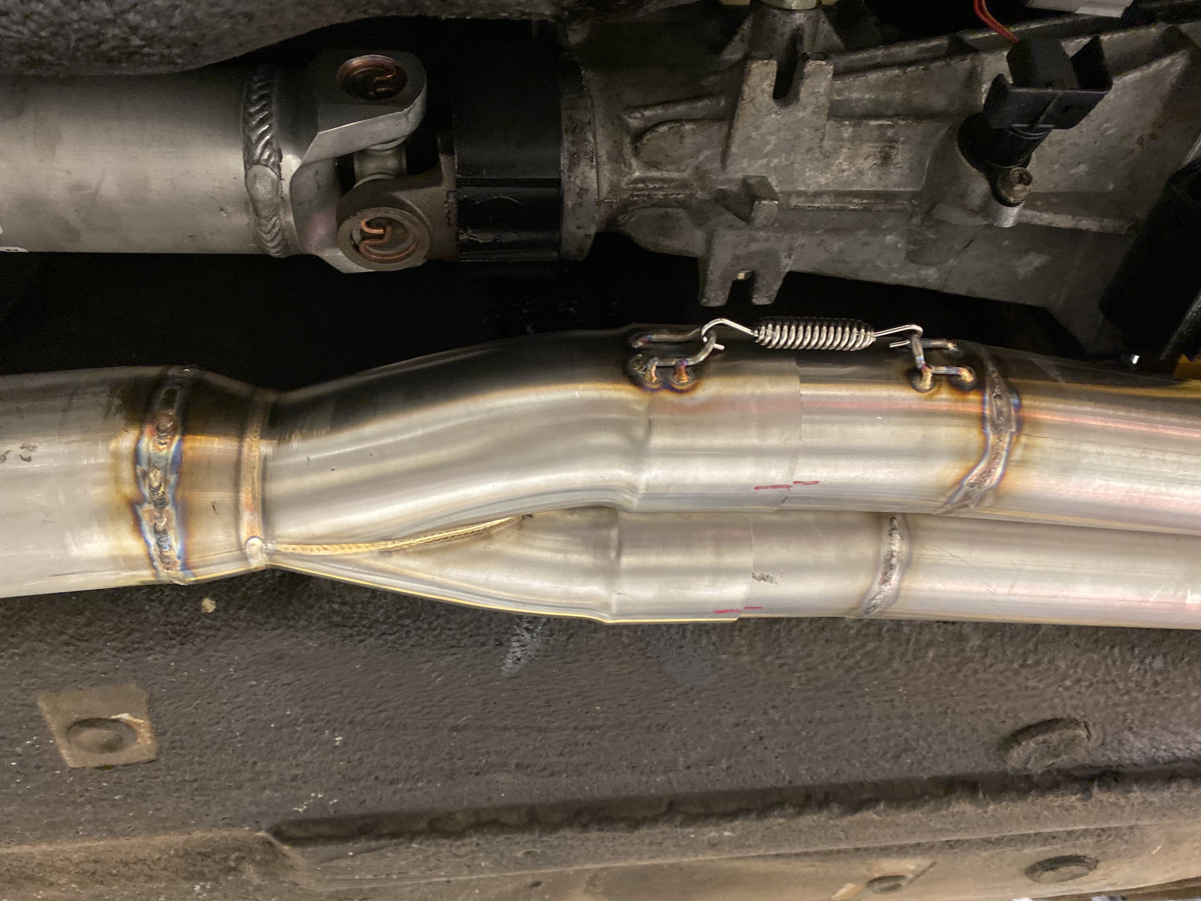
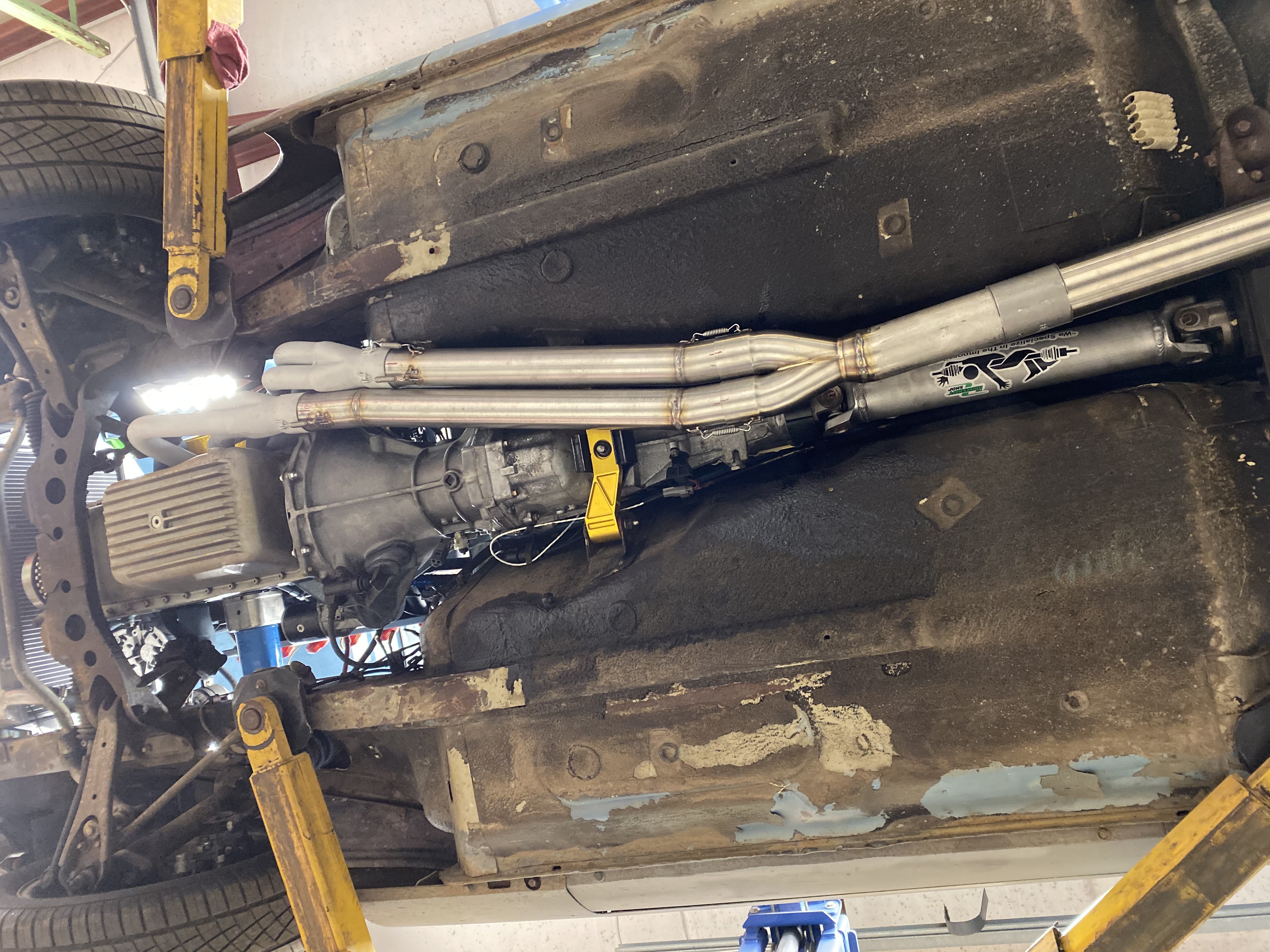
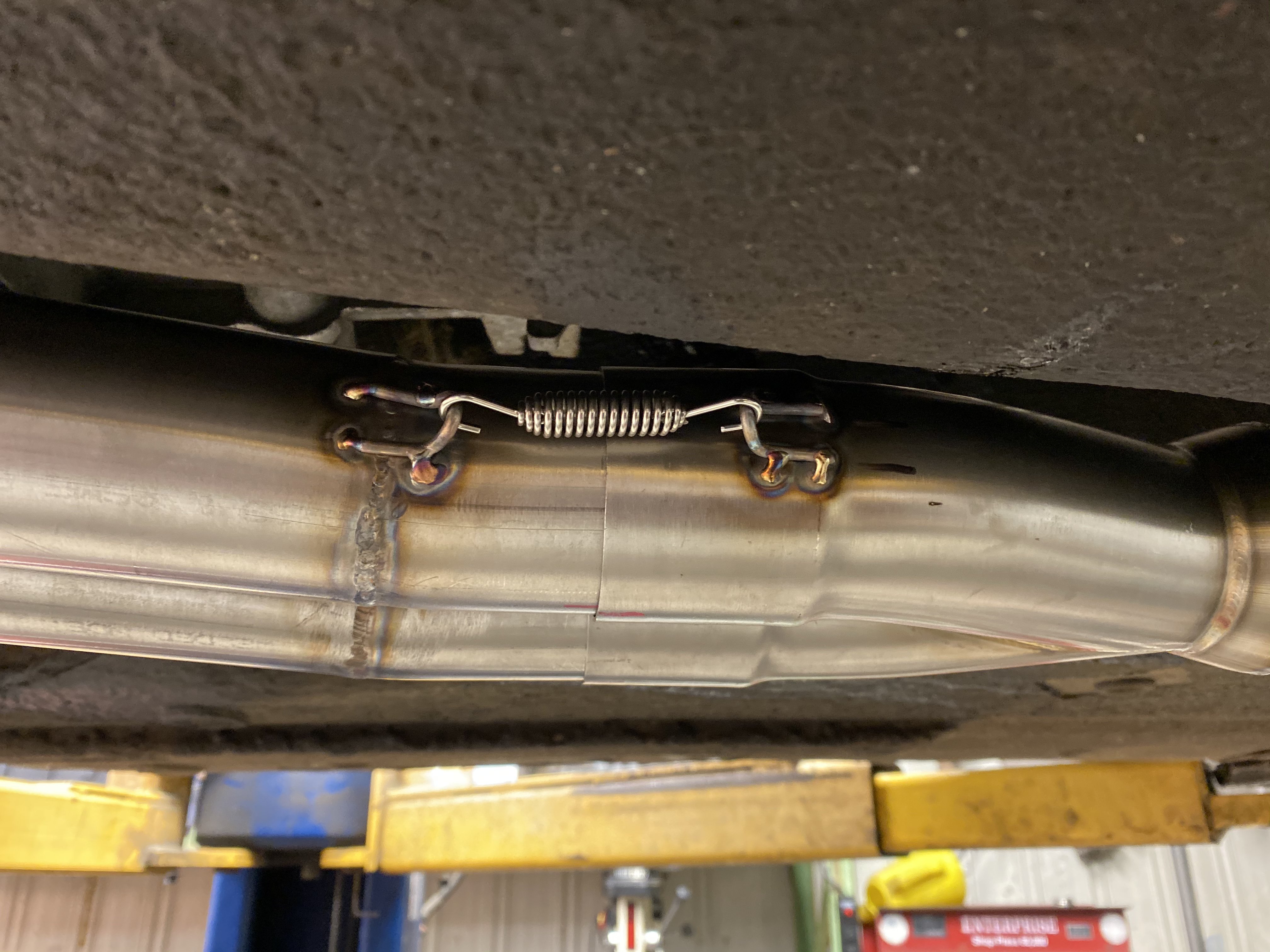
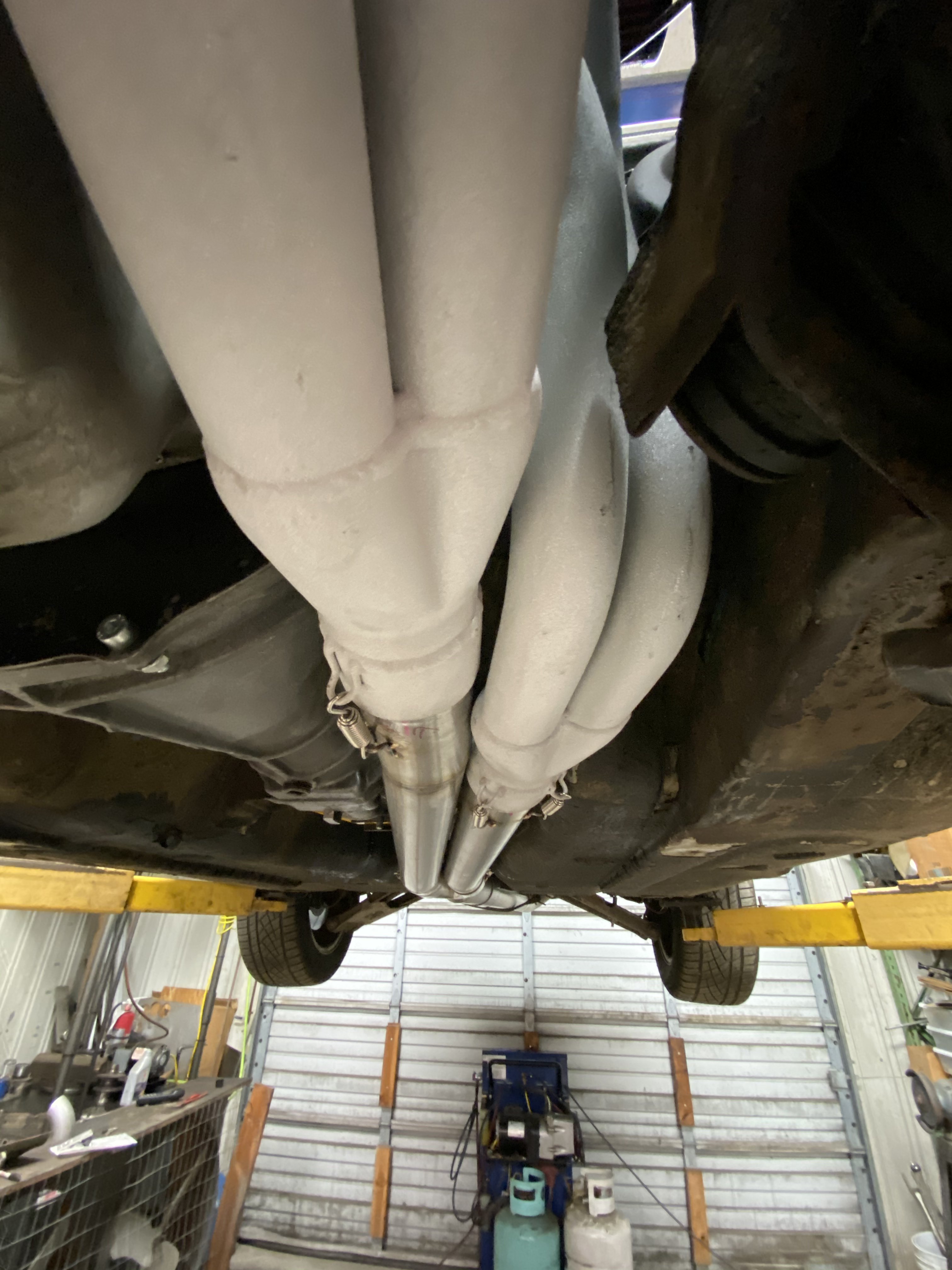
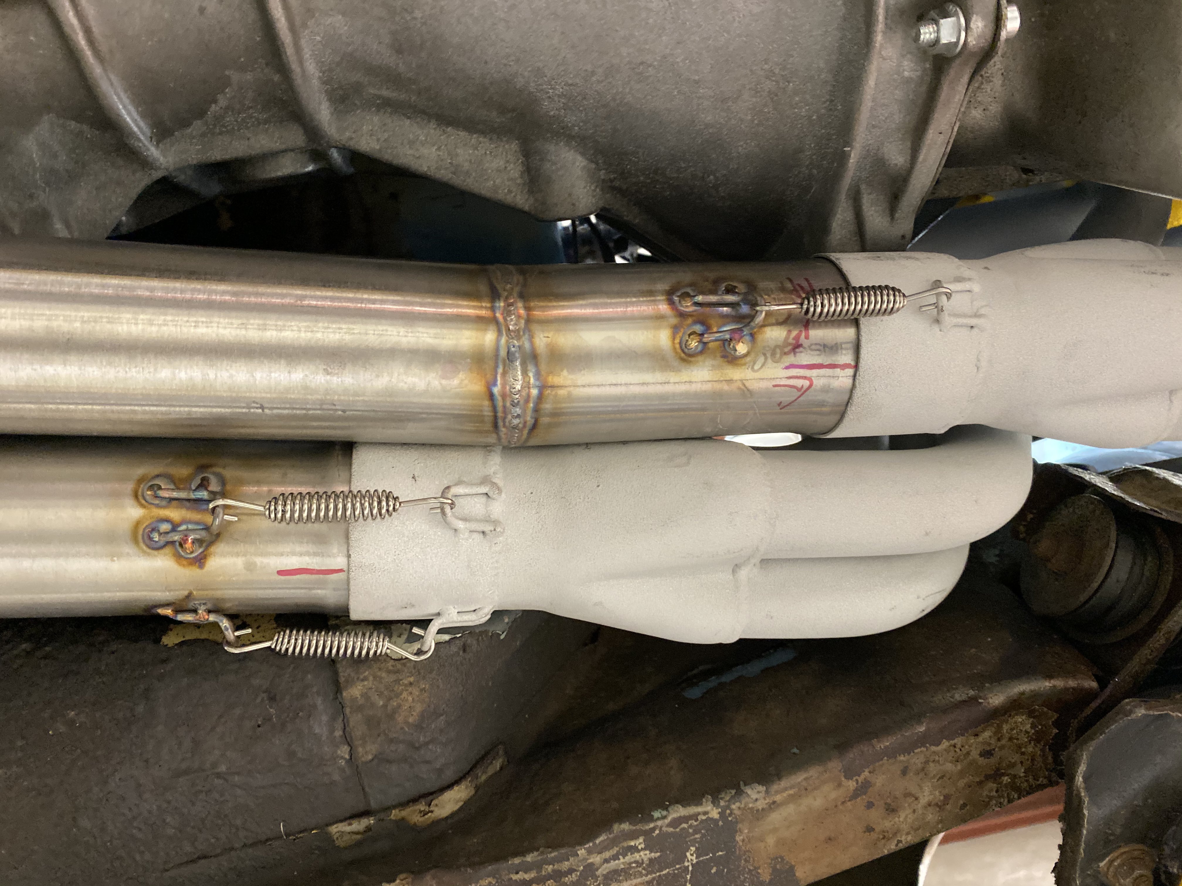
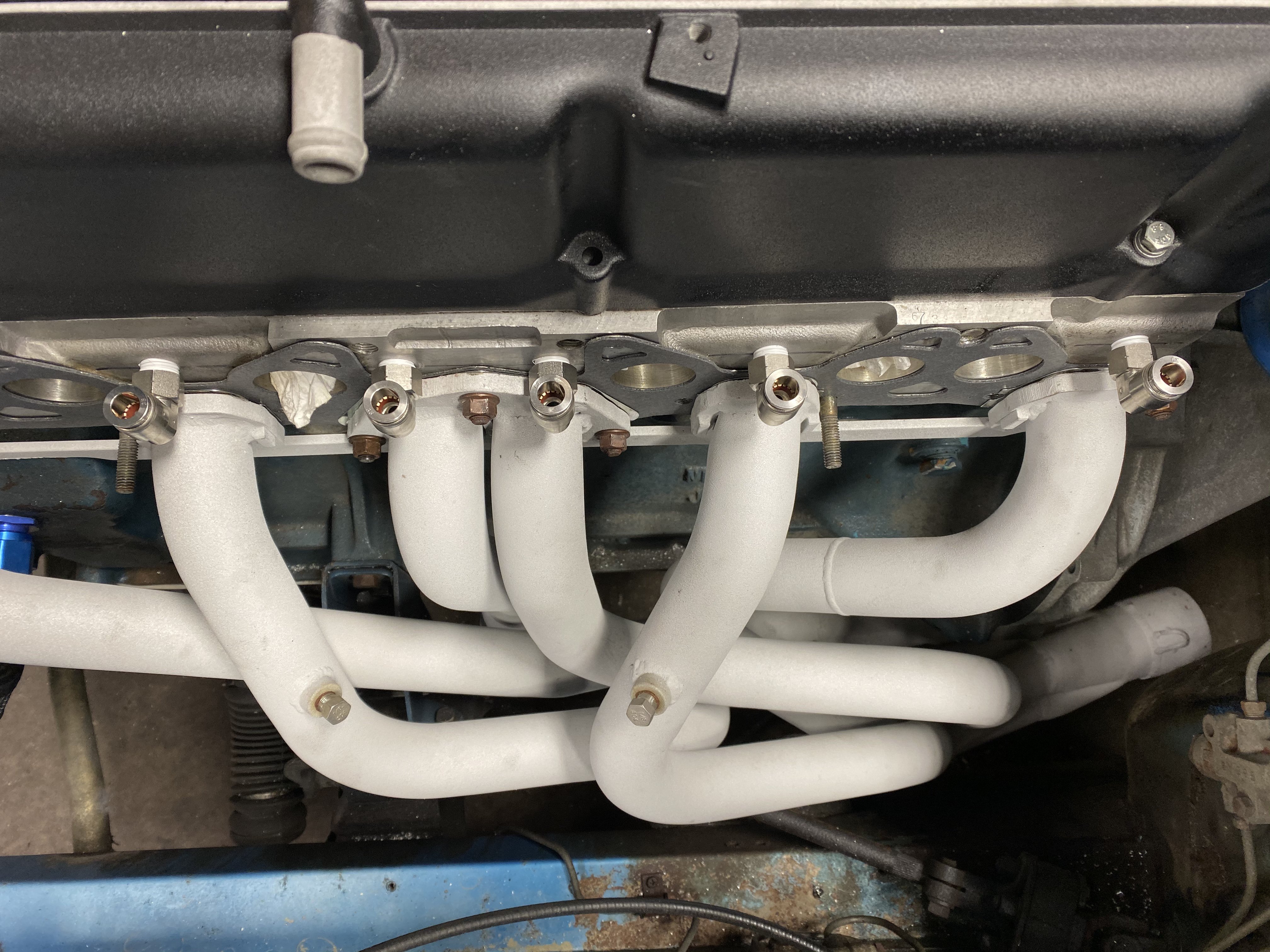
Made some more progress on the exhaust today. Some of my welds started to look better. Some did not. Should be finished this weekend for sure. What kind of welding table do people use when the exhaust sticks out 4’ One direction and 2.5’ perpendicular to that? I suppose they can weld pretty at any angle standing on their head. I can’t. I did do all my welds today without dipping my tungsten in the weld and that was nice. .
-
Fell down a Rabbit hole of mods to a good running car.
tioga replied to tioga's topic in Nissan L6 Forum
What cam sensor is that? Jeep? -
Fell down a Rabbit hole of mods to a good running car.
tioga replied to tioga's topic in Nissan L6 Forum
That is 350$ in fittings. -
Fell down a Rabbit hole of mods to a good running car.
tioga replied to tioga's topic in Nissan L6 Forum
Thanks Derek. How’s the VCT working? I haven’t checked in in a couple months. Is it up and running yet? -
Fell down a Rabbit hole of mods to a good running car.
tioga replied to tioga's topic in Nissan L6 Forum
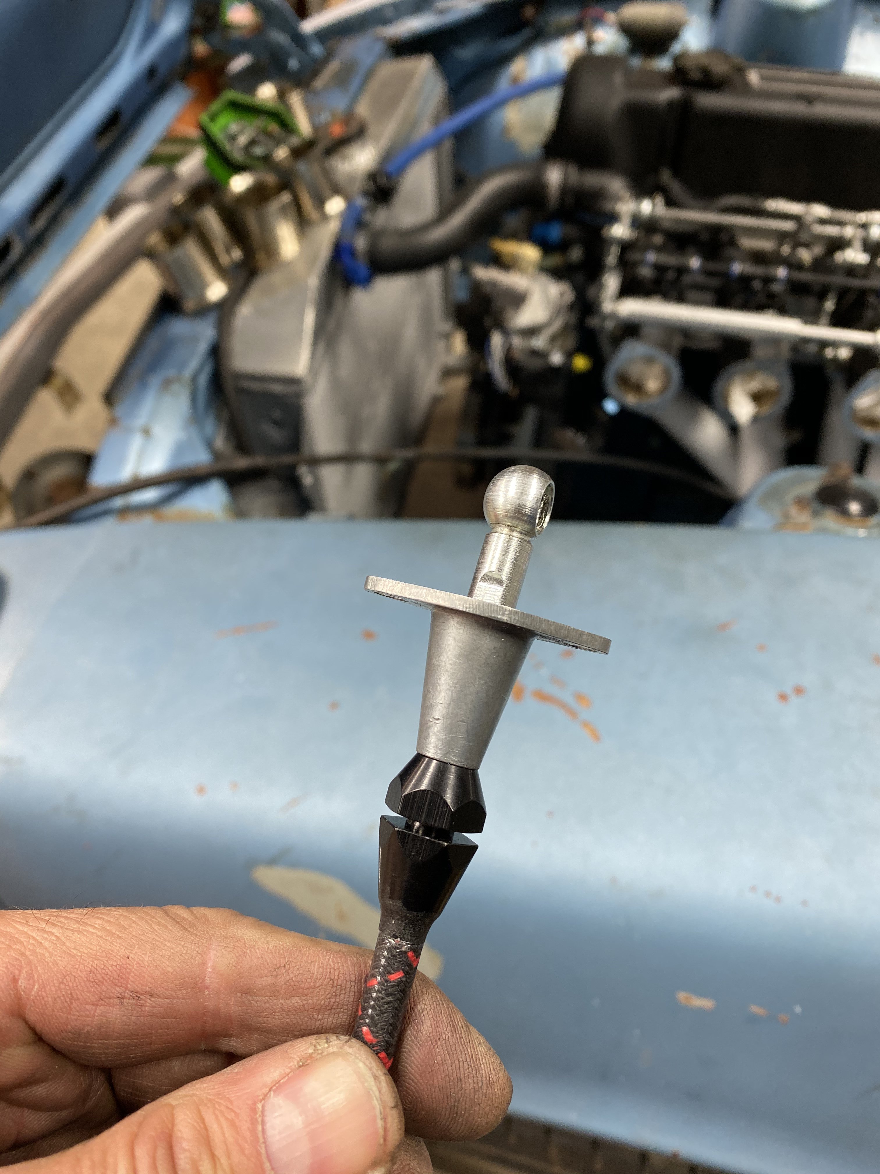
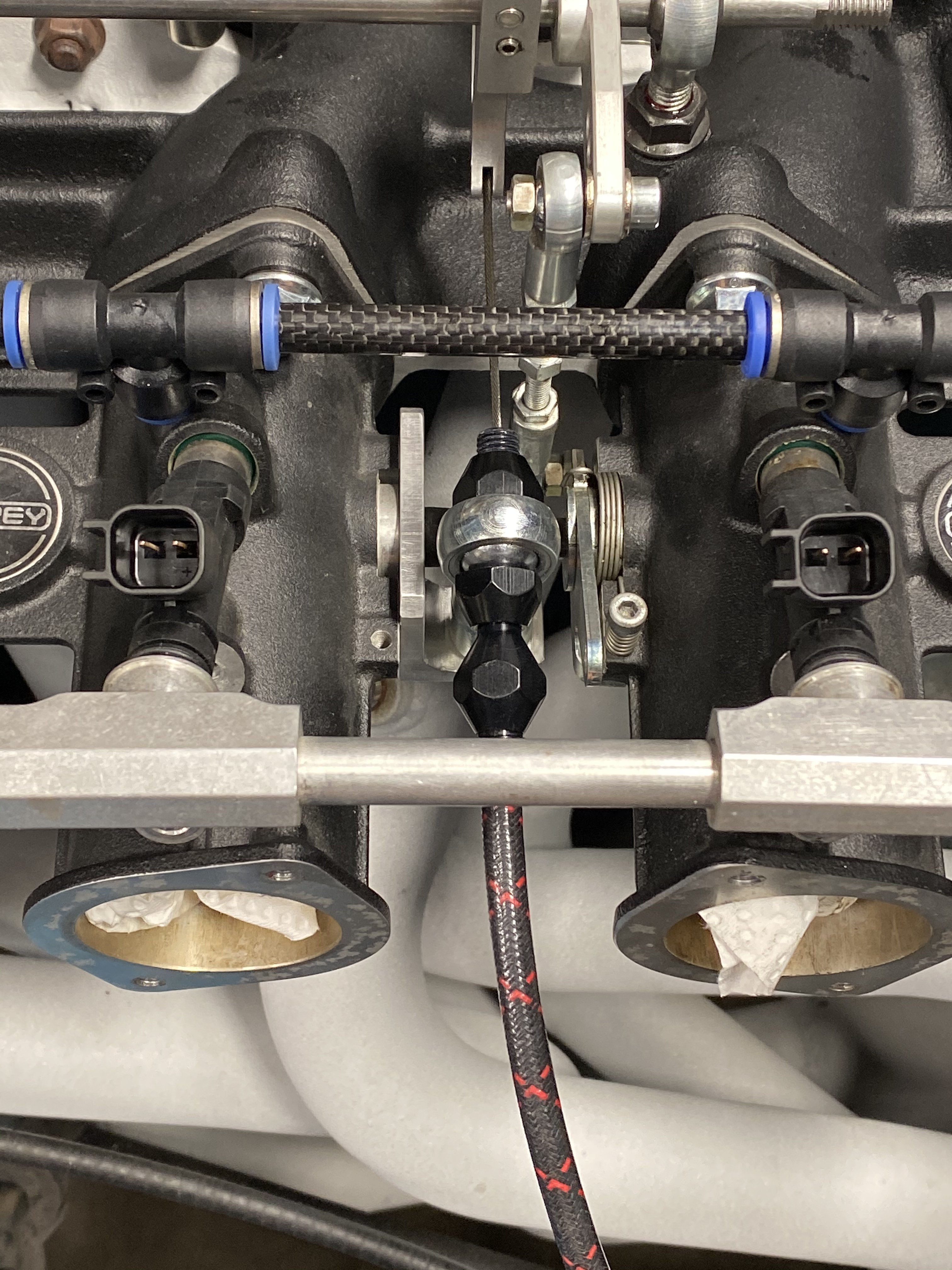
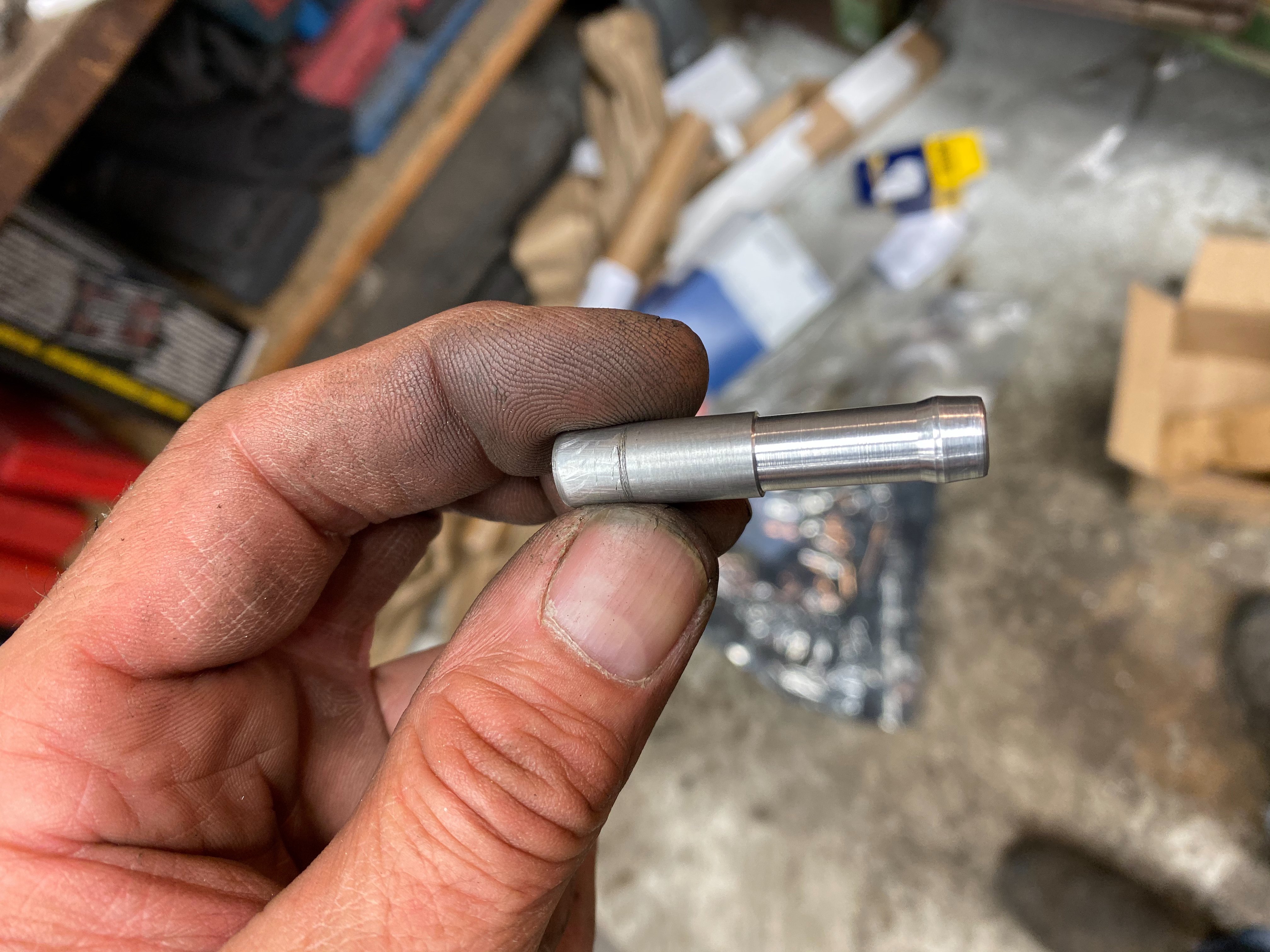
Aluminum tube. Just pushes into the tee fittings. Could be stainless, plastic, aluminum. No flare. Just cut and chamfer the end so as not to hurt the o-ring when installing. -
Fell down a Rabbit hole of mods to a good running car.
tioga replied to tioga's topic in Nissan L6 Forum
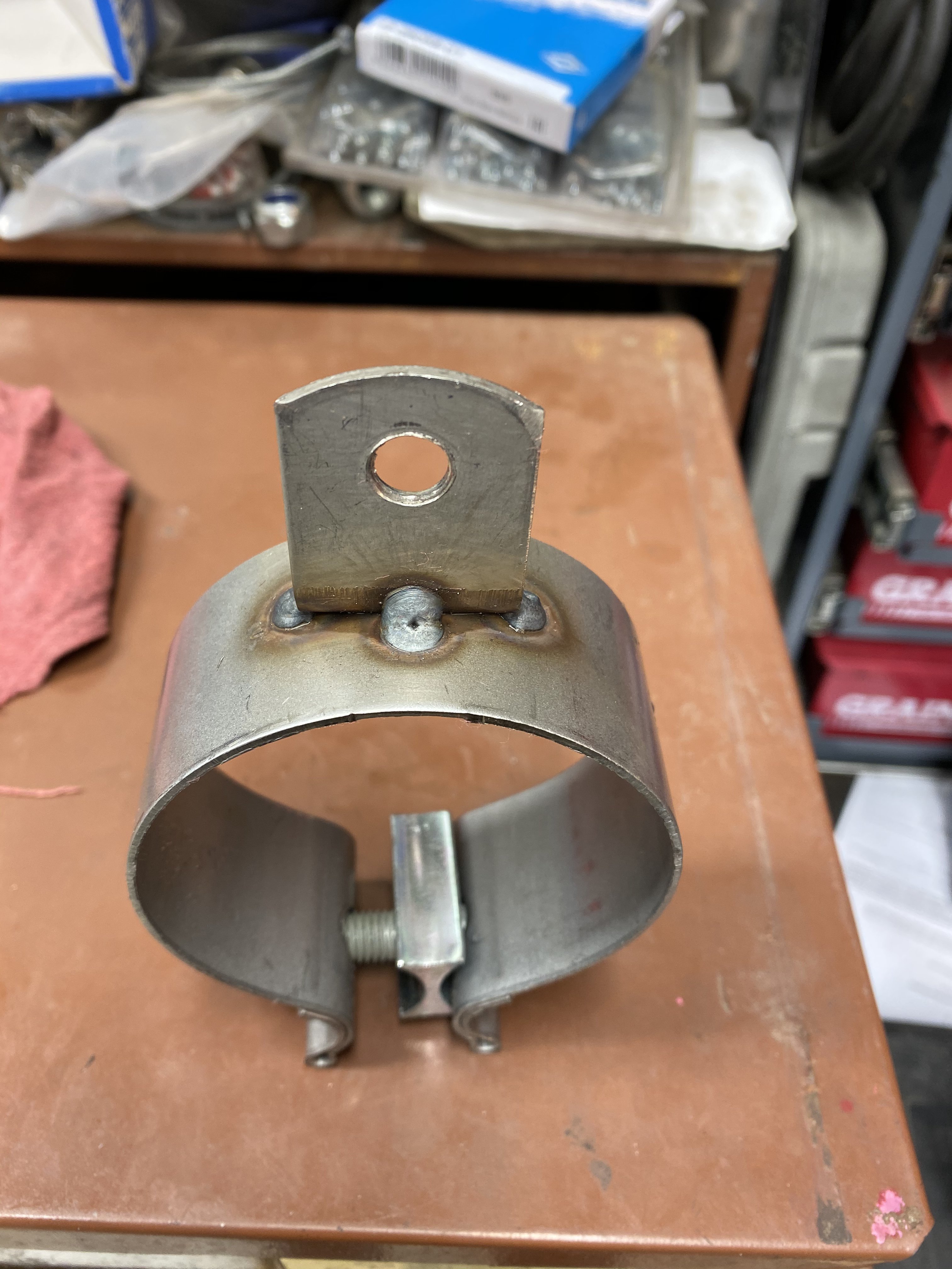
got Some exhaust done. I haven’t Tig welded in a while. Is taking me longer than I thought to get my coordination back.
-
Fell down a Rabbit hole of mods to a good running car.
tioga replied to tioga's topic in Nissan L6 Forum
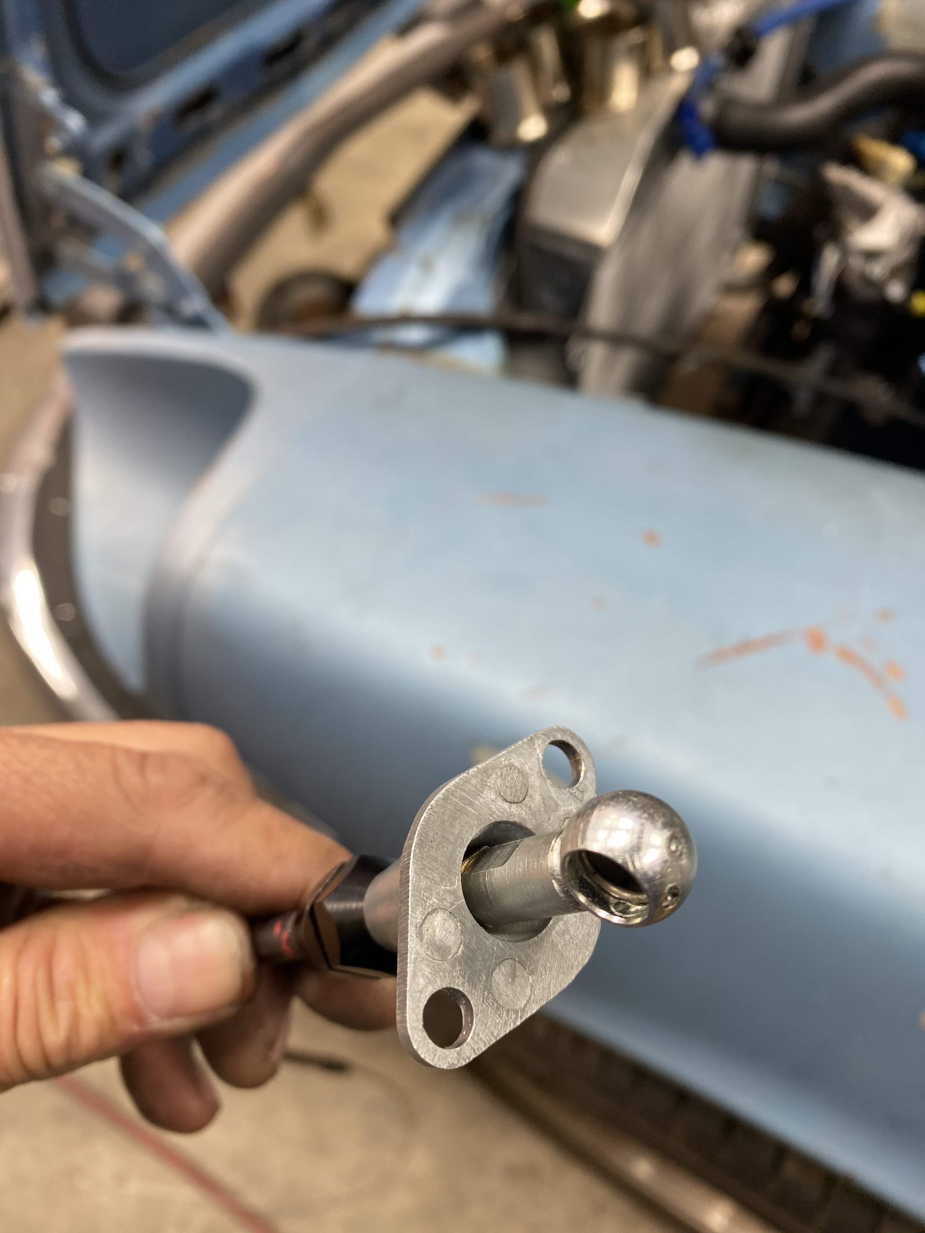
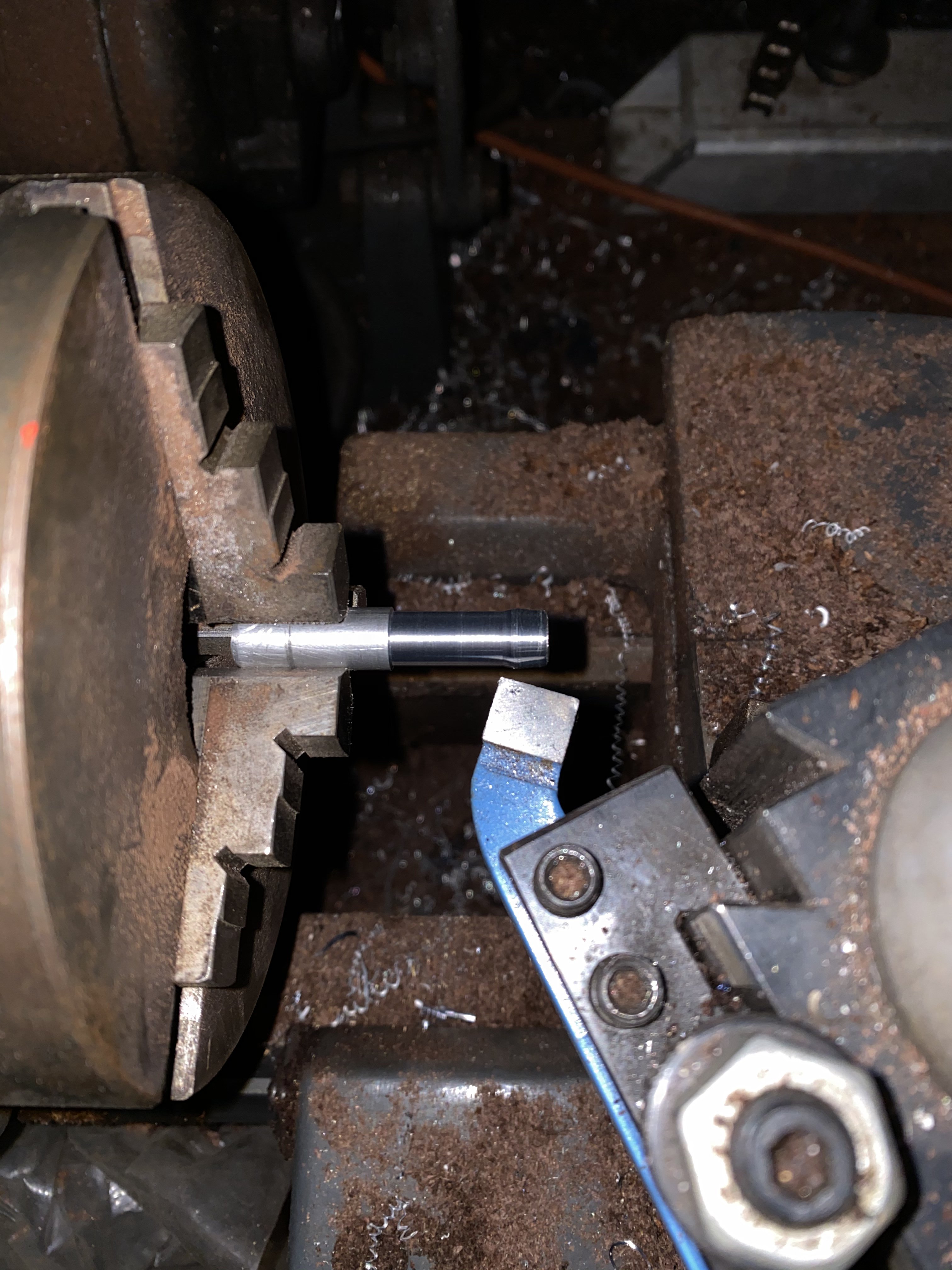
I assume you are talking to me. The push lock have stainless barbs that dig into the tubing unless you press the release. They seem to grip the aluminum fine. You can see on the pic of the nipple I made where they have made a line in the other end. If I were to use stainless tubing I would have had to make a small groove for the barbs to catch on since the tubing is so hard. I thought I might have to do that with the aluminum but they grip fine. The other nice thing about them is they swivel so you can remove them if needed with intake & exhaust in place. -
Fell down a Rabbit hole of mods to a good running car.
tioga replied to tioga's topic in Nissan L6 Forum
I will try to finish the exhaust later this weekend but I did fire it and it still runs. 0B8DA4E7-6B62-47C1-BB34-D932B87D380F.MOV
-
Fell down a Rabbit hole of mods to a good running car.
tioga replied to tioga's topic in Nissan L6 Forum
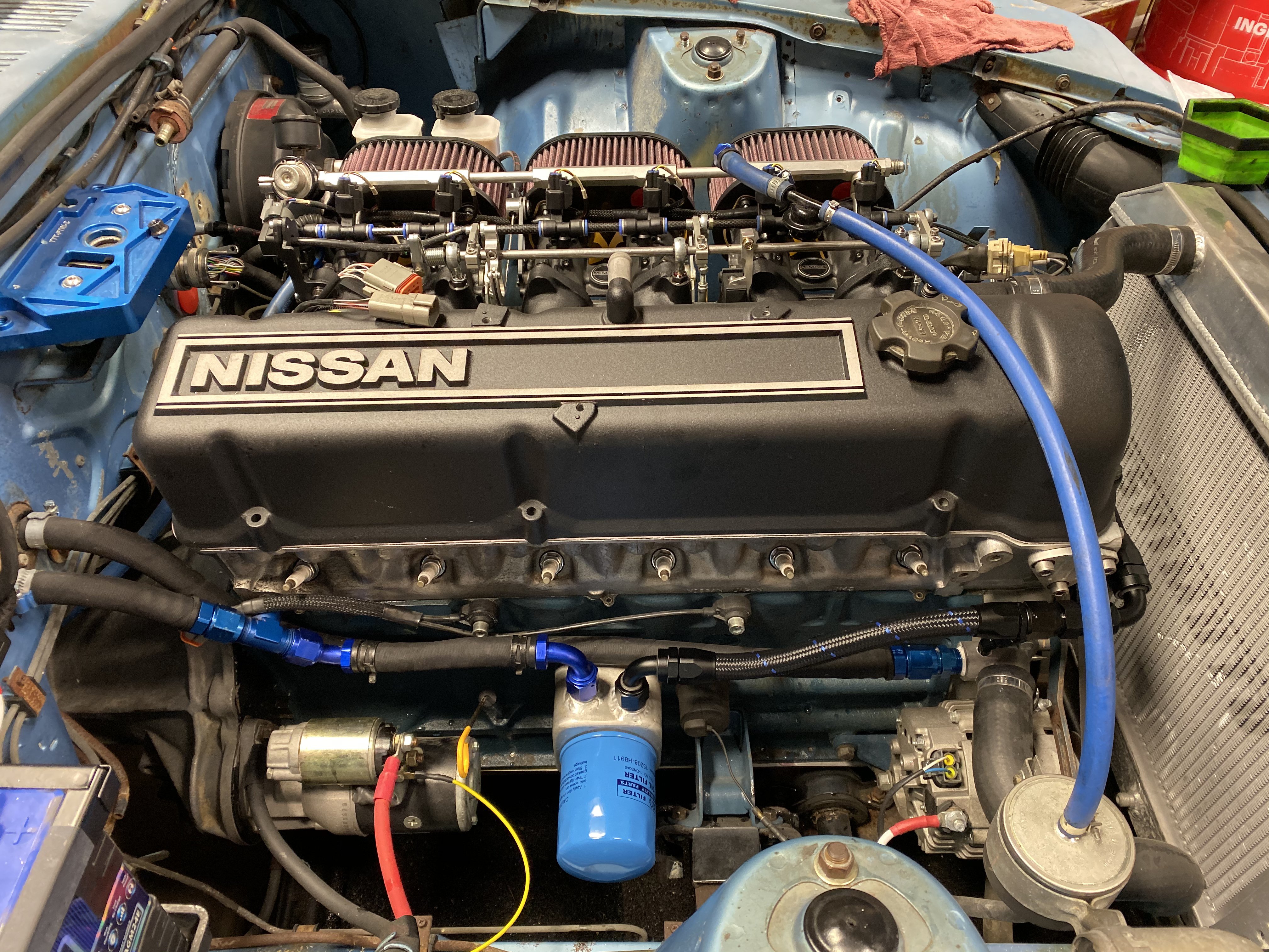
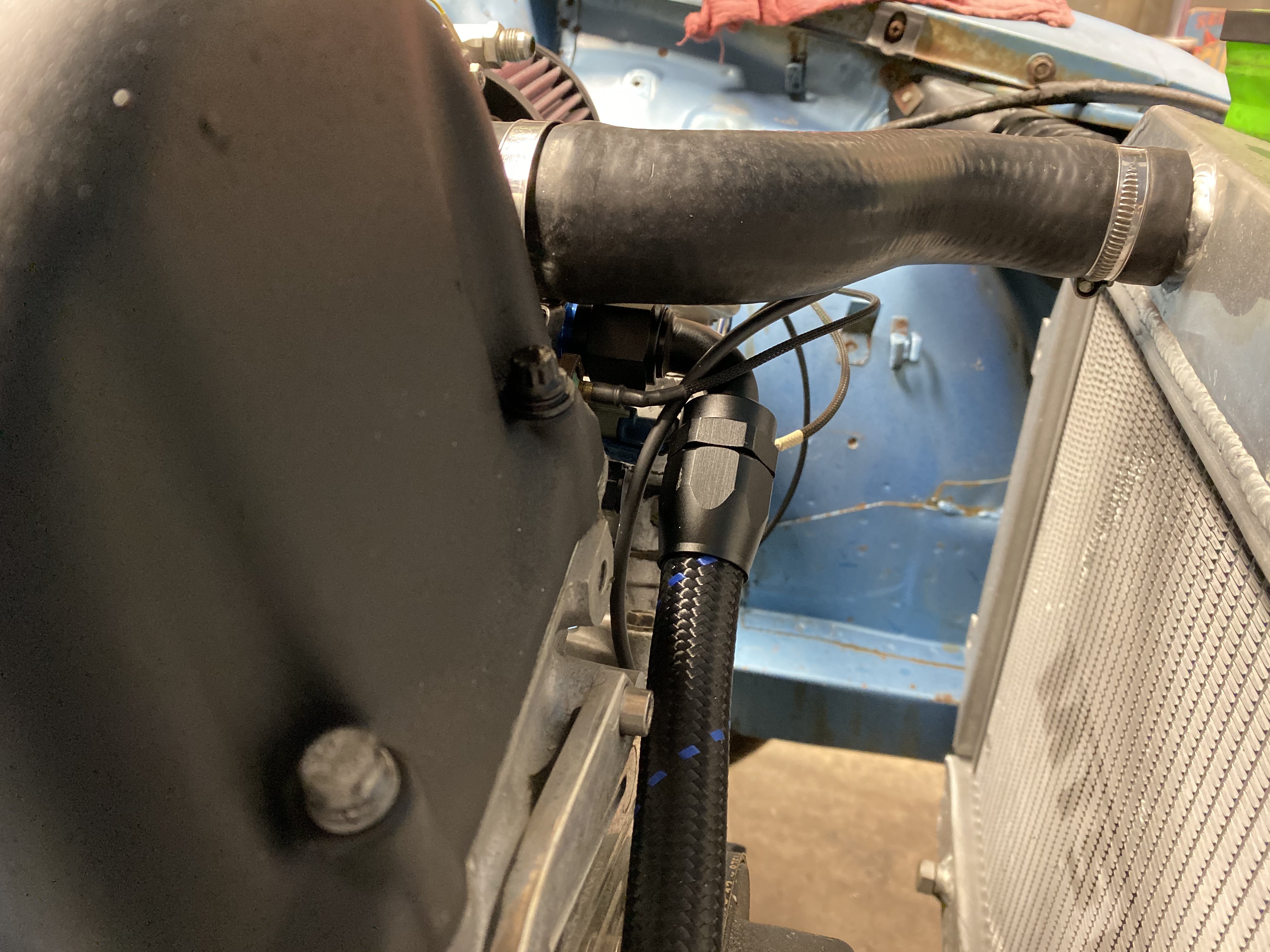
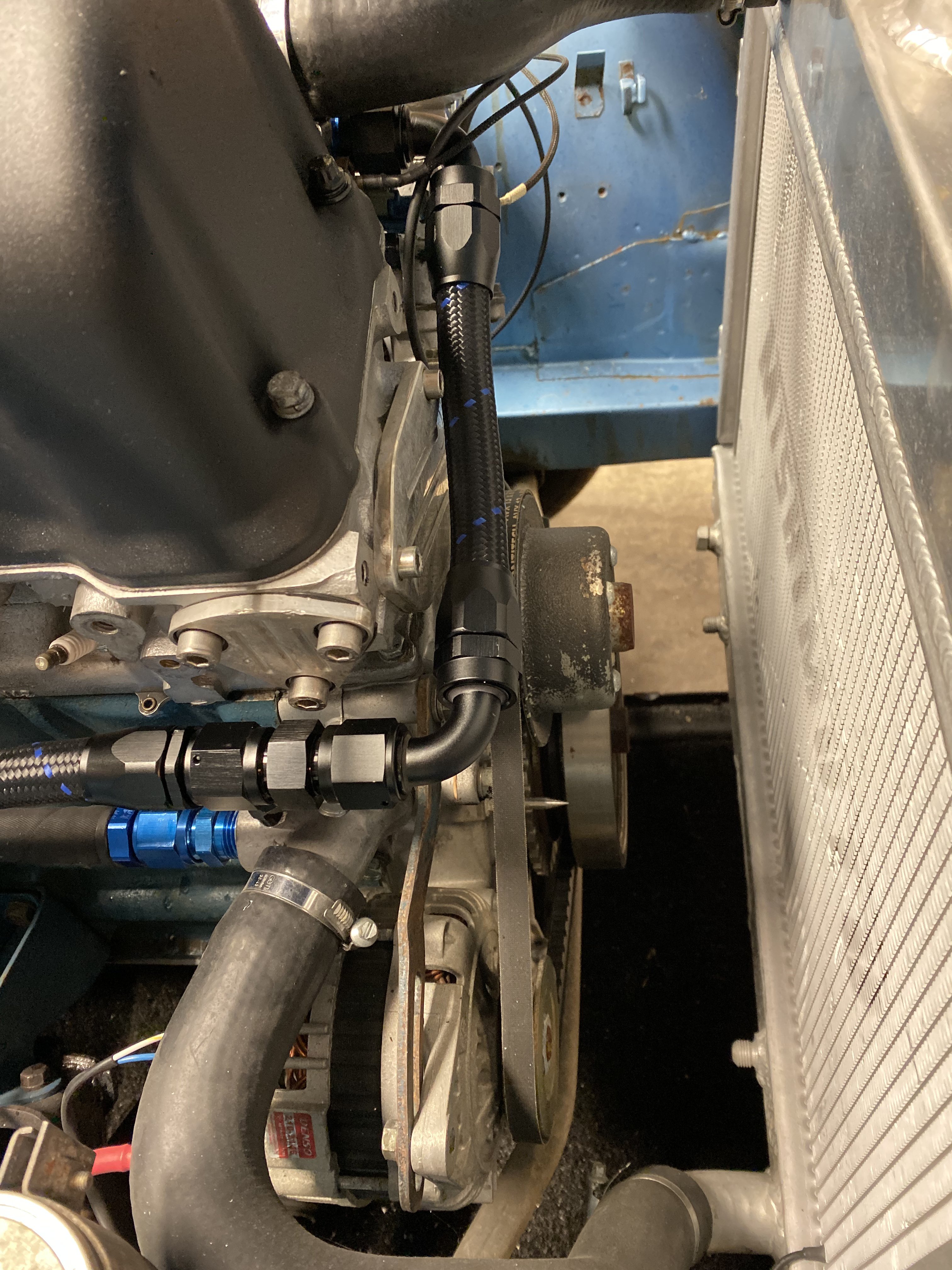
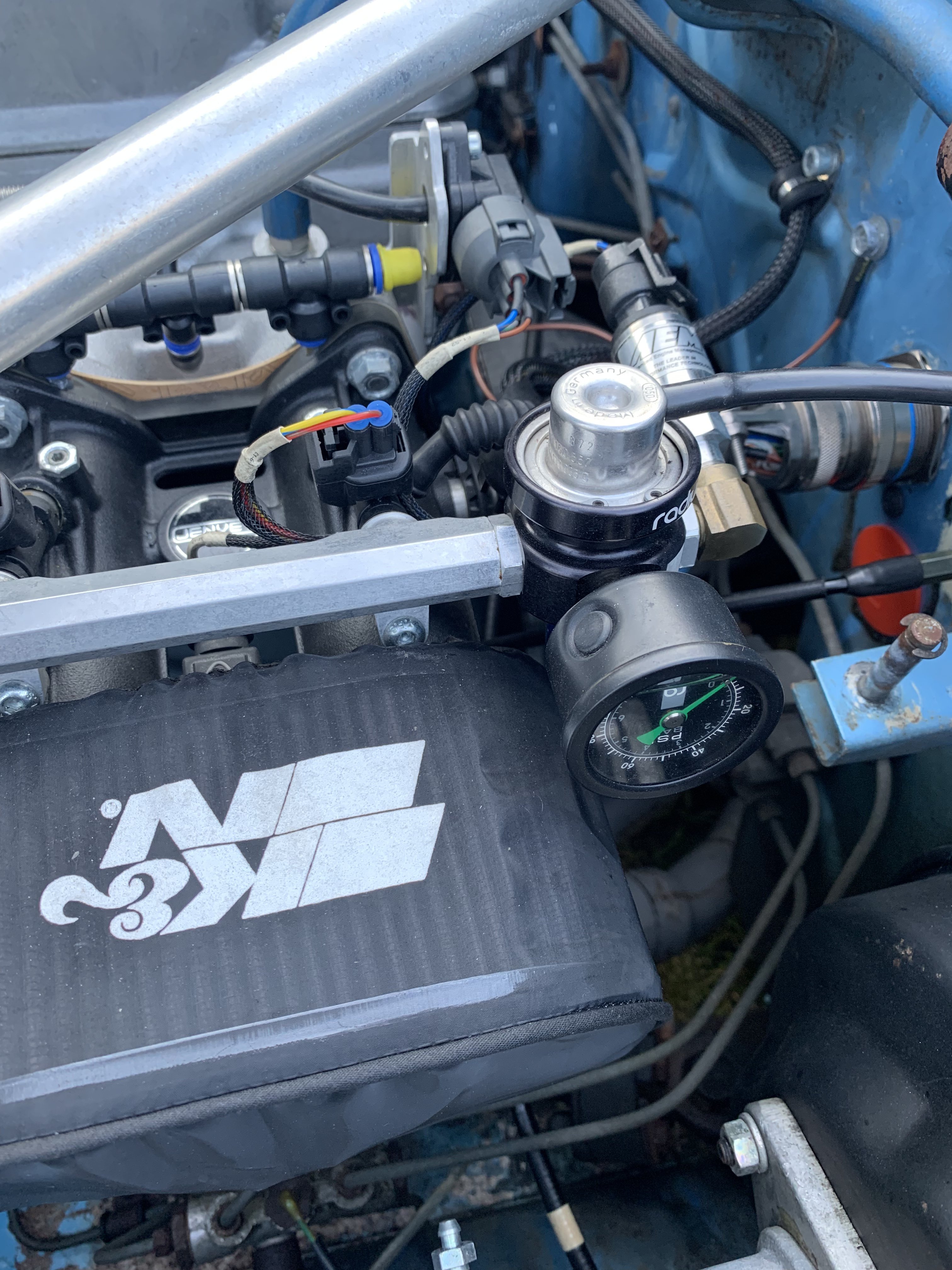
Oil cooler plumbing into the thermostat housing. It will be a tigh fit to get 10an flow into the thermostat-time sensor location. There is not much wall left but it fit. i was one short on black 90* fittings so I will have to redo the other hose later.
-
Fell down a Rabbit hole of mods to a good running car.
tioga replied to tioga's topic in Nissan L6 Forum
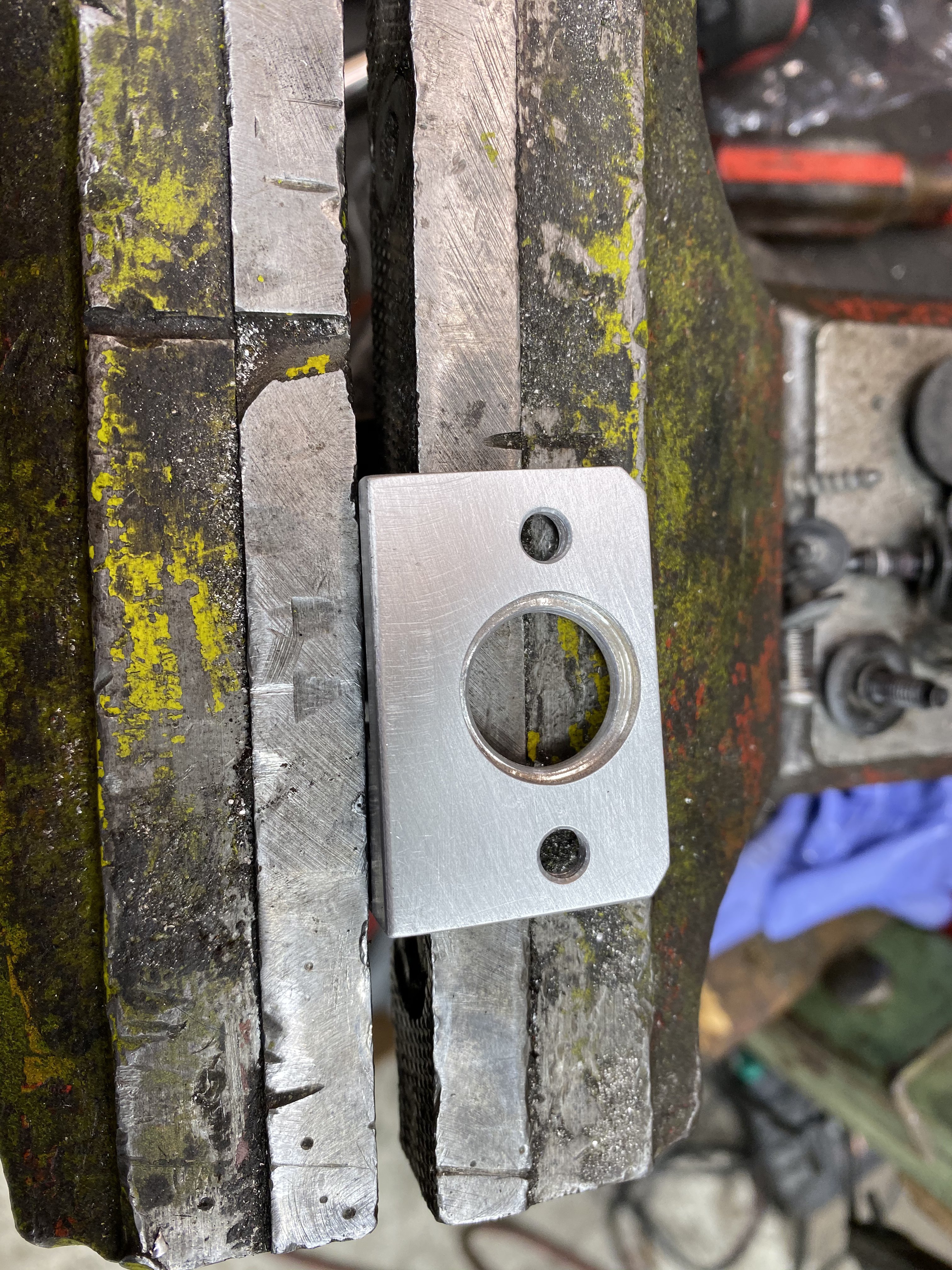
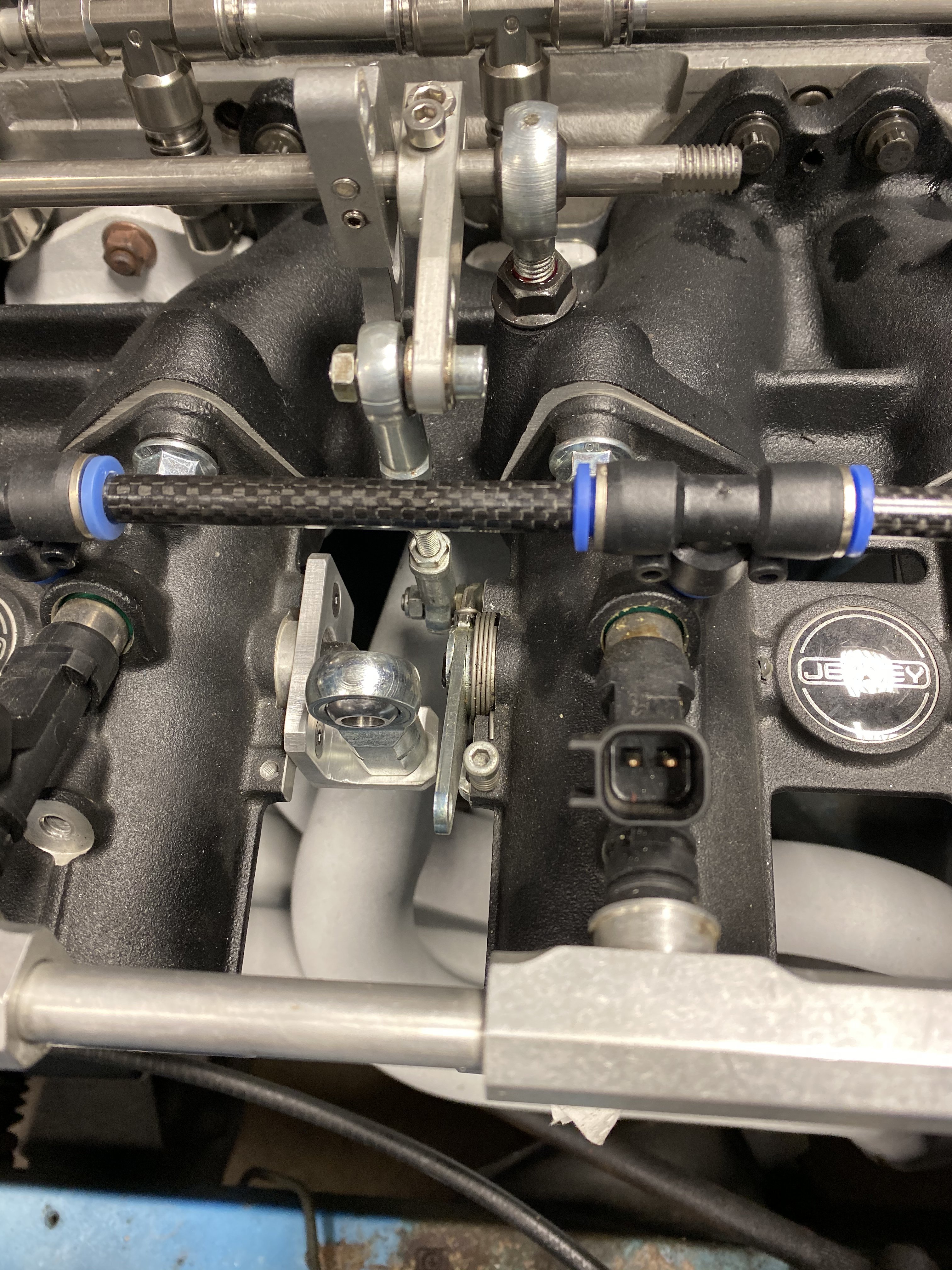
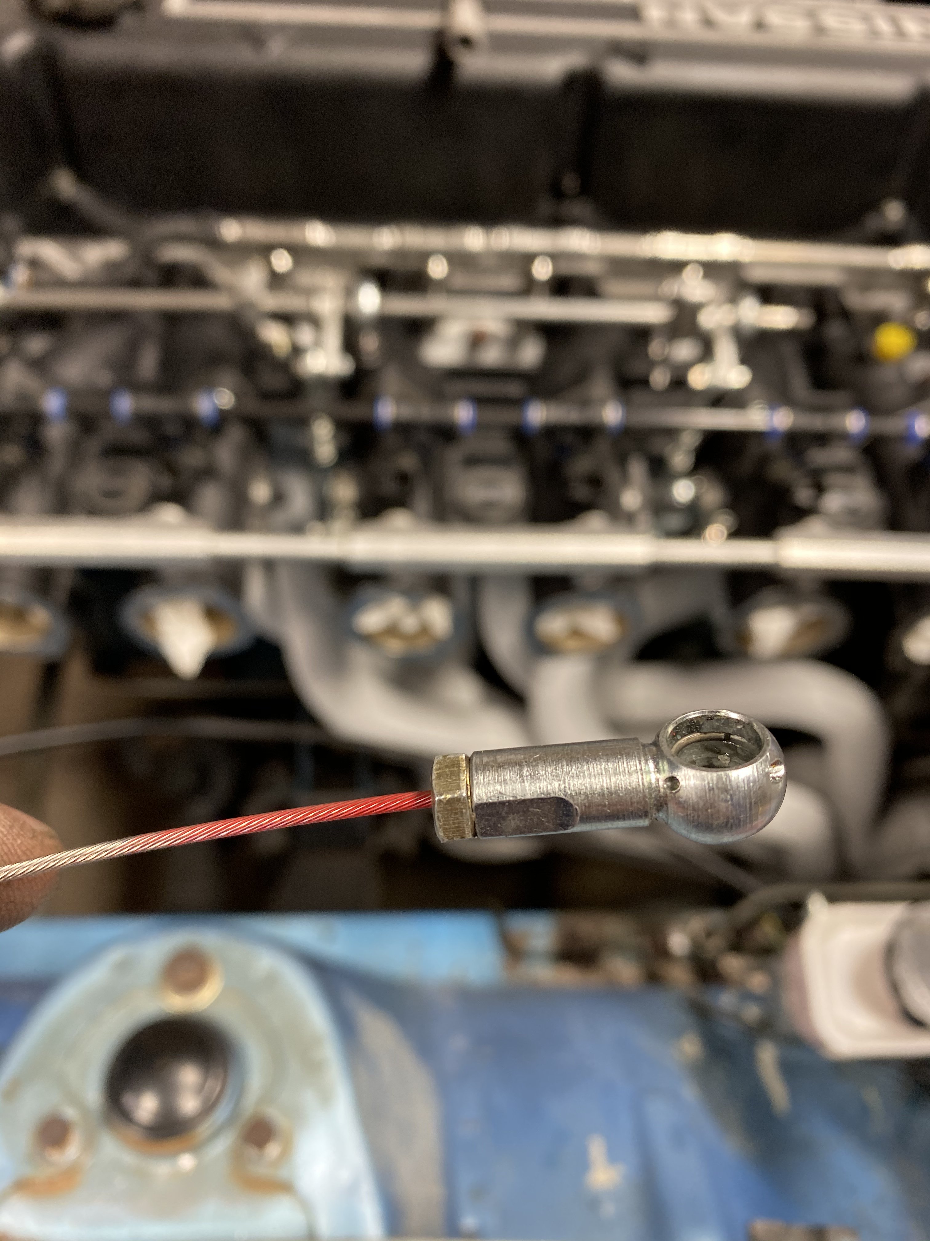
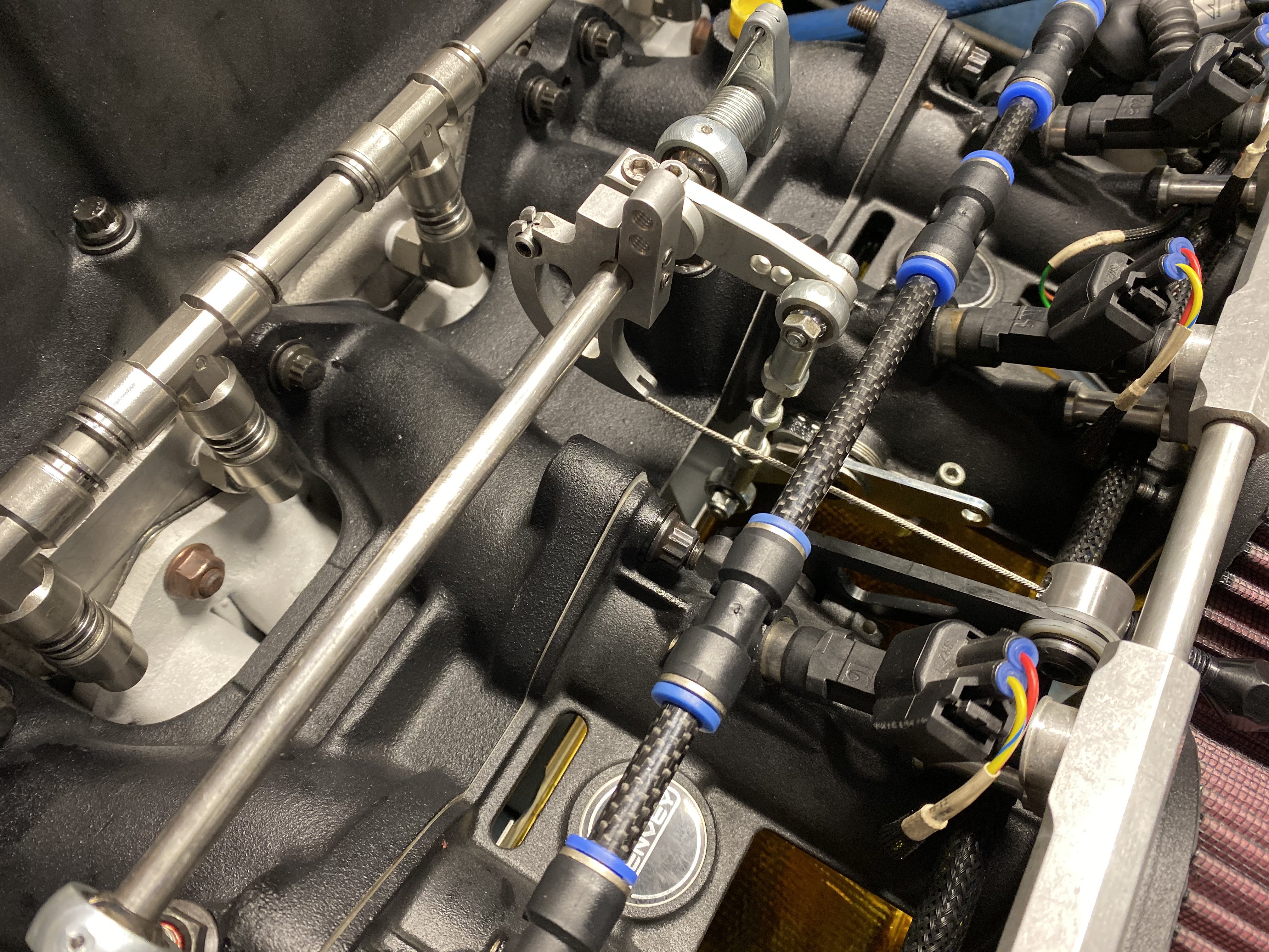
V1 of throttle cable was going to use a rod end for a housing mount at the throttle body. while this worked it was crowded and not quite what I was looking for. While I think about another solution I turn to the firewall connection and try to improve on what I had used before. I wanted a stand-off so I could use a full length socket connector on the end of the cable instead of a cut down one. After combing the net for pics of possibilities I ordered what I thought would work. Not only did it work great but the holes were exactly the same spacing as the plate I had previously bolted to the firewall. Seemed meant to be. after more searching I found a cable bracket that would attach to the throttle position sensor holes only problem was the cable mount was too offset from the bracket so I had to machine a new one to mount the cable as close to the bracket as possible. Throttle cable finished. Next plumbing.
-
Fell down a Rabbit hole of mods to a good running car.
tioga replied to tioga's topic in Nissan L6 Forum
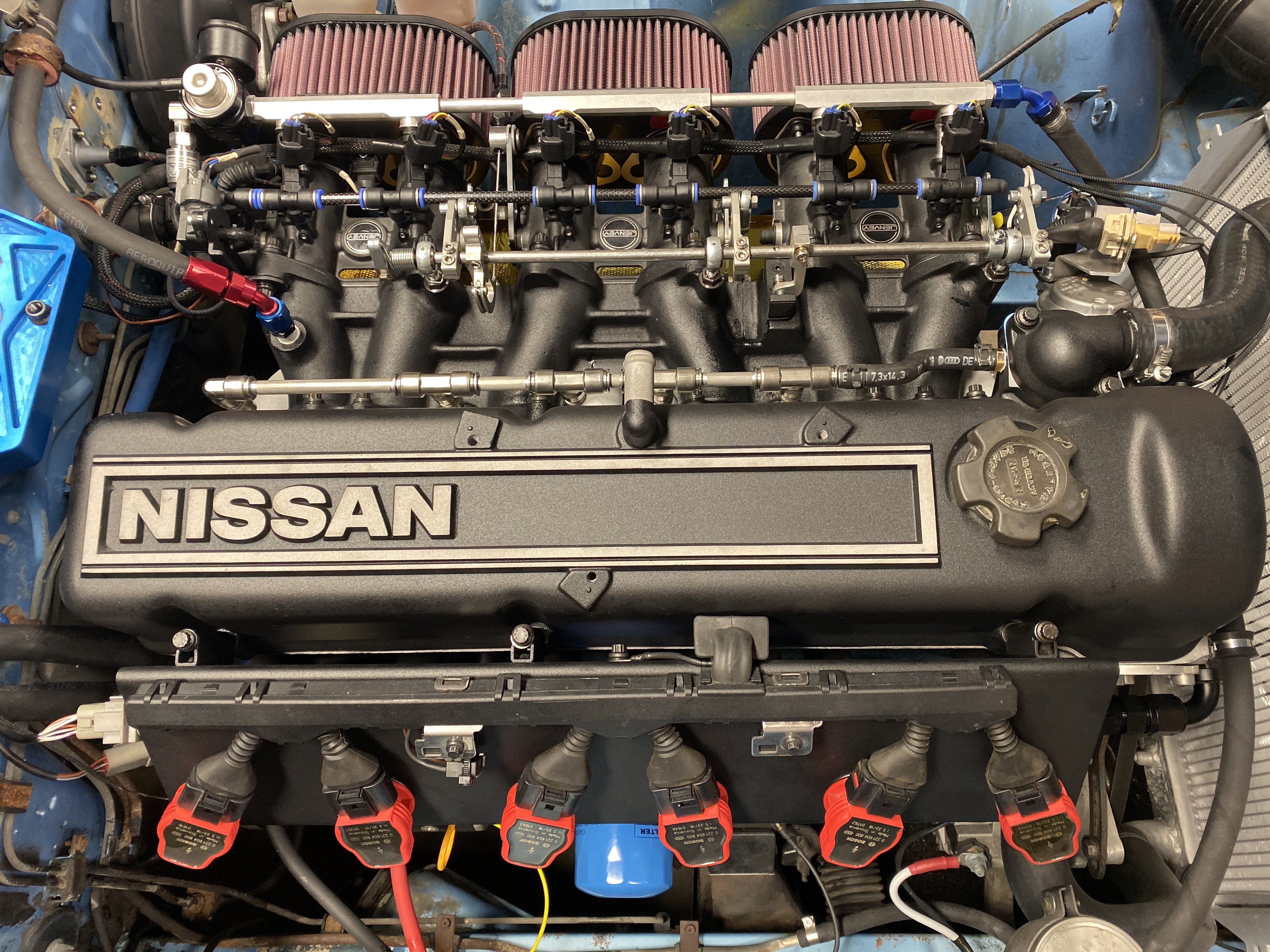
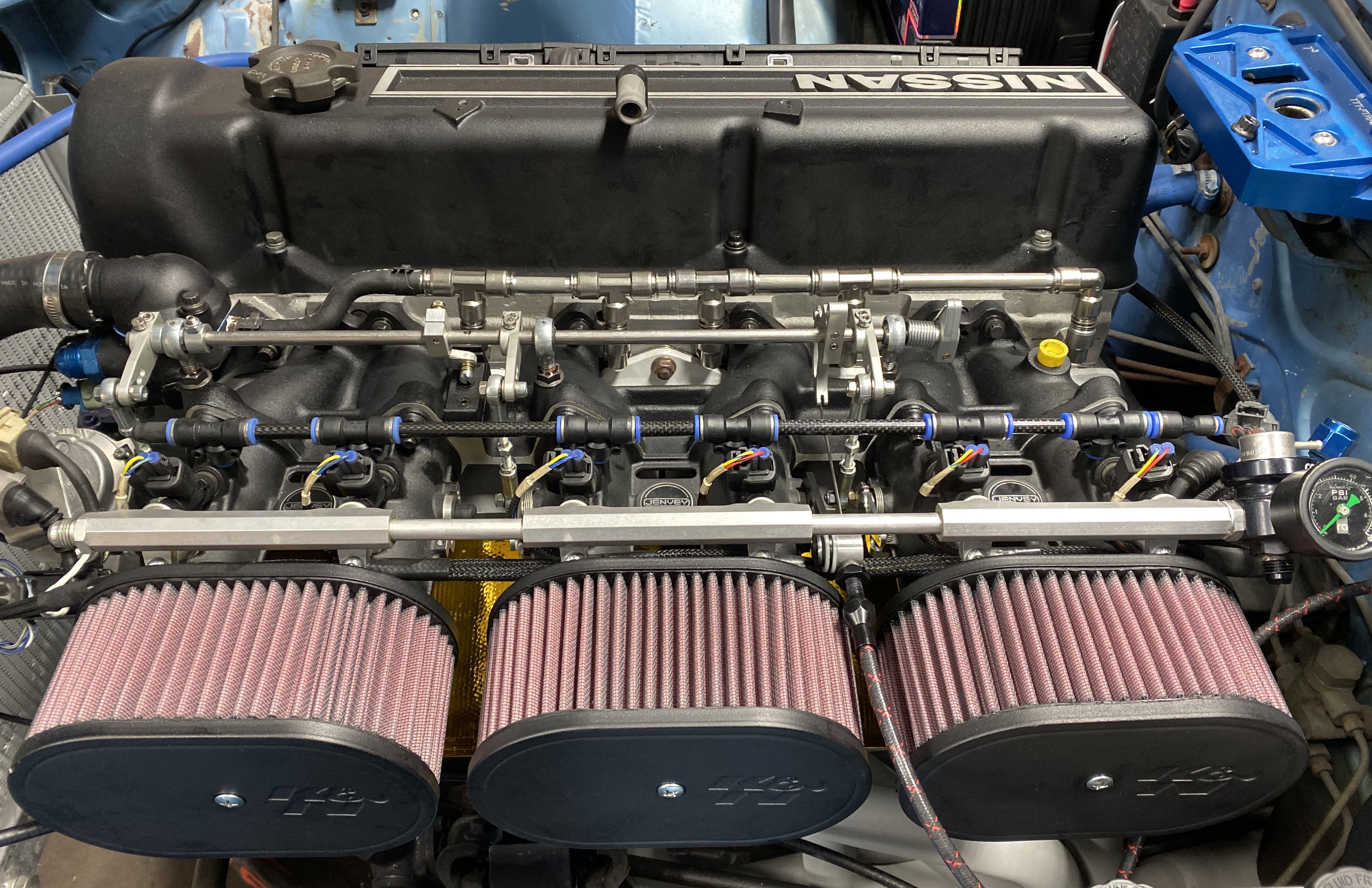
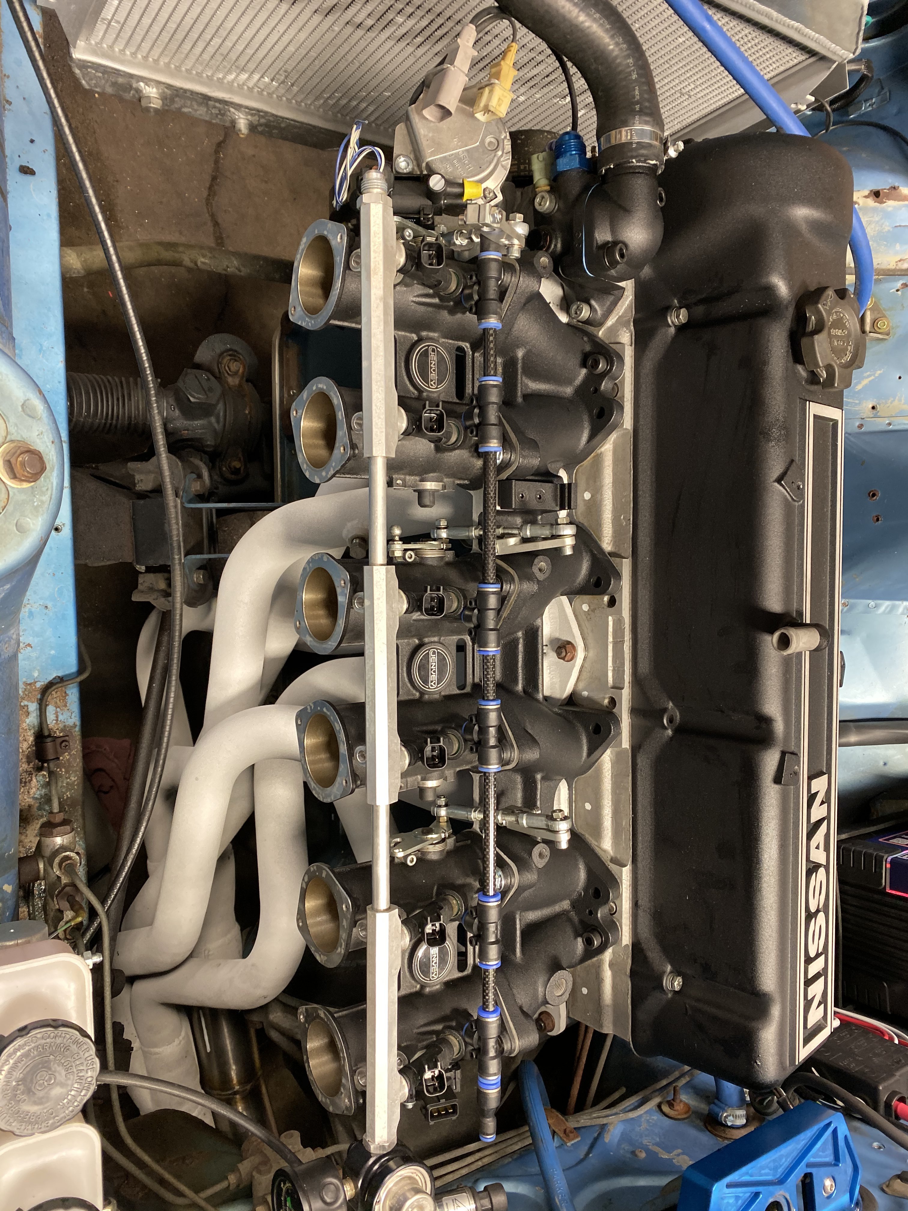
Test fit the intake take after installing the push lock fittings. turn a nipple for the end fitting hose connection All connected and plumbed into the thermostat housing next comes the throttle cable
-
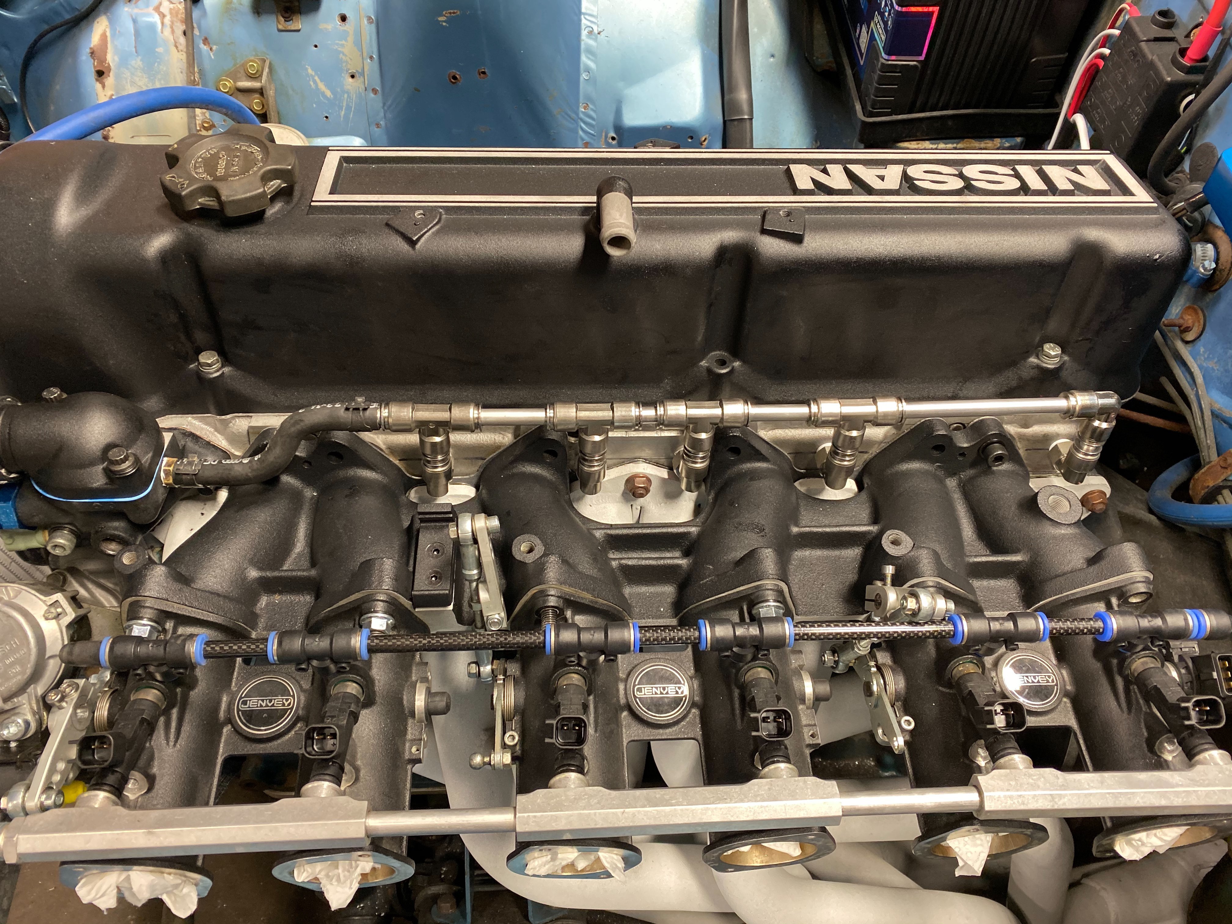
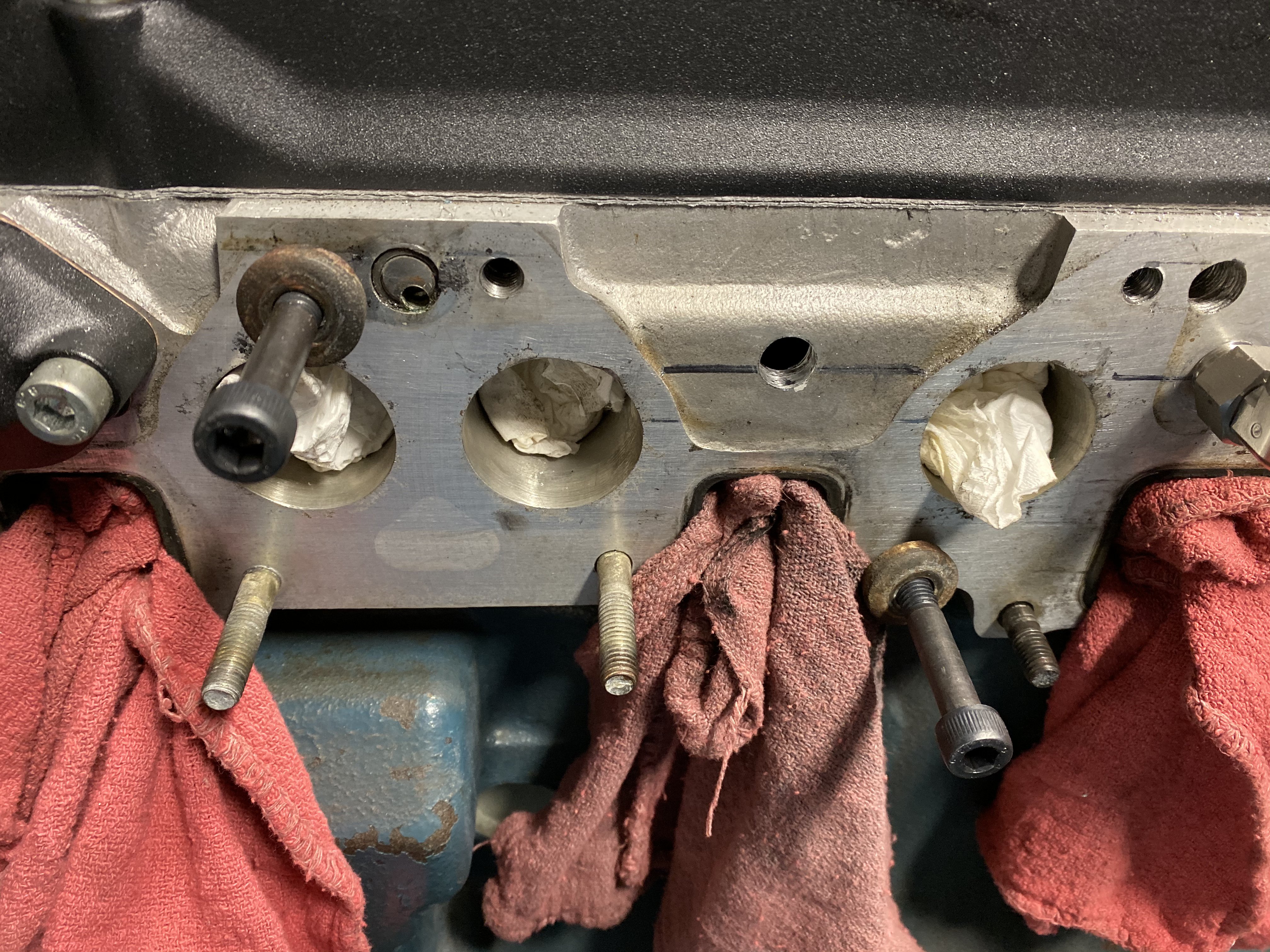
It all started innocently enough. I thought I would powder coat a few valve covers I had laying around. That made me think it would look nice if the intake matched, air filters should match too, then the thermostat housing and coil bracket. While the intake was off it seemed like I really should use one of the sets of Nissan Motorsport headers I have instead of the pace setter that are on the car. Then I need to fab up a new stainless exhaust system to mate with the new headers. Next I start thinking I would like to do the cooling system mod for cylinders 3,4,5,6. I also felt like when the thermostat housing is off I would try to plumb my oil to water heat exchanger into the thermostat housing instead of the inlet of the water pump it had been plumbed into. With the new headers my under throttle body throttle cable system was all over the headers and needed to be redone. And so it continues. I used a pressure regulator to put 10 psi in the cooling system so when the head was drilled for the cooling system the cutting chips did not go inside the head. This worked great. After each hole was drilled and tapped I plugged it so I could pressurize for the next hole. The height I guessed on was perfect almost exactly flush with the roof of cooling passages. I love a push lock fitting so I ordered a few stainless high temp fittings to use.
-
It kind of does. Im not saying it’s not done or doable. Like I said Porsche did it on production cars. In that case they did give you a mechanical lever to raise idle by simply pulling on the throttle cable. This helped keep the motor running and sped up the warming process. A motor when cold requires a LOT of extra fuel to run correctly. This shows up the most at idle when it can easily stall. The accelerator pump will give it the shot of fuel it needs to ignite but after that your motor does not run/idle well. You can continue to tap the pedal to add accelerator pump fuel and help out. I am not saying it doesn’t work or that I haven’t done it but there are better ways to start a engine. When you have a cold enrichment devise already installed why not take advantage of it. A motor set up with the correct 12.5-14.7 ratio usually on one of these old L6’s they idle pretty well warm with a high 13’s to low 14’s idle mixture. This same mixture will not work nearly as well on a cold motor. Especially if you live where temps in winter can be near zero.
-
What’s your point? Because you had a rich enough mixture to produce a satisfactory cold start doesn’t mean it was the correct way to do it. All the old Porsche carbureted cars have no cold enrichment device. When set up with a ideal idle mixture while hot it is hard to start when cold so you compromise the warm mixture to help you start it. This is a customer car with carbs that came with a cold enrichment device that I chose to have operational for the customer and was demonstrating the way I did it for other people who want to run it on theirs.
-
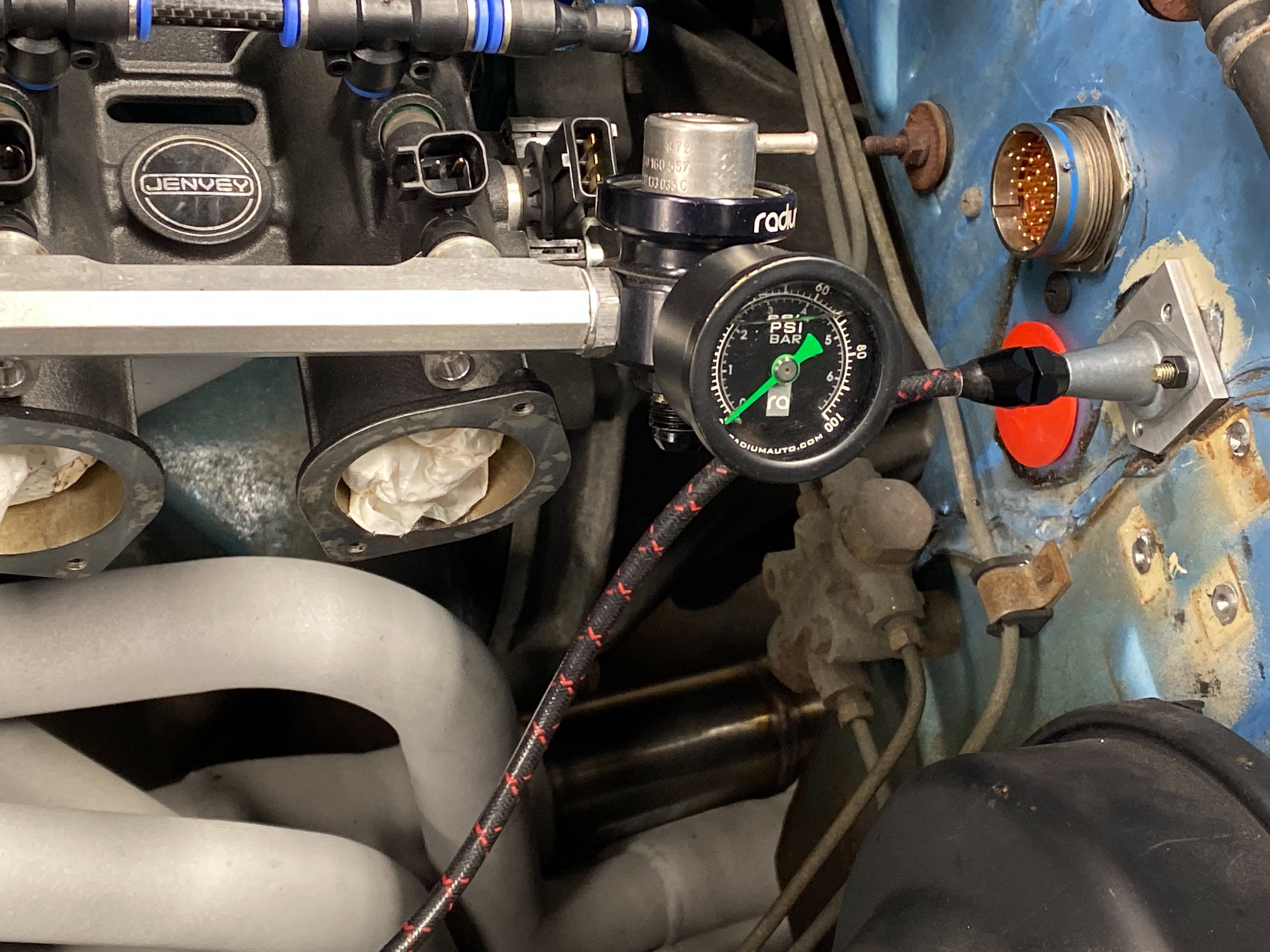
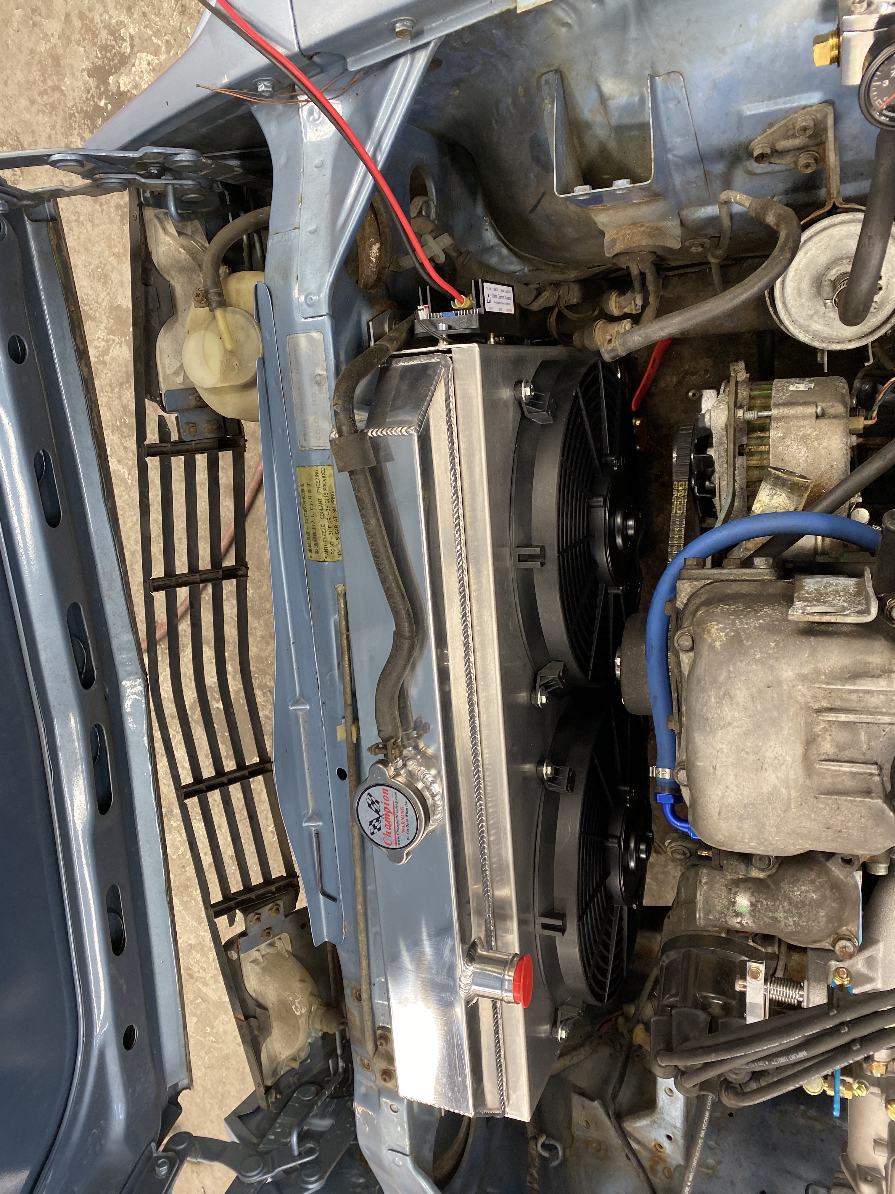
That is exactly what I have done with the Radium as well. It is very nice stuff. I got my intake and other parts back from the powder coater. I really like how it ties everything together. This has caused a snowball effect. Since the intake was off it seemed like I should put on one of the Nissan Motorsport headers I had swain tech coated. This means a entirely new exhaust, while I’m at it I want to change out my hoses and plumb my oil cooler water in under the thermostat. I am also thinking about doing the cooling system mod for cylinders 2-6. This motor was originally built as a road race motor and just had the compression dropped for pump gas with a thicker head gasket. Now that my tune is / was dialed in before the new exhaust and with the better cooling I can bump up the compression a little. I am running dual knock sensors and if I get a good knock floor with compression where it is and some race fuel I can feel good that the ecu will protect the motor with the higher compression.
-
Thanks. So simple and hidden at the same time. I always looked at a cable as the wire that does the work but that is not the case. Both housing and cable do the work together. The brake cable boot boot worked perfect too,
-
That is pretty tiny. My early 260 is 5/16
-
I would make sure there is not another cause. I am running 3/8 supply and stock 5/16 return and steady 42 psi. I have done this same set up several times. I suspect there is a restriction somewhere or you have a 5 bar regulator. I really think something else is going on.
-
Why not just buy the Arizona pan. Exact same pan as kameari for half the cost. Large capacity and trapped door baffled.
-
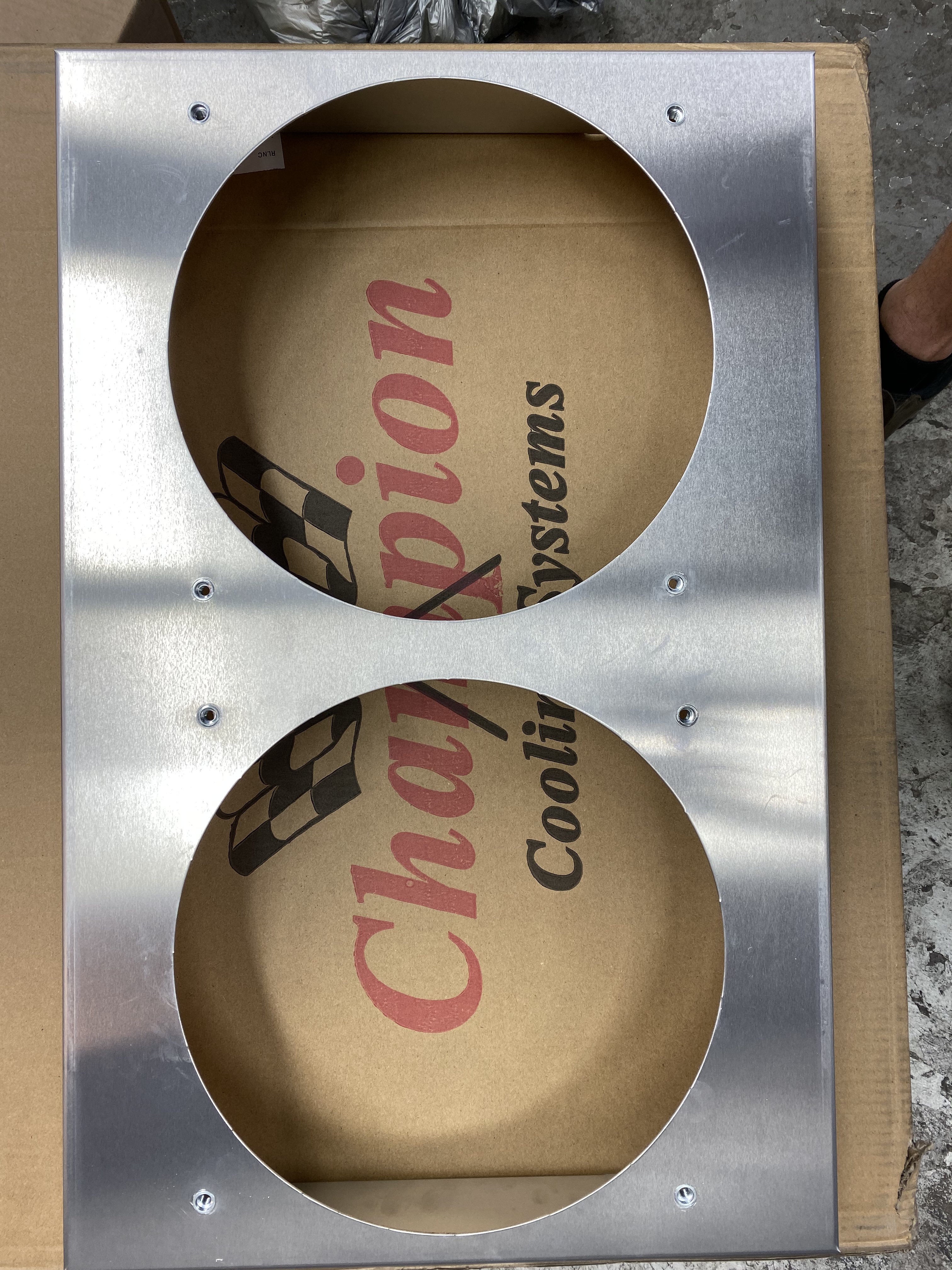
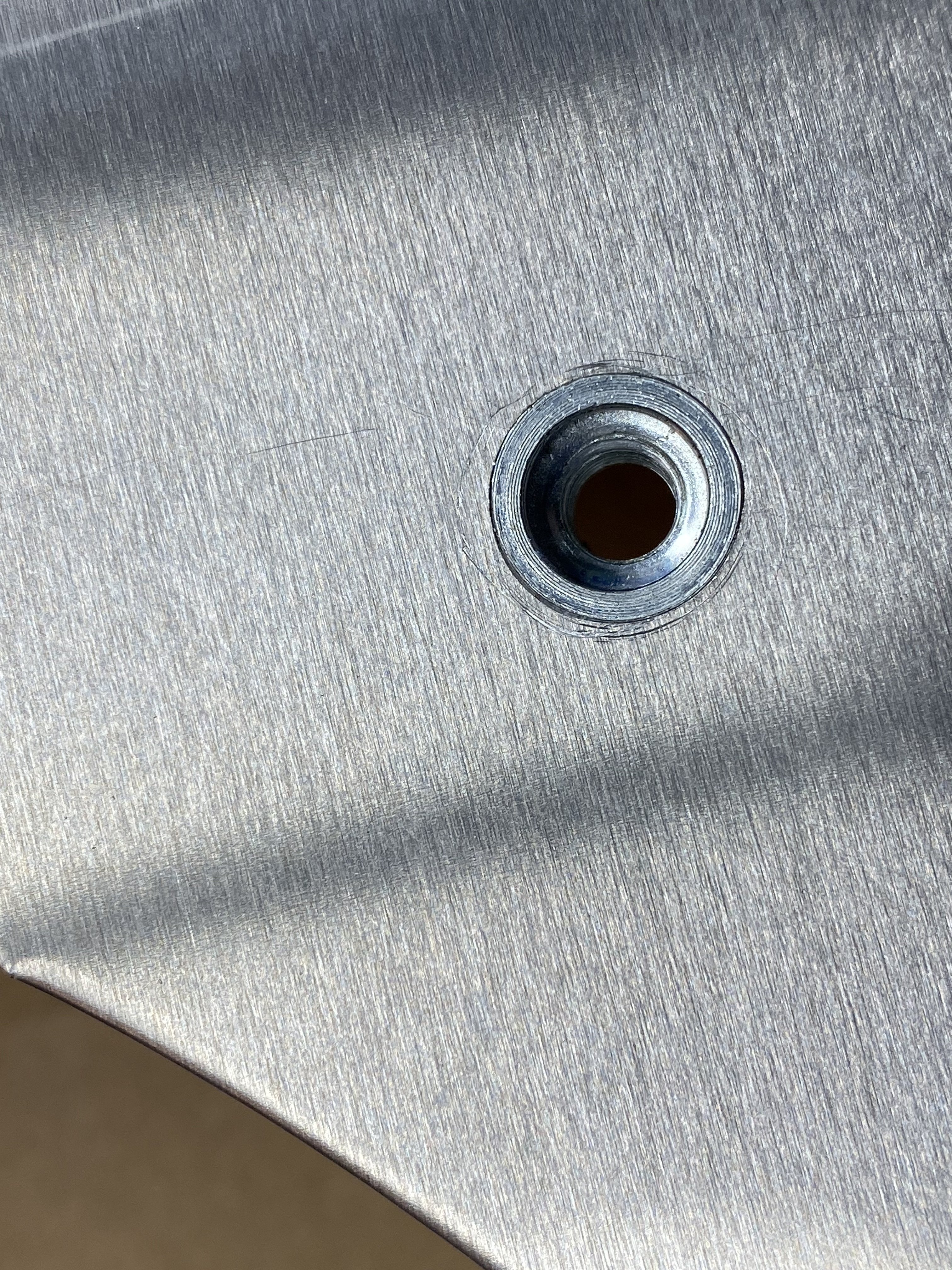
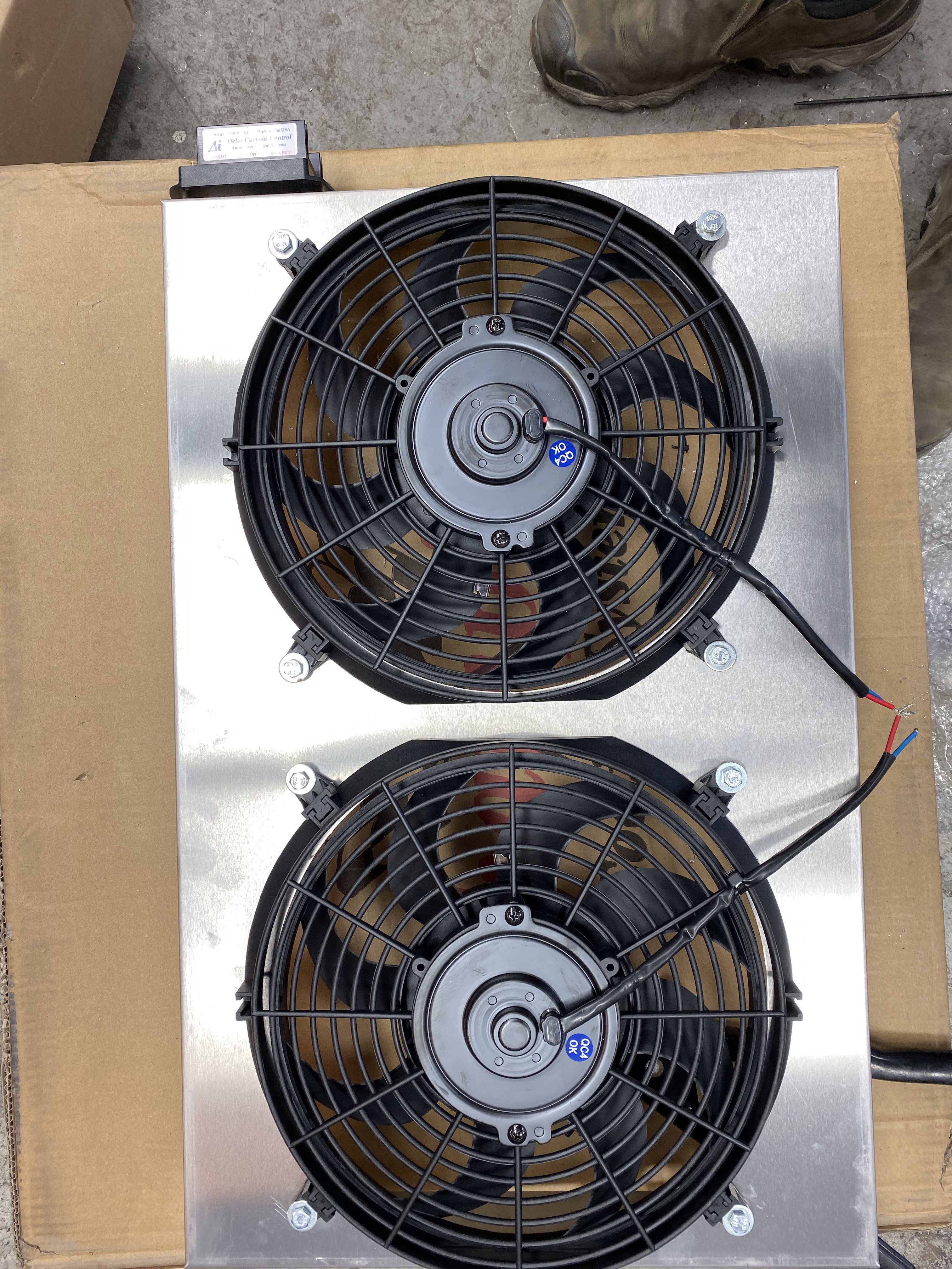
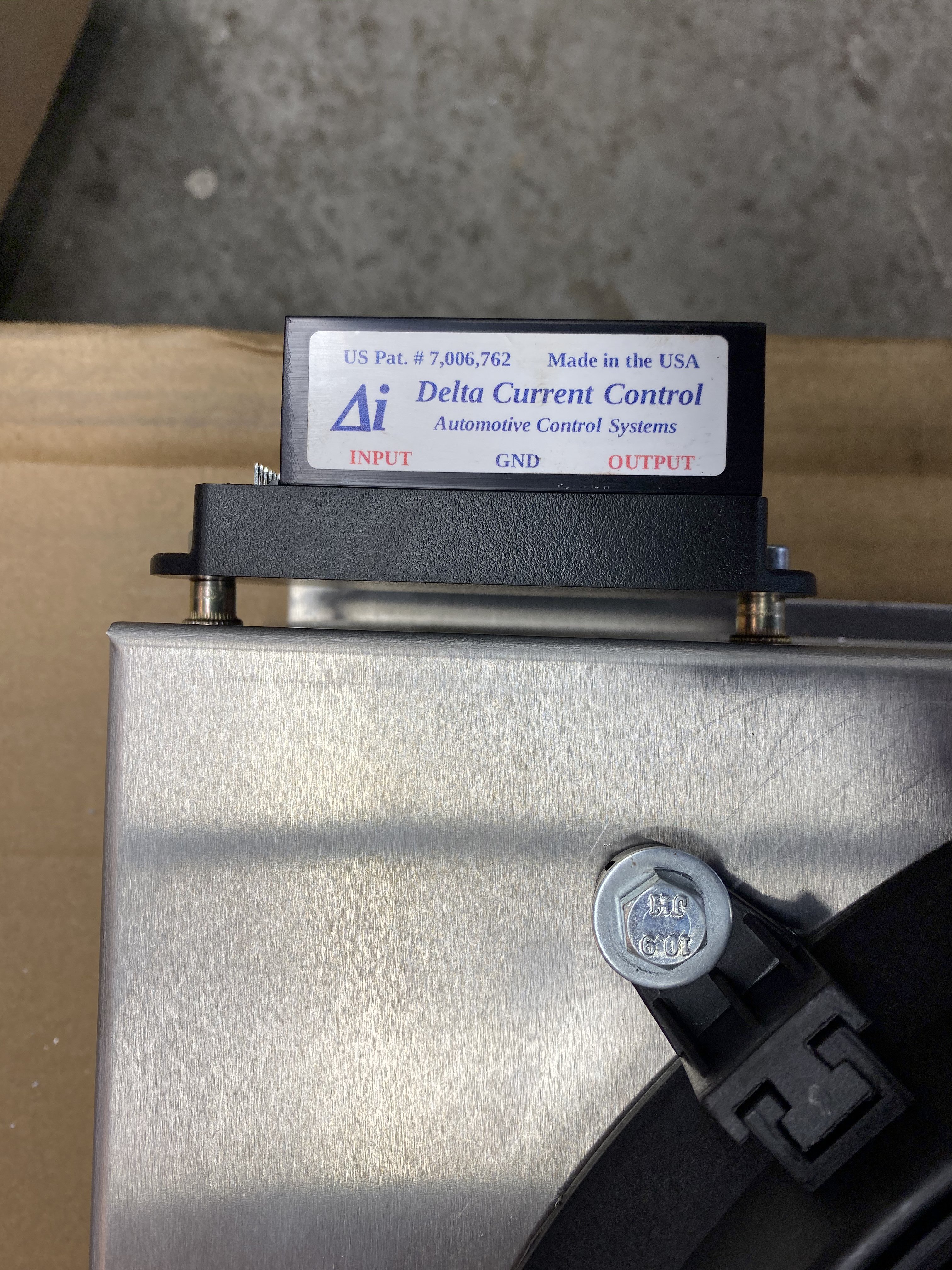
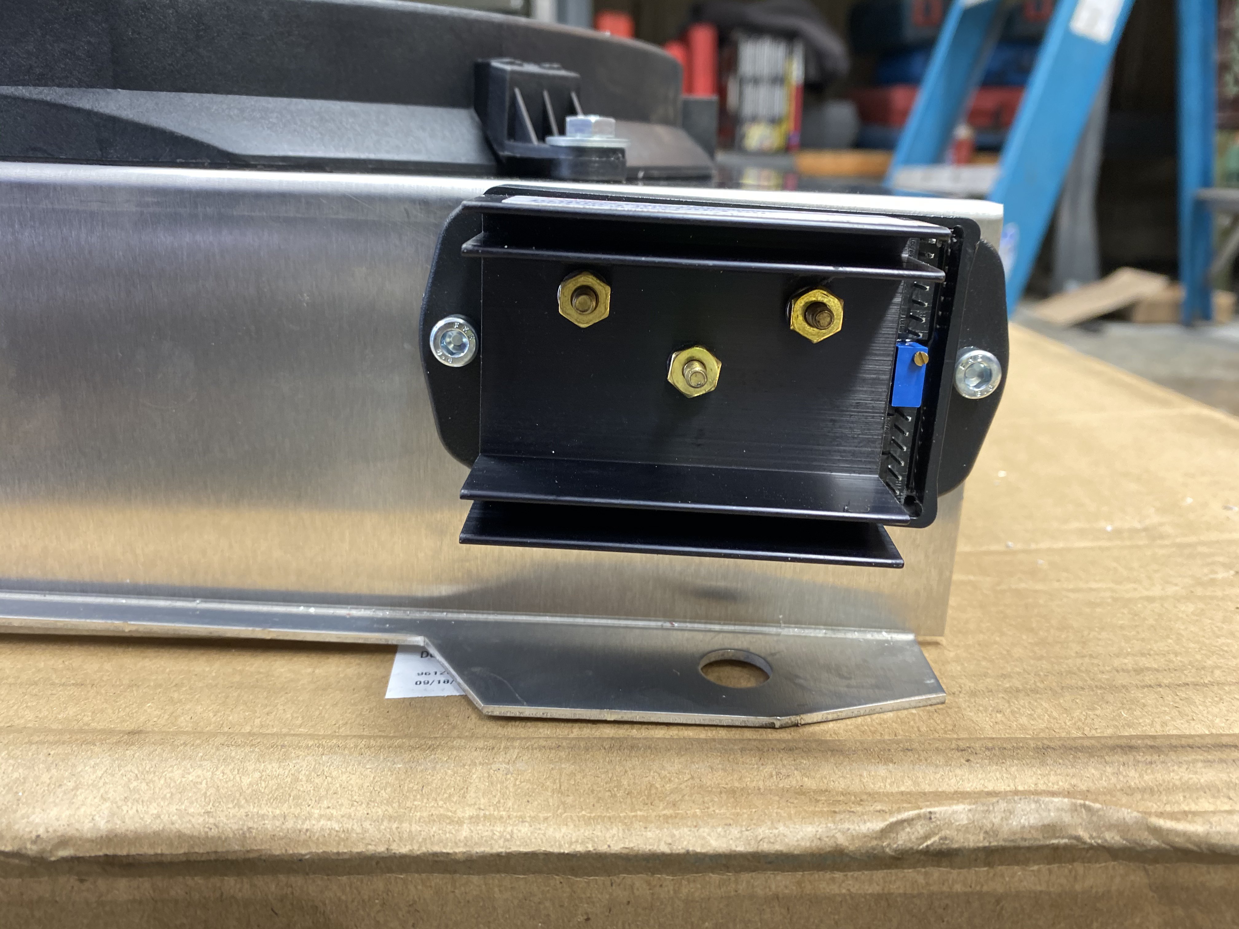
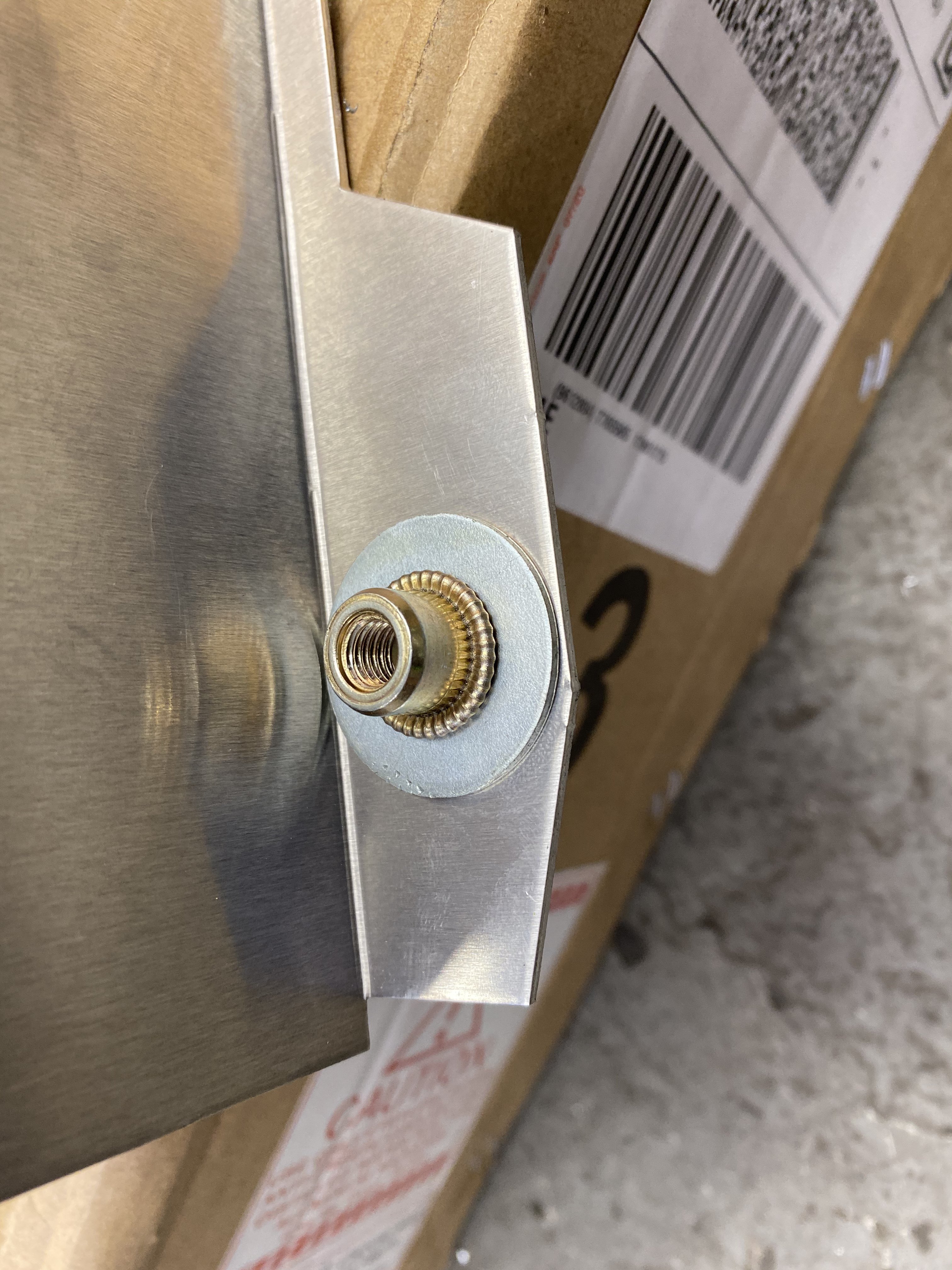
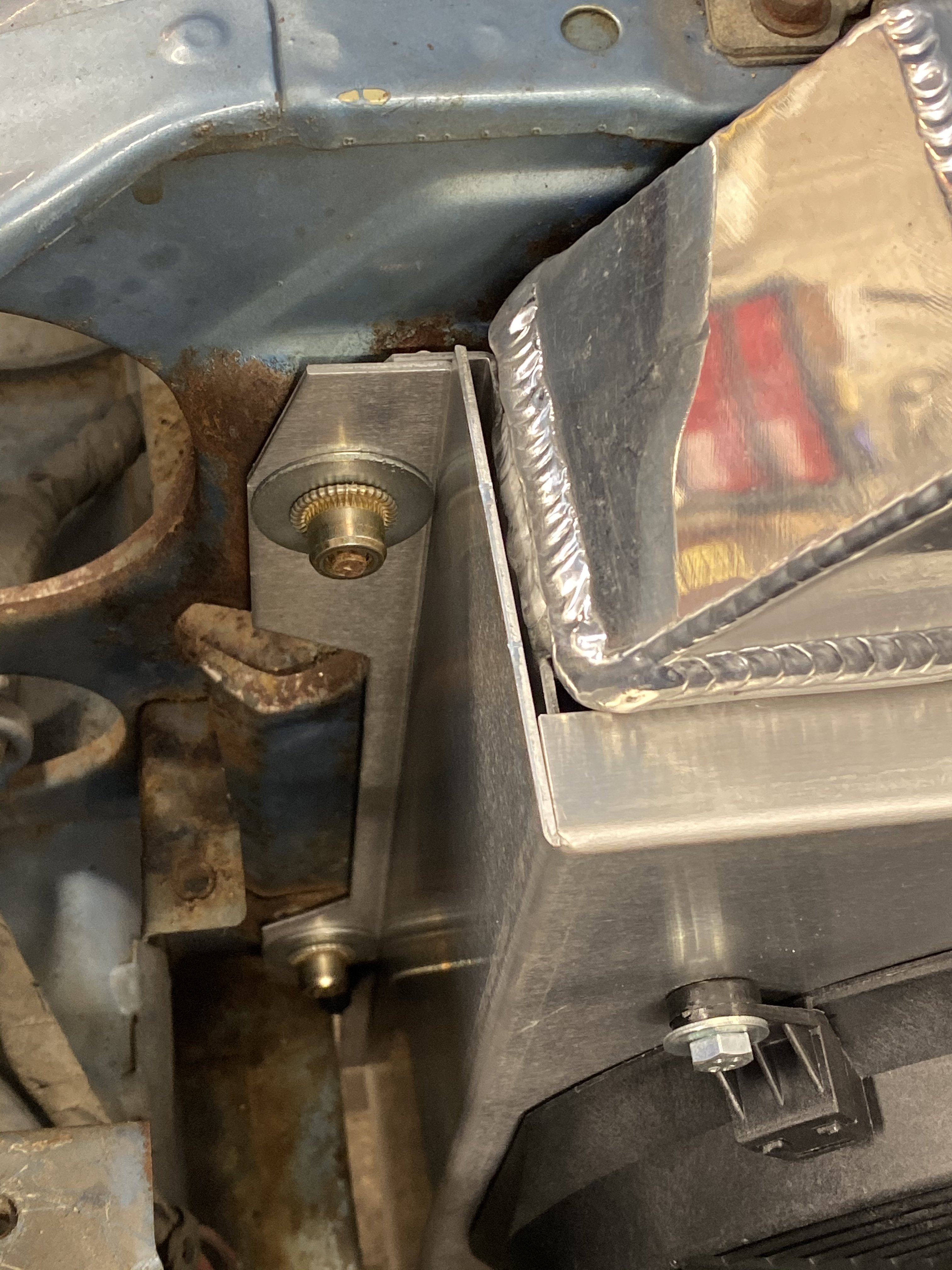
I am also a lover of nut-serts and used them on the radiator fan shroud so it can be bolted in like stock. The fans also are bolted on with nut-serts. And again used them backwards to stand off the fan speed controller.
-
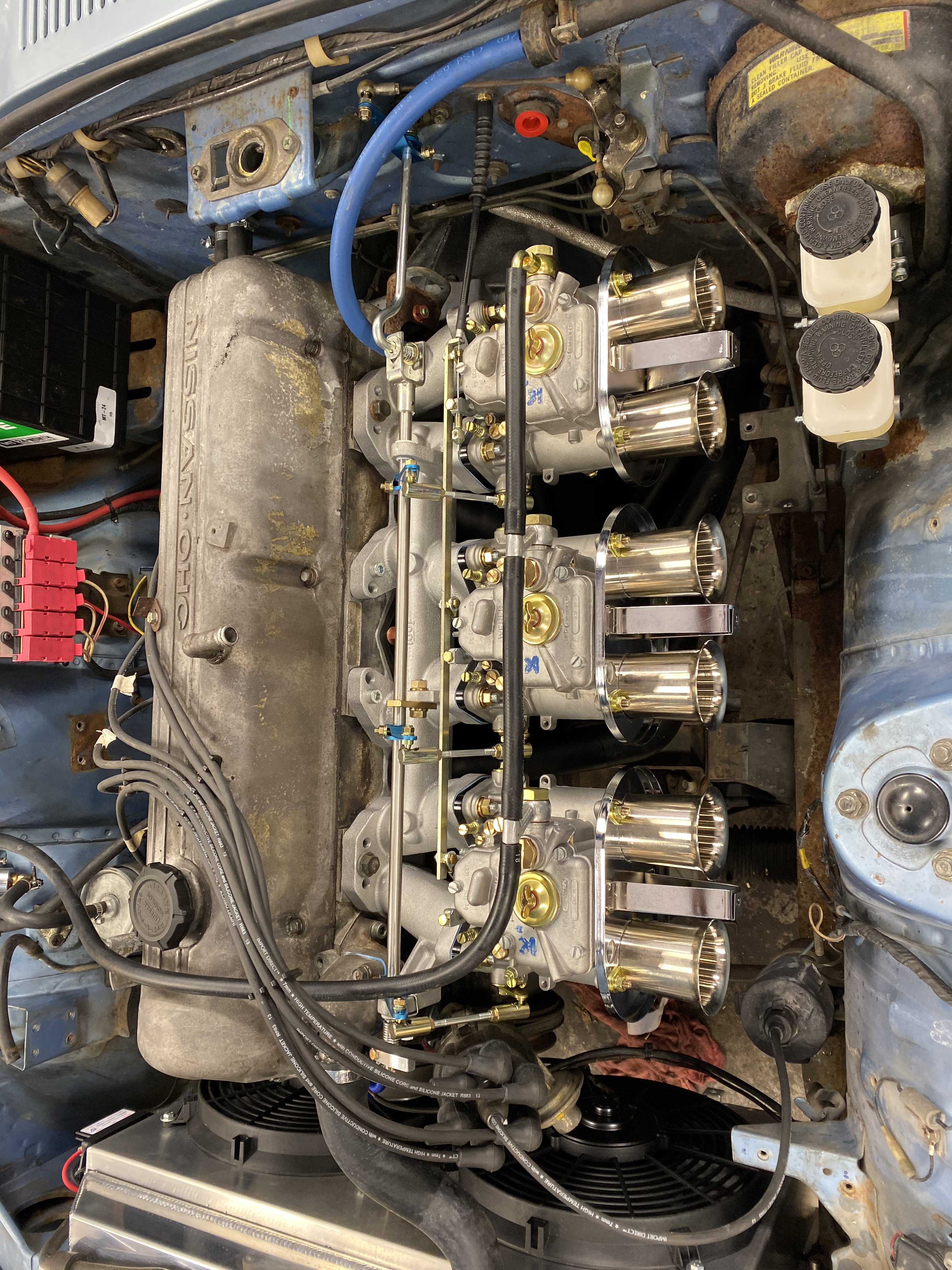
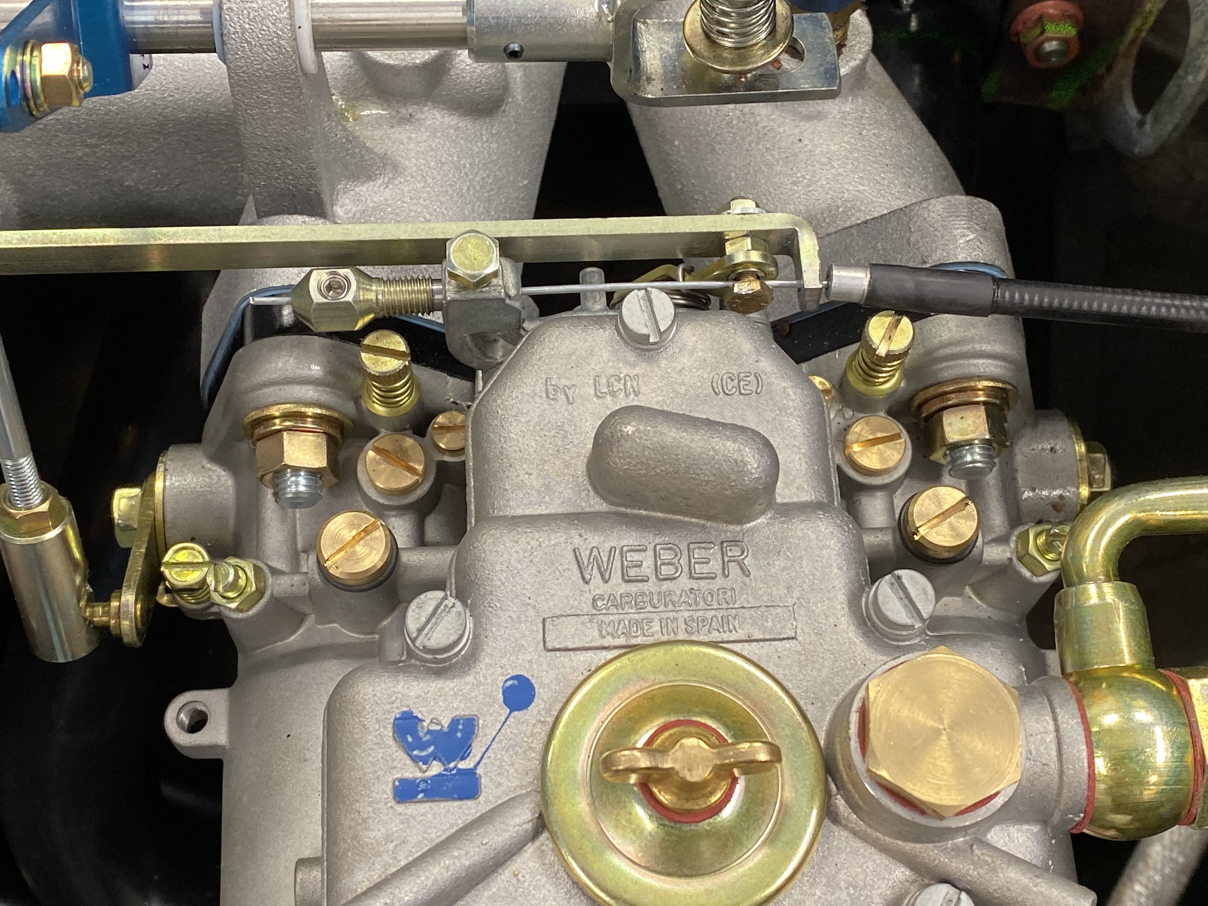
I am doing a big job for a customer at my shop and decided to take a different route with the choke action on triple 45’s. I have done the long cable around to the 1st carb and the lever/bell crank action on the 1st rod end but neither were as neat and clean as this in my opinion. Now I do have a set of right hand action N.O.S. Weber enrichment levers but I can’t stand to use them. I think this is the next best thing. I have a parking brake cable boot coming I will put on the nipple coming out of the fire wall and think I will add a cable receiver to the end of the link rod to make that look a little more finished but overall very happy with the way this came out. This car car is getting t3 front and rear brakes, wilwood master cyl, auto to 240sx 5speed conversion with aluminum driveshaft shop shaft, lowered springs. Shocks, 16” panasports, aluminum radiator with dual electric fans & dc controls continuously variable cooling fan speed controller. That is round 1. 605DA486-688C-4EED-8607-72BBA0D10B52.MOV
-
You should not solder. That makes the joint brittle not better. Crimp heat shrink and move on. No auto manufacturers solder the joint. And that’s not because it takes more time. It is understood that that puts a stress area in the harness
-
The powder coater I am using had a very well done l6 turbo valve cover done that had the box and turbo raw. He said he wiped the powder off prior to baking. Looked great. He is doing a jdm NISSAN valve cover for me that way. We’ll see how it looks