tioga
-
Posts
145 -
Joined
-
Last visited
-
Days Won
3
Content Type
Profiles
Forums
Blogs
Events
Gallery
Downloads
Store
Everything posted by tioga
-
Since you already have a intake collection like me just add the jenvey to the Harada and Sk you already have. I am inquiring if they can make it in the same black paint as the bodies.
-
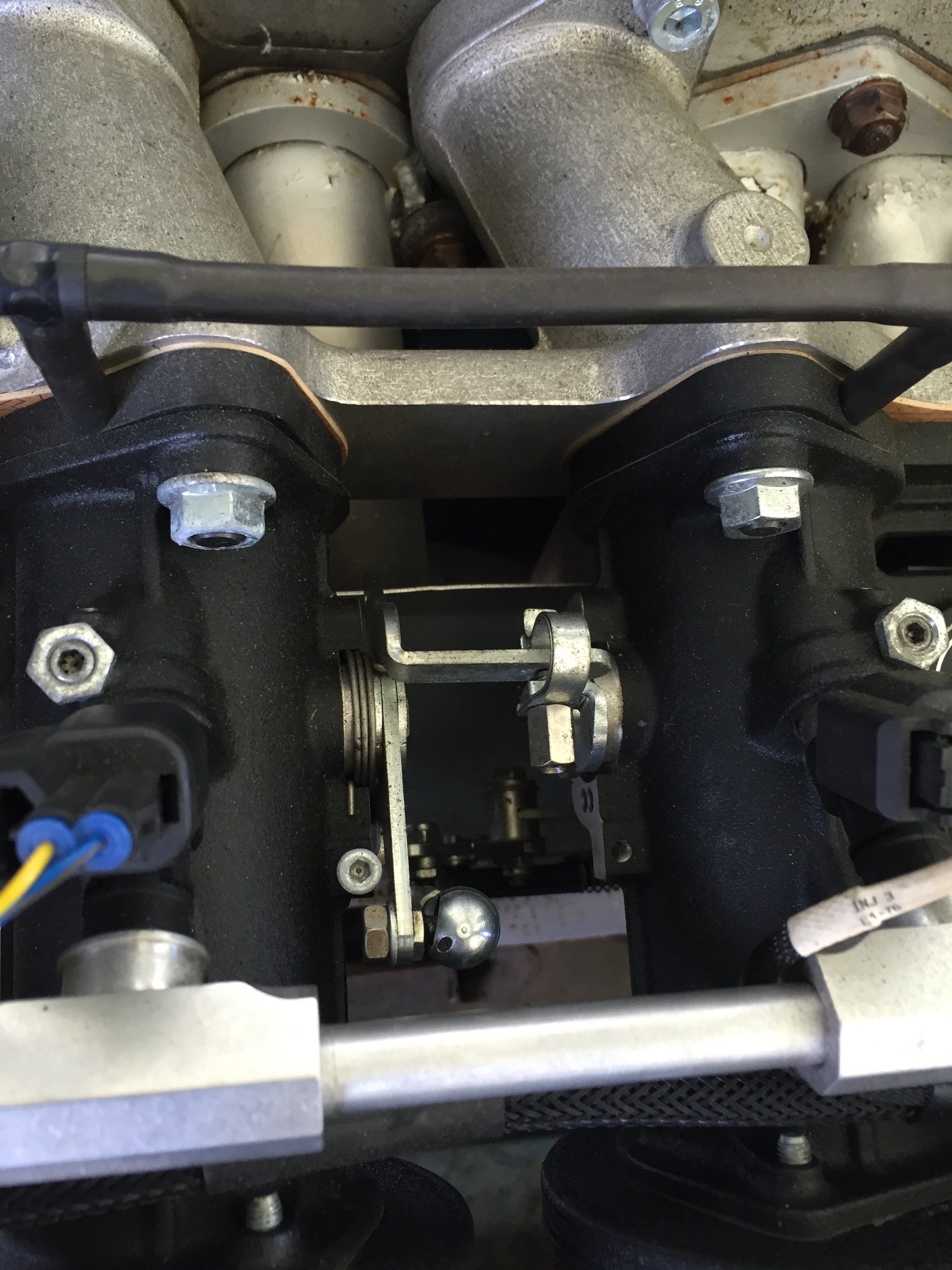
If you look at the body in that diagram it is not the same as my body and from your pic not the same as yours either though it’s hard to tell from your pic. These are the bodies in the pic I told you to look at on the jenvey site with the Ginetta badge. Note the parallel air bleed passage and the extra Allen at the air horn end. Our bodies have a angled passage for the air bleed. Take a close look.
-
I have seen that too that’s why I ordered the ports. You put the damn ports in Cap off each one so they are allowing zero air in and the car idles high. Loosen the throttle stop screws so the throttle plates close al the way down still too high. It makes perfect since if you think about it. Since these nipples only install just a short way in the body you have the air bleeds wide open and they pass a lot of air.
-
I can send you about 10 emails back and fourth over the last few weeks trying to get the guy on the other end to understand the problem. He kept telling me I can balance with the butterflies! I finally had to yell at him and tell him I am not asking how to balance with the nipples in. I am a 50yr old shop owning mechanic and have had these t-bodies running for over 4 years. Go ask your engineer how to block the air from the air horn side of the butterfly. He apologized and said he would send it to engineering. I assumed when I ordered them they would block that passage and hoped they would seat the same way as the adjuster screw only with a hole down the middle. This design would allow you to cap off the ports, balance the bodies and then when open allow you to add a idle kicker for cold start. I will say that a timing map with about 25* of advance at 500rpm and 10* at target idle (800 rpm in my case) 5* at 1k RPM. produce a great timing based constant idle system that is what I have been using for years and idles well on cold start. You can also tell I’d you idle air is set right by just looking at the timing the ecu is running at idle. If it’s running at 15-20* you need to open the plates a bit
-
Time-sert as grannyknot says. Make sure you get a insert that goes as deep as possible but still allows the expander to be used. The inserts come in many different lengths. I would be looking at bolt length and proper washer as mentioned above. Put the bolt in with no washer and make sure it goes in deep enough that when the washer is added the bolt definitely does not bottom.
-
I have been running a Ka bolt and I believe three washers. This gives more bolt shank not engaged in the threads to stretch and holds well. I turn over 7k on a daily basis with no problems.
-
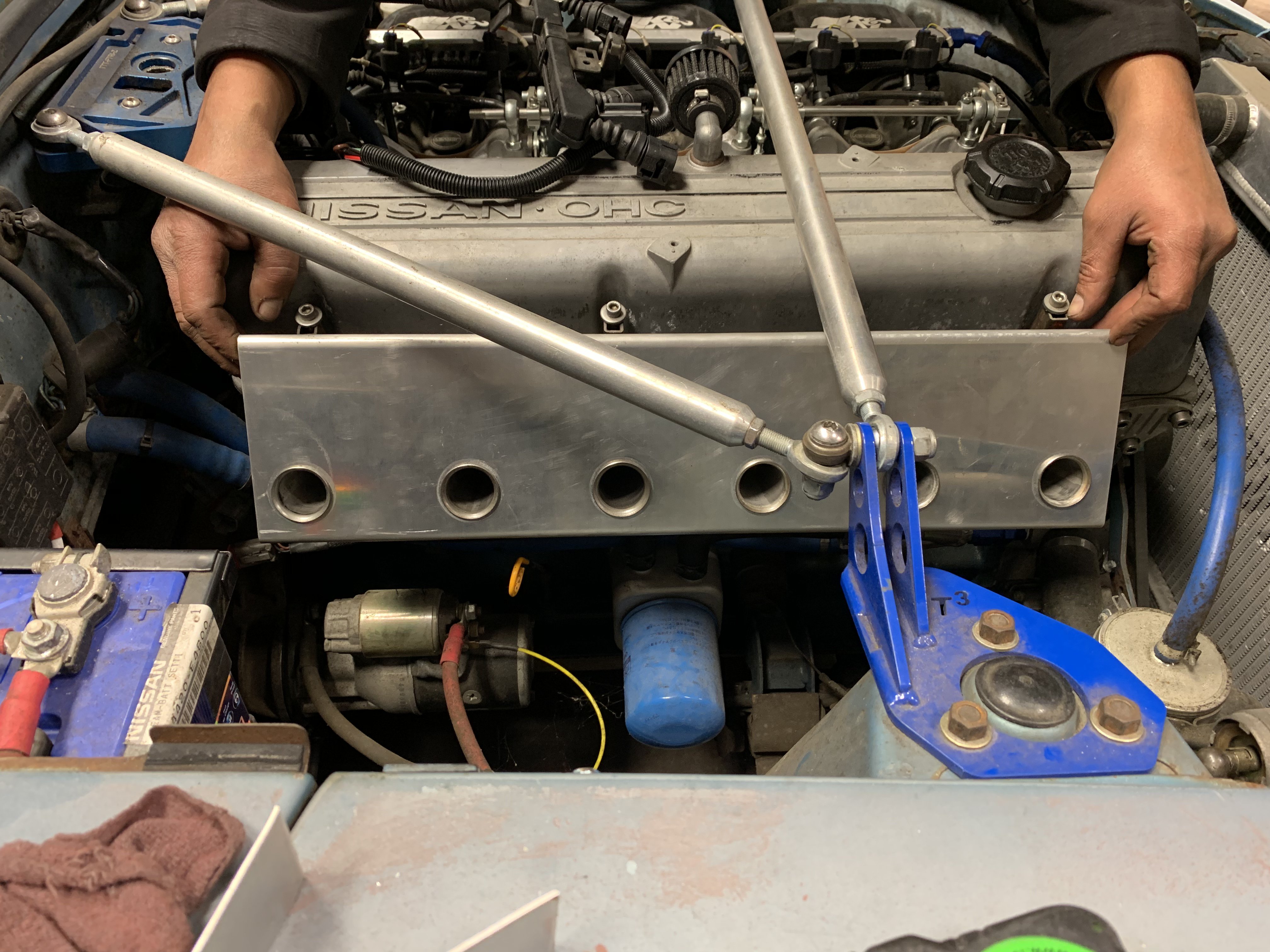
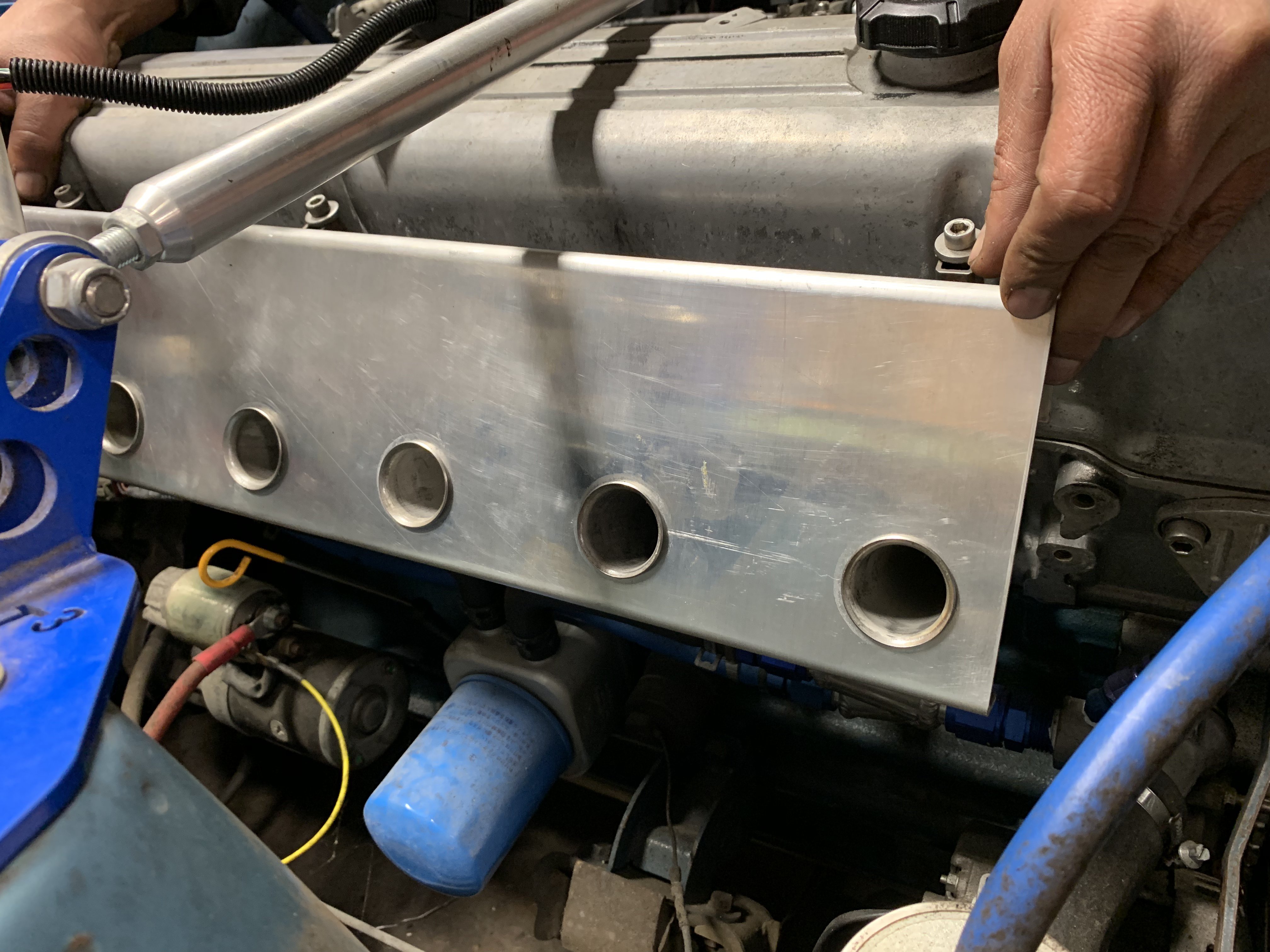
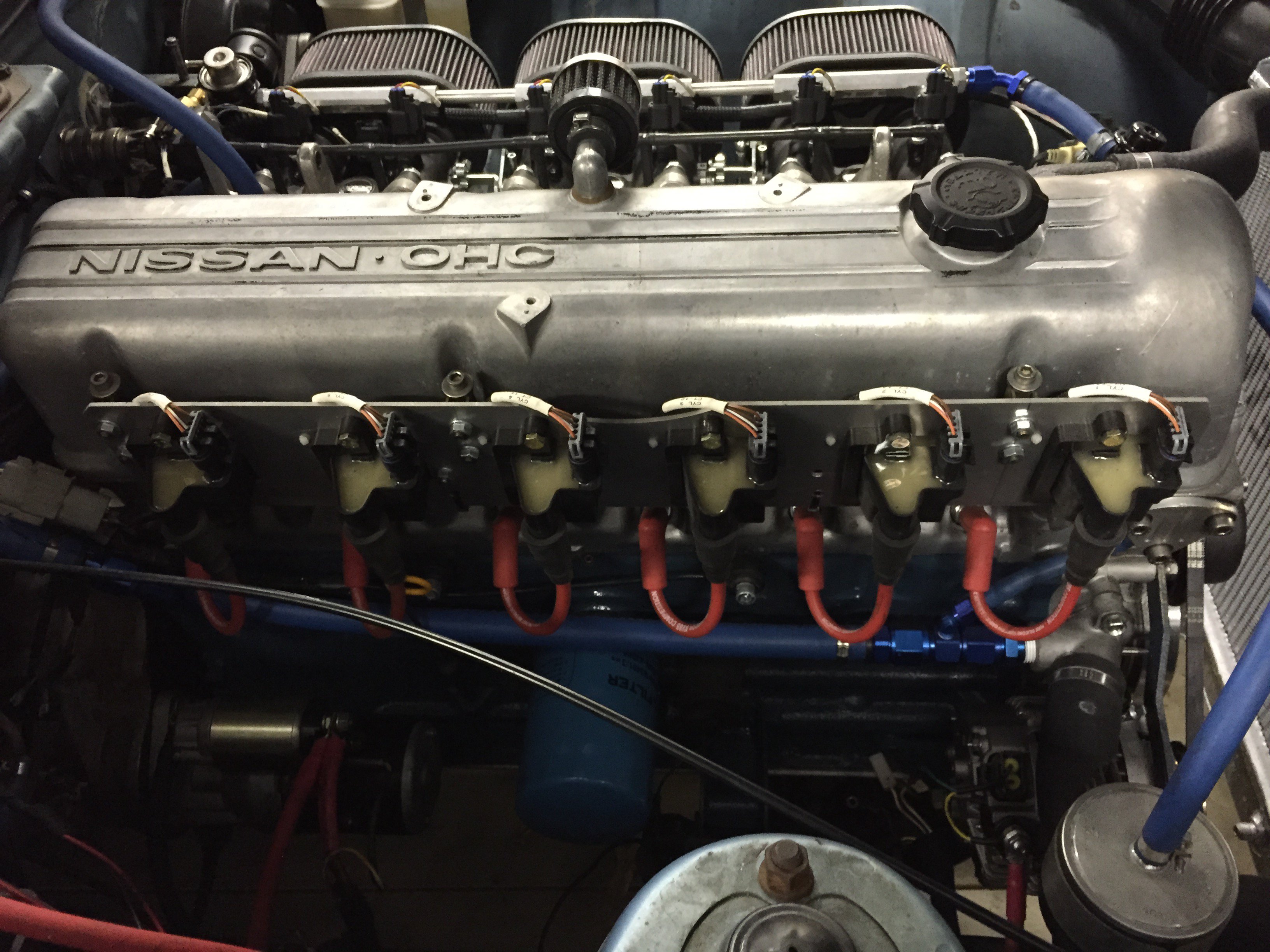
Here is my coil bracket. I had a Rf noise problem that took forever to figure our from my LS coils, I made this coil bracket with shielding all the way down to the plug. Immediately fixed the

-
I am not running a manifold reference for the fuel pressure regulator but with a map sensor and FUEL pressure sensor my ecu calculates relative fuel pressure from that info. This is what the modern production fuel systems are doing and is more accurate than the referenced fuel pressure regulator.
-
Those ports cannot be used unless you block the passage to the air horn side of the t-body. They are intended for balancing within the body. (Bringing up the throat that lags behind if you have one.) Thus there is a passage from one side of the butterfly to the other. When you pull out the adjust screws and put In the nipples they sell at jenvey you open this passage completely and even with completely closed throttle plates it will idle too high. The bodies on their site that have these nipples in them have a different design casting with a Allen plug at the air horn side of the passage as well. I suspect you can use this to block the passage. I am currently discussing this with them and they seem in the dark about this. You could epoxy the air horn side of the passage. I am considering this but hate too. In reality they are very well balanced butterflies by them selves. I only have one of the adjusters cracked open to balance right now and it was only very slightly off. If you look here and scroll down the bottom. The black dcoe body that says Ginetta on it has the ports installed and you can see what I mean. https://www.jenvey.co.uk/products/#oem-solutions. Jenvey’s intake has ports in line on the bottom hidden from sight. Oer also sells a phenolic spacer with a nipple on each port.
-
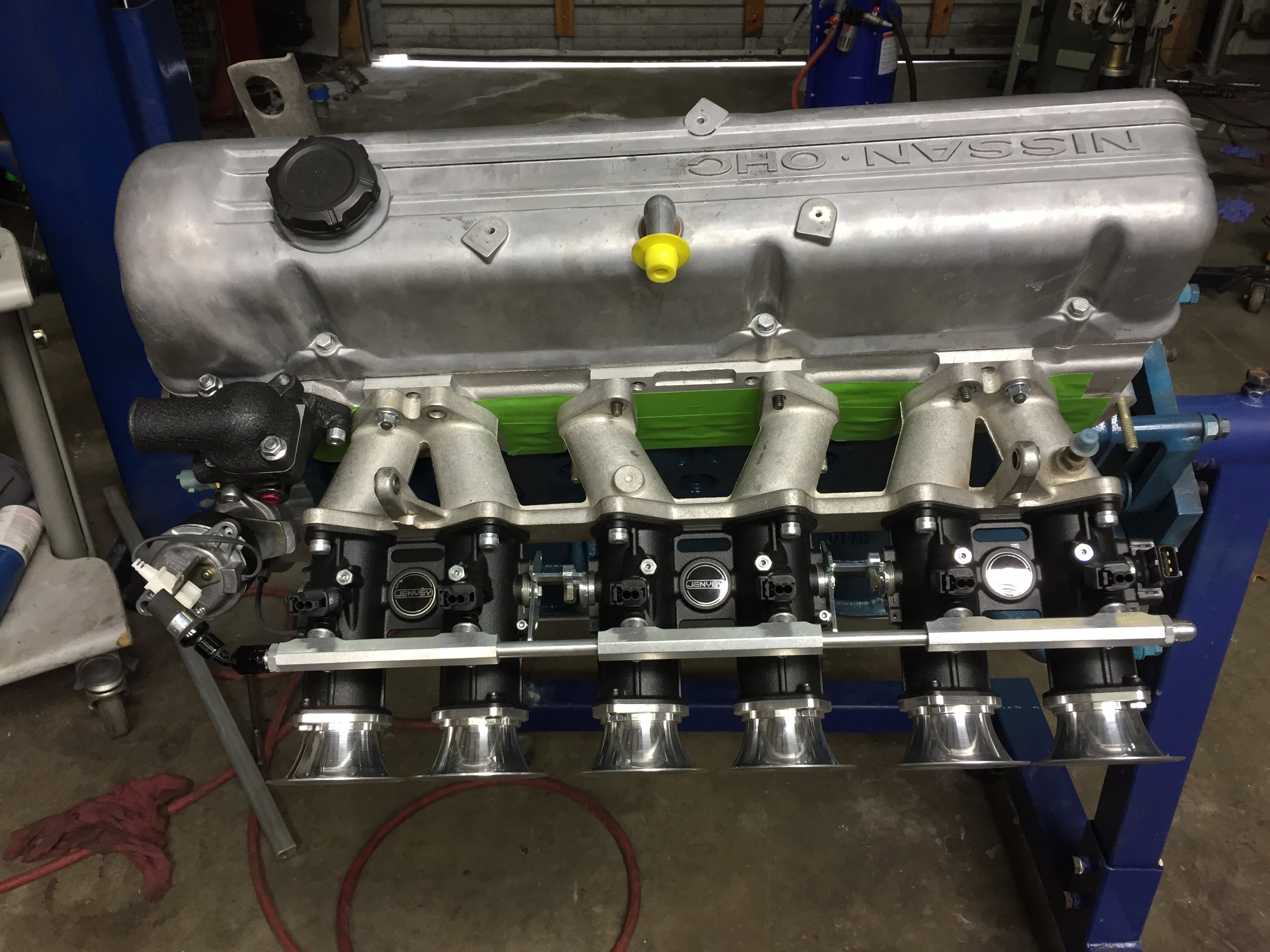
I would recommend the jenvey over the oer t-bodies. The jenvey are extremely well made. Everything else looks chunky and crude after you have a set of the jenvey s. They also have a nice intake now too. With the turmoil over there right now the dollar is strong. I’m hoping after the brexit disaster next month to get a Revere carbon air box for a more reasonable price.
-
Can I see some pics? Firm on price?
-
Looking for a z’s p82 intake if anyone has one. Can pay cash or if you want a different intake I prob have it. I have n42, n47, etc and a couple triple intakes.
-
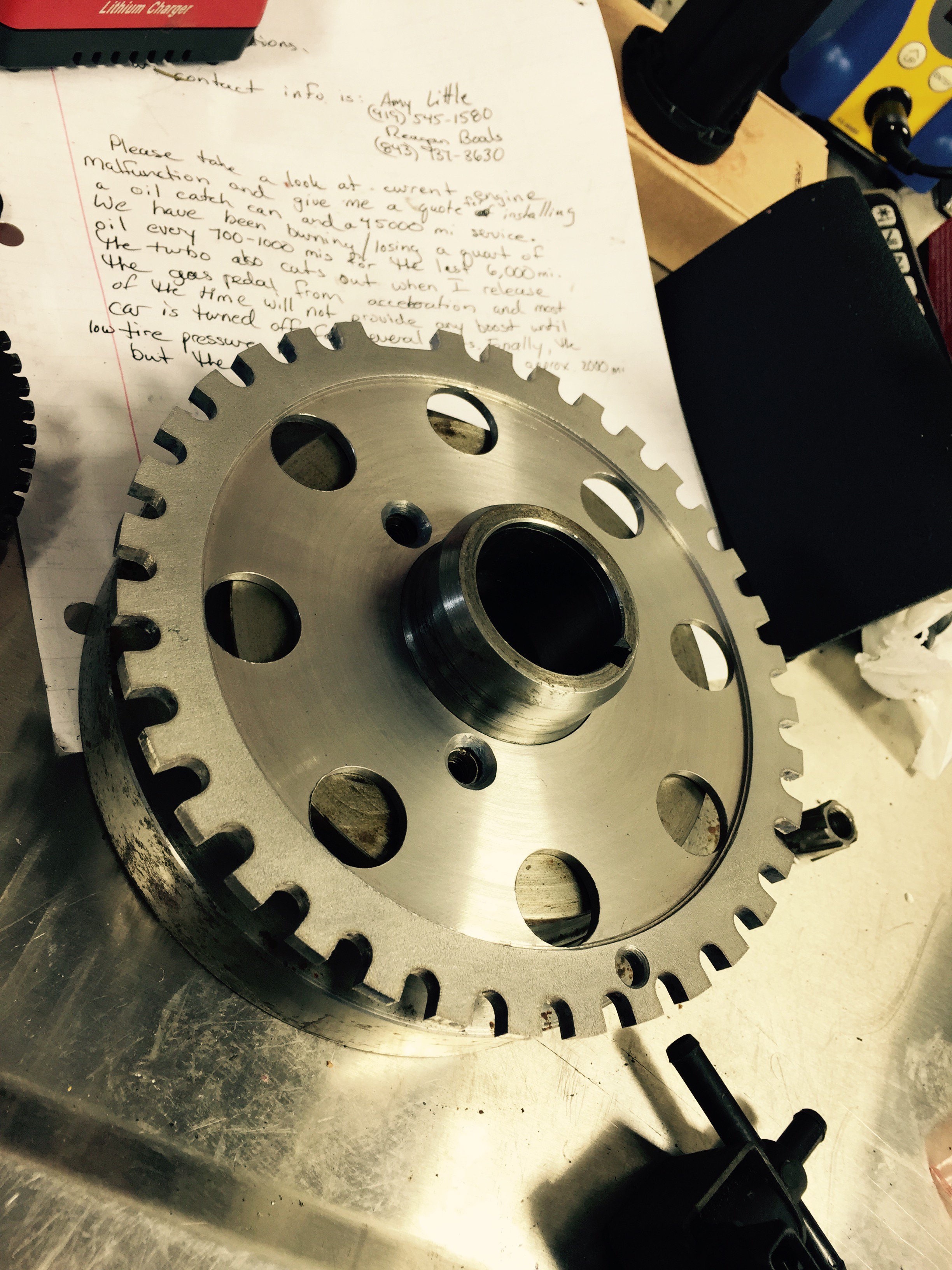
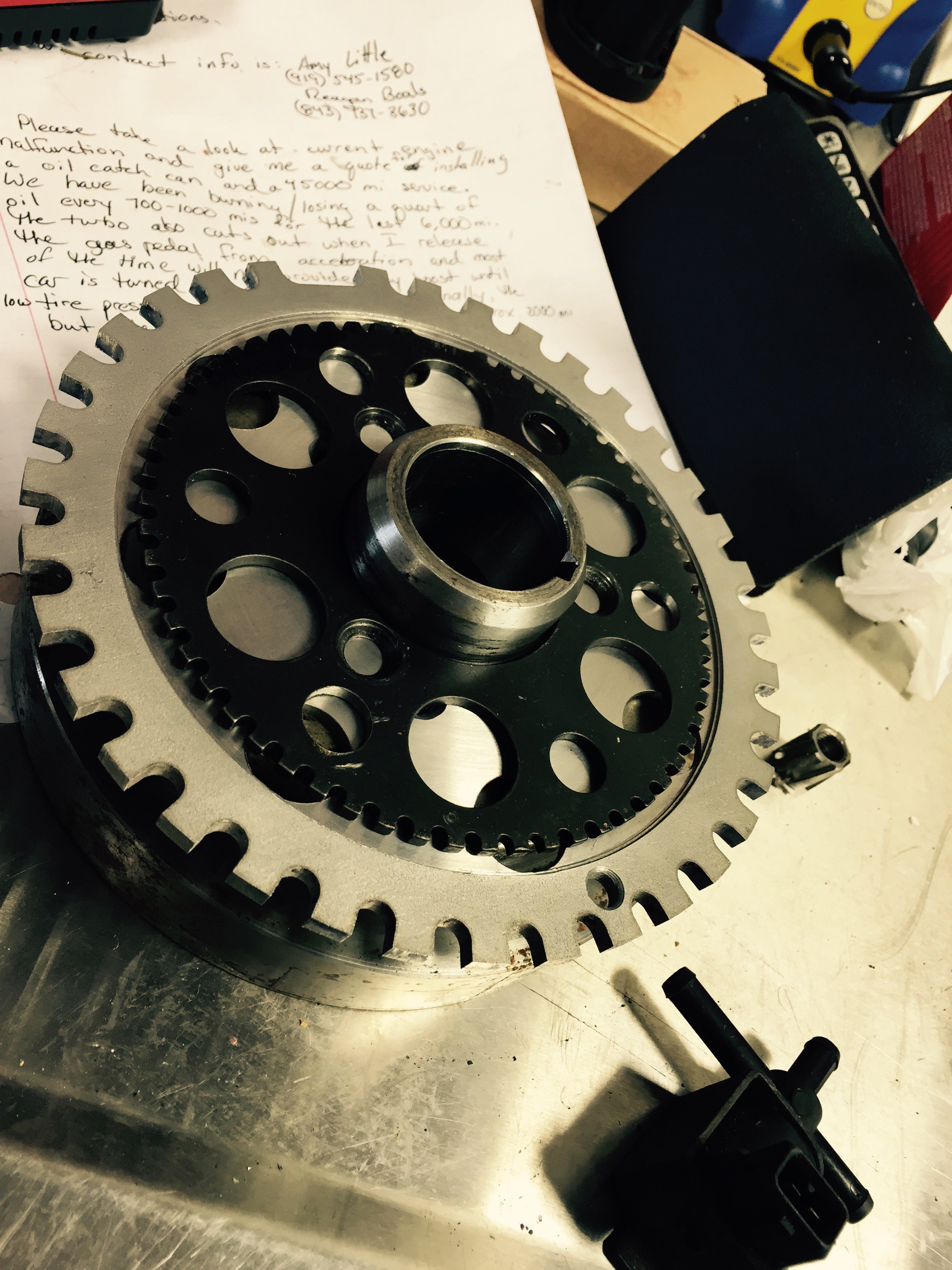
I am running a similar 5mm wheel and I turned it down thinner on the lathe for clearance. I also had the small rabello wheel on my damper and it’s holes were countersunk already.
-
Misfire /breakup and high rpm with stand alone AEM infinity
tioga replied to tioga's topic in Nissan L6 Forum
Never check the back three with a light. Yes load made a difference. Less throttle higher I could rev. This made it impossible to check timing at high rpm and see if it was moving around because it wouldn’t do it. -
Misfire /breakup and high rpm with stand alone AEM infinity
tioga replied to tioga's topic in Nissan L6 Forum
When you look at OE coil setups they are usually buried in a tunnel in the head which is it’s own shield and when not like on the newer plastic valve cover n52 bmw motor where a good portion of the business end of the coil is surrounded by plastic there are metal inserts in the valve cover that are sourrounding the coil. These fit in the head and up through the v/c. They are grounded where they push into the head. They didn’t add these for the hell of it.
-
Misfire /breakup and high rpm with stand alone AEM infinity
tioga replied to tioga's topic in Nissan L6 Forum
In reading about automotive Rf interference it is known that flat plains of metal are never good. That is hard to avoid when trying to mount 6 coils for a inline 6. When you think about the intended use of these coils there are only 4 beside each other then on the other side of the motor 4 more. That seems like that might make the noise issue occur at a higher rpm than 6 beside each other. Maybe not but something to think about. -
Misfire /breakup and high rpm with stand alone AEM infinity
tioga replied to tioga's topic in Nissan L6 Forum
First were D581’s, and second set were D585’s -
Misfire /breakup and high rpm with stand alone AEM infinity
tioga replied to tioga's topic in Nissan L6 Forum
Not yet. Just drove the one day but many trips to 7,500+ so feel confident the problem is gone. I have never been able to get past 6k wide open before. Been raining ever since I installed but I plan to open the gap back up. I also need to fine tune the upper end of my fuel map. My VE table is just extrapolation in that area since I could never get there. -
Misfire /breakup and high rpm with stand alone AEM infinity
tioga replied to tioga's topic in Nissan L6 Forum
My CAS is also on opposite side but damper end. -
Misfire /breakup and high rpm with stand alone AEM infinity
tioga replied to tioga's topic in Nissan L6 Forum
It did not show up when scoping the crank sensor Mag and Hall effect sensors with wiring run outside the engine bay did nothing to help. AEM showed no crank errors. It seems like the coils were self triggering. And yes I am sure the dwell was correct and tried various dwell settings from low to high as well as spec for the coil used. -
Misfire /breakup and high rpm with stand alone AEM infinity
tioga replied to tioga's topic in Nissan L6 Forum
Your design down low may help. I am running two knock sensors down there and chose to move up for that reason. ‘Yes the motor would start to pop and backfire at 6k like the timing was erratic. This first led me to thinking I had crank sensor issues. -
Misfire /breakup and high rpm with stand alone AEM infinity
tioga replied to tioga's topic in Nissan L6 Forum
Seems like it but did not. I did when trying to isolate the problem wrap everything in aluminum foil attached to ground. Remaking my harness with twisted pairs, Rerouting my harnesses away from possible sources of noise etc. This did nothing for the problem. The bulk of the aluminum is to get me a mounting surface lined up with the plugs. The business end is the tube the coil is housed in. And maybe just this coil would work on its own but you need a way to support it and these coils are designed to simply push in the head so the tube solves the mounting issue while adding a shield at the same time. The reason I posted it was because it was a strange and persistent problem that many simple efforts of correcting did nothing to help. This leaves you questioning everything. I was simply trying to share my experience so someone else might find the solution quicker than I did. There are people selling a bracket for the LS coils just like mine. I am not saying that you should not use that bracket or the coils but if you run into a strange problem with it/them then maybe you will remember this post and find your problem where I did. I own a European auto repair shop and have been professionally repairing European cars for 30+ years and have owned and built 70-78 z cars longer than that. I can tell you this was a very difficult problem to figure out. You have to take into account that when you encounter something like this it is not just something that pops up on a running engine. You have likely just changed a large amount of parts going to a complete stand alone system as I did or just a ignition system. New ecu, new harnesses, new crank and cam sensors, fuel delivery system, new ITB’s, tps, etc. and in my case a new motor plus the tune you are working on . This leaves a lot places to look for the cause. -
Misfire /breakup and high rpm with stand alone AEM infinity
tioga replied to tioga's topic in Nissan L6 Forum
My last coil design was to get the Most noise rejection as possible. (RF and electro magnetic) Heat was not a issue. The coils I had used before were genuine GM and Denso. Both reputable brands and exactly the same problem. Plug wires were custom made magnicore and a set of NGK off the shelf corvette wires. Numerous different spark plug types were explored. The fact that the amount of coil output determined the onset of the problem, power supply and ground as well as failed components were eleminated, coil output more than enough to make the power we are making leave us with a noise interference problem. -
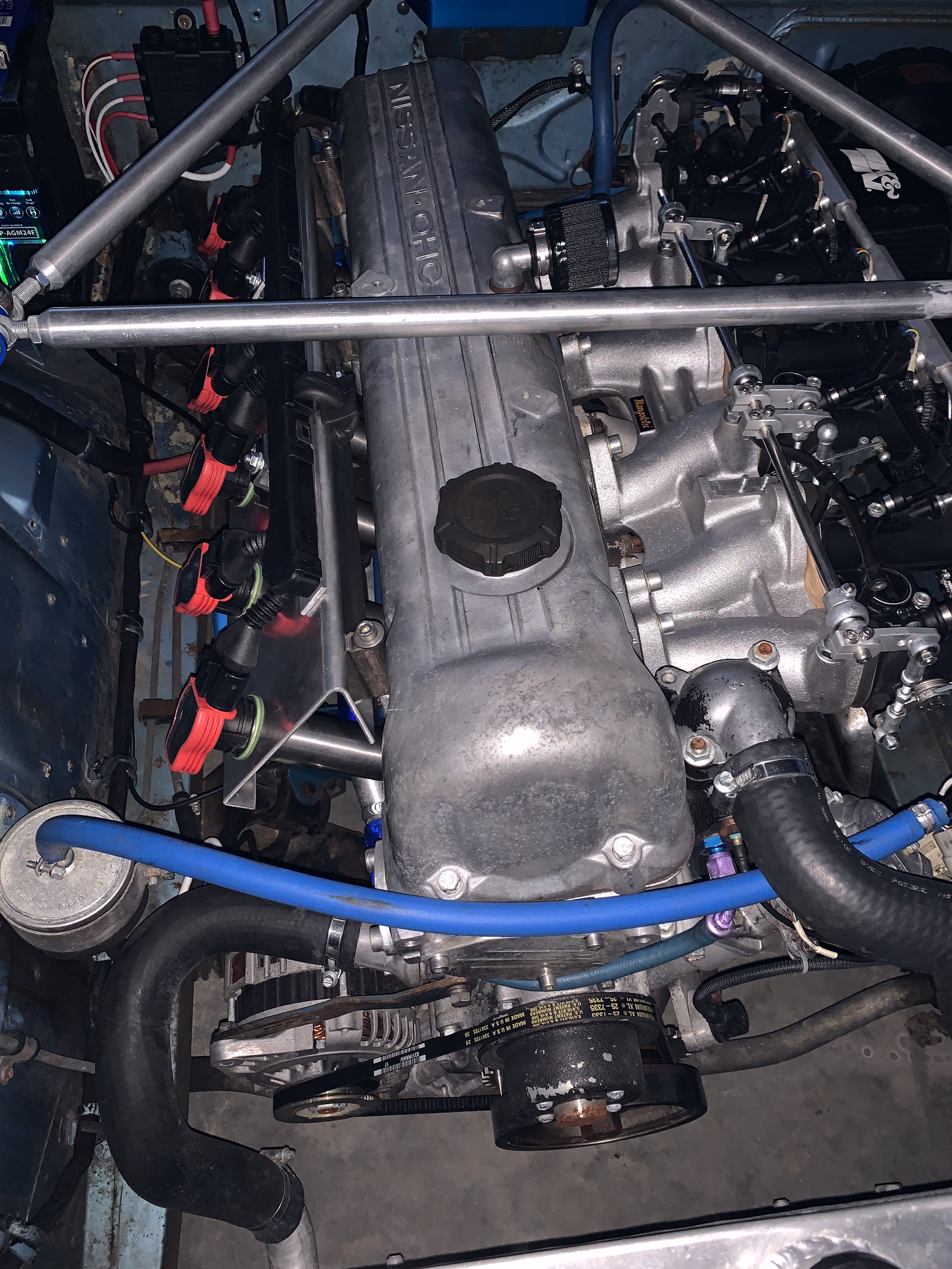
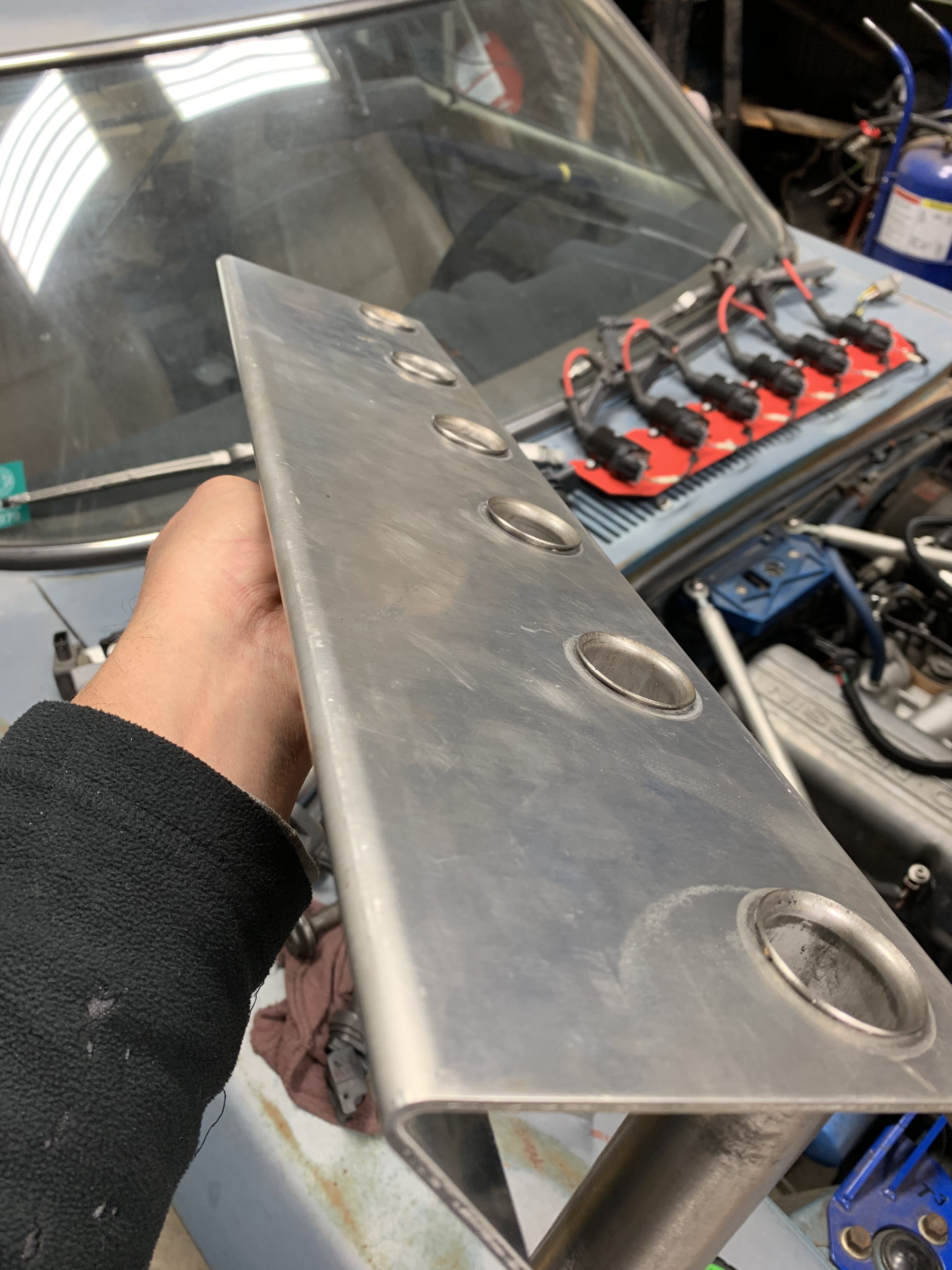
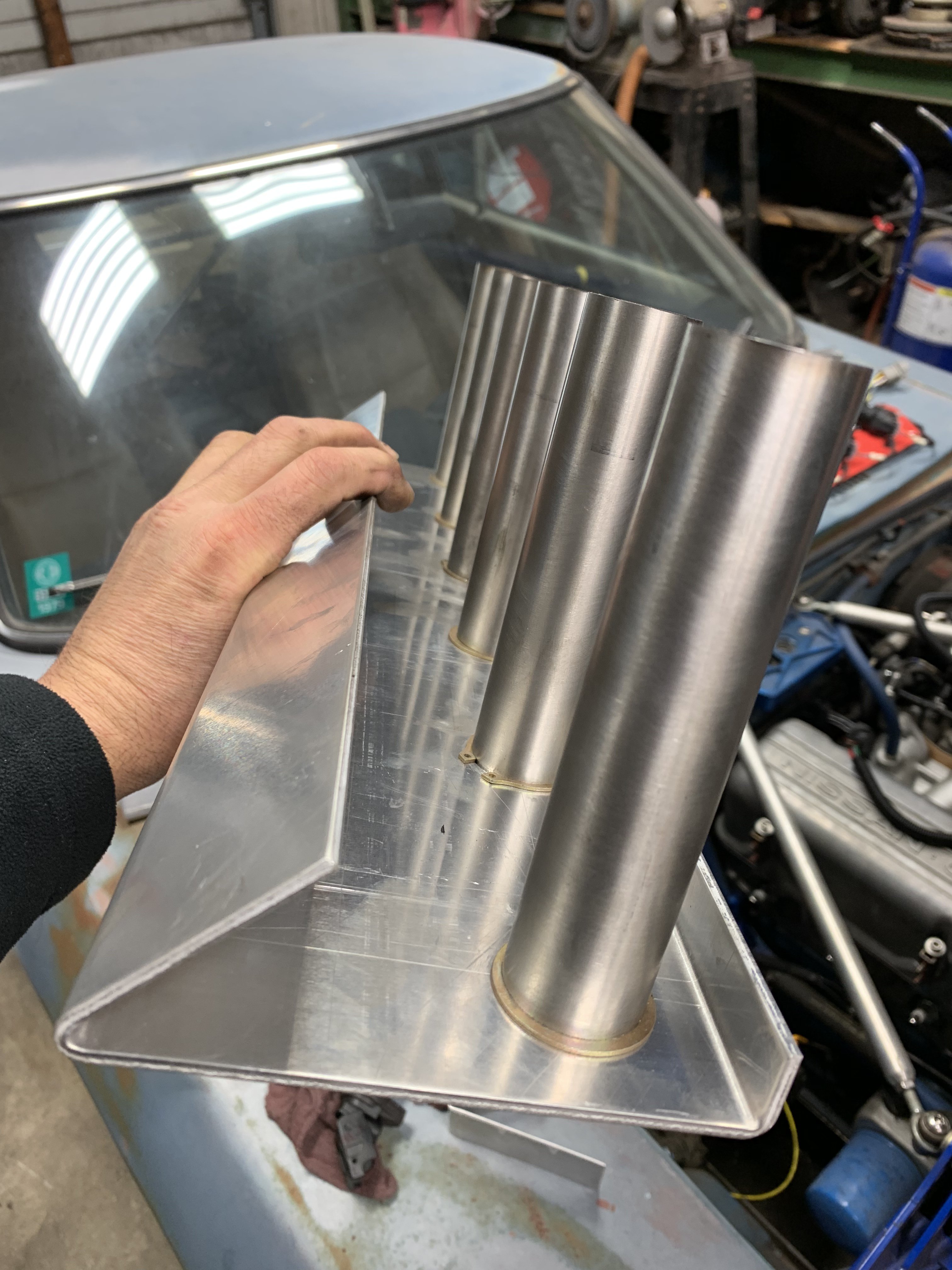
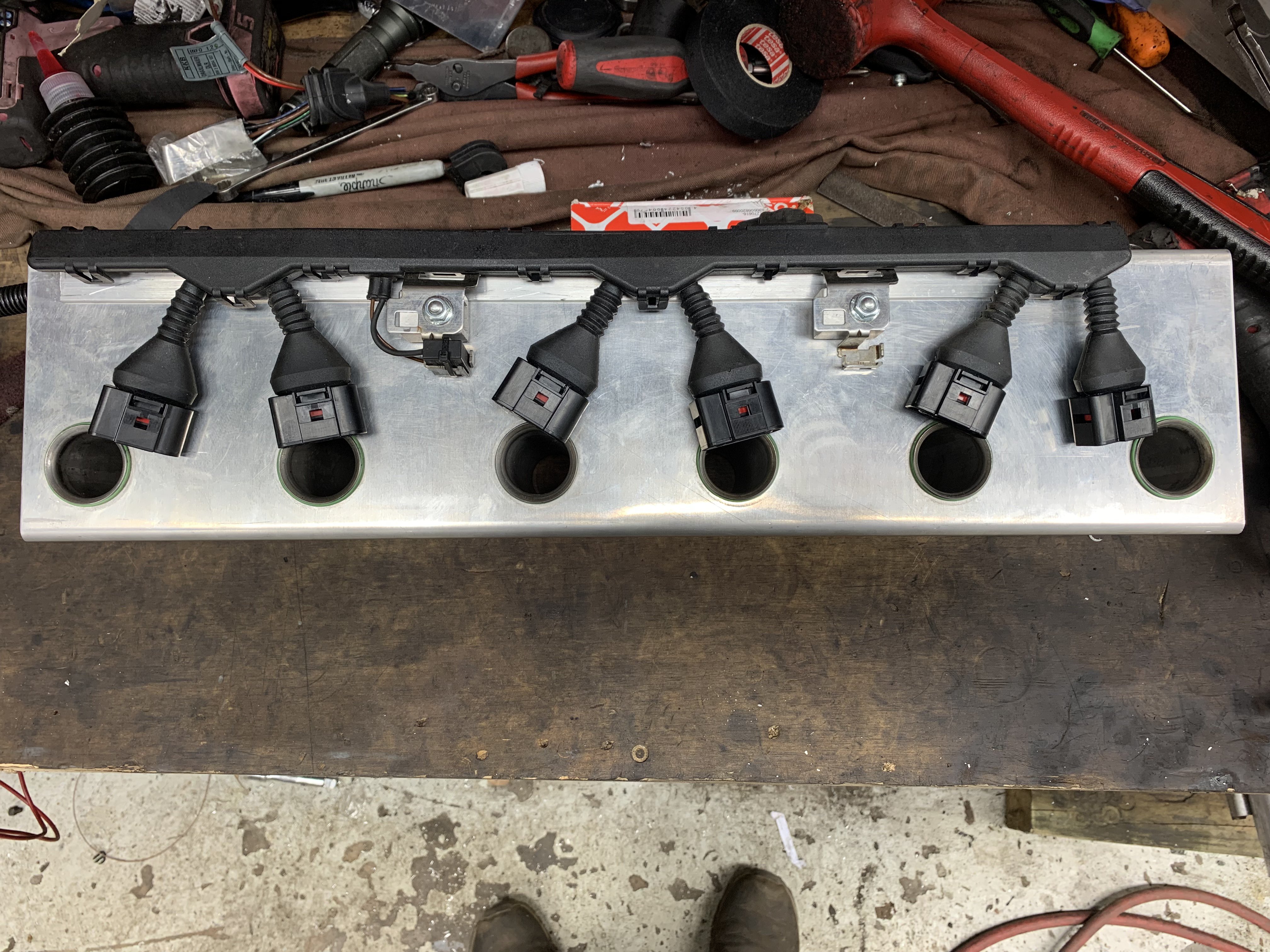
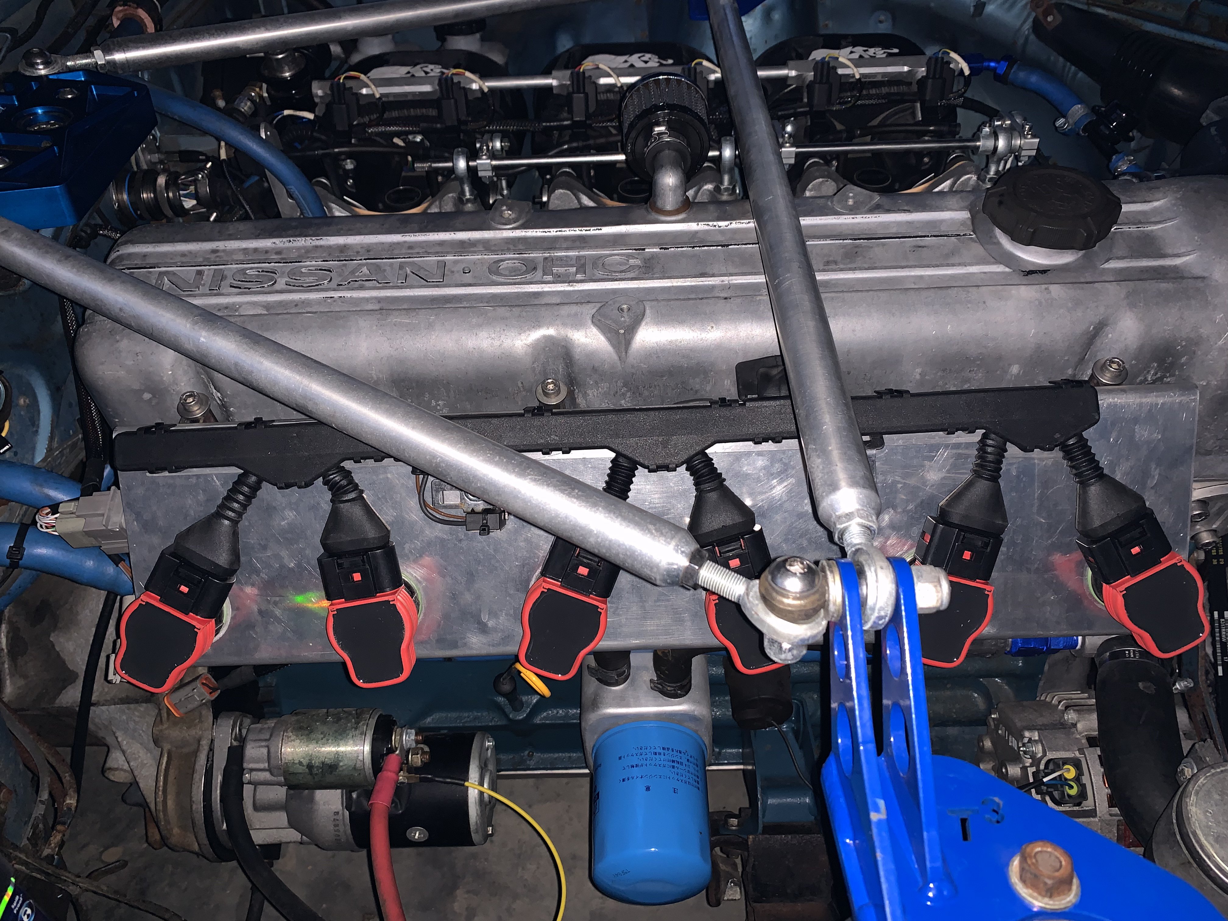
Just in case someone else has this same problem I thought I would share my problem and solution. I have a 3.0l with itb’s GM LS indivual coils and am running a 60-2 tooth wheel on the crank with a Hall effect sensor and single window reluctor in the old distributor housing for a cam sensor. This setup ran great to 5-6k the more load the lower the problem would occur like a secondary ignition problem but not a ordinary one. No amount of new plugs, coils, wires, harnesses would have any effect. The only thing that did was closing the plug gap down to a very small gap and I could see 6k but no more. The LS coils I was using are known to be good for 1,000hp turbo cars so no reason I should see problems on a 300hp NA motor. Finally I made yet another coil bracket this time using coil on plug coils and using a aluminum bracket with stainless tubes press fit in that run all the way down to the plug. This shields the coil just like OE setups where the coil is in a plug well surrounded by aluminum. Fired it up today and 7,500 with no sign stopping. Pulls hard as far as you want to twist it. In photo two you can see sitting on the cowl the last coil setup I had and the last photo shows a even earlier version.
-
Twin cam head for the L6 from Derek at Datsunworks
tioga replied to Derek's topic in Nissan L6 Forum
Seems like the channel in the valve cover is asking for the plug wires to be reversed and the bundle come out the back and over the starter. Then we could better see your valve block and hard lines.