

JMortensen
-
Posts
13742 -
Joined
-
Last visited
-
Days Won
68
Content Type
Profiles
Forums
Blogs
Events
Gallery
Downloads
Store
Everything posted by JMortensen
-
Note post #7: http://forums.hybridz.org/showthread.php?t=97185 10.84 @ 128.62. I don't think I can compete with the other guys John C mentioned. I'm down at least 10% displacement since they're all running strokers. My engine is really not too bad for something I built in my garage though.
-

East Coast vs. West Coast setup?
JMortensen replied to wheelman's topic in Brakes, Wheels, Suspension and Chassis
I was able to carry 4 250mm wide slicks in my Z. One rides shotgun, one in the spare tire well, one shoved all the way to the passenger side of the hatch, and one all the way on the driver side. The hatch would just barely close, and there was enough room in front of the strut tower bar for a small tool box and a helmet. Jack fit underneath the top layer of tires. It's tight, but you can do it... -
rear poly bushings on outboard end of CA
JMortensen replied to blueovalz's topic in Brakes, Wheels, Suspension and Chassis
That's not a bad idea, but I did already modify the diff mount, and the stock crossmember has exhaust clearance. I think I'd like to work with what I have. I've had enough of the while I'm at its for a little while. -
rear poly bushings on outboard end of CA
JMortensen replied to blueovalz's topic in Brakes, Wheels, Suspension and Chassis
I guess the other option is to make a new strap from 1/8" steel. I don't want to weld the bearing holders to the uprights because I still want to use the toe adjuster. I'm thinking in the front I could just cut the crossmember off so that it uses the two bolts on the insides of the bearing holders, then weld a similar strap on the front to reinforce it. Box in the end of the crossmember, and it would be done. I'll have a look tomorrow and post some pics. -
Crossmember. Alsil has one for Ford installs, blueovalz has a modded crossmember in his car, mine has been pretty cut up and is now a K member. It's been done.
-
rear poly bushings on outboard end of CA
JMortensen replied to blueovalz's topic in Brakes, Wheels, Suspension and Chassis
Need opinions. It has become clear that hogging out the straps on the rear bushings is going to be iffy. It's hard to do, and they'll be pretty thin when they're done. I'm thinking since the bearing holders will be welded to the upper part, does the strap on the bottom really need to be there? I'm starting to think it doesnt and if that is true it would save me a lot of hassle. Likewise in the front I'm thinking that what the diff crossmember is really goint to be doing after this is done is taking the lifting load from the nose of the diff and putting that into the chassis. It won't be locating the front bearing holders, since they will also be welded to the chassis. So I am tempted to just hog the crossmember out so that it doesn't touch the bearing holders at all, rather than trying to get a precision fit. Still also considering welding the crossmember in. I think the way my car is set up I could pull the diff by disconnecting the front mount on top and then the studs that go through the mustache bar, push the diff forward then tilt it back and drop it out. Thoughts on any of this anyone? -
Post your questions in your own thread. Lets keep this one on topic.
-
Imagine if there was an LS powered car there...
-
R200 Short nose carrier into a R200 Long nose
JMortensen replied to Ericshere03's topic in Drivetrain
12mm carrier holes with 10mm bolts is not a problem. You can either clock the ring gear so that it rests on the side of the hole (sounds cheesy but it works) or if you're really anal like me you can make ring gear spacers. Just take 12mm OD 10mm ID tubing and cut into small pieces, slide over the ring gear bolts and now there is no more slop. The only thing about the spacers is you don't want to make them too long, or they'll prevent the ring gear from being tightened down against the carrier. Too short is not a problem. The other option is get a later longnose R200 diff out of a 300ZX or 240SX with 12mm ring gear bolts. I can't remember the dates, but they were produced from something like 85-89. A search should get the exact dates if you really want to do it right. -
You could do that, and it would be really easy to do. My point was that there is very little room to swing it out. Might have to see if I can squeek a little optimization in there. Thanks for the idea!
-
The Ultimate L28ET Guide/What you need for 350+whp!
JMortensen replied to Drax240z's topic in L-Series
ABSOLUTELY!!! You don't need to be an admin or a moderator to write a FAQ. If you see a need for a FAQ to address a question that constantly gets asked write it up and the admins will approve it. -
I'm not forgetting that, but that isn't the ONLY way to do it. Go take a look at your steer knuckles. It would be great if we could bend the ends out in order to get more Ackerman, but the brake rotor is right there. 260DET had his cut and rewelded to maximize this, but I don't think you can get more than about 1/4" or so of bend. On a rear steer car (rack or box behind the crossmember, not rear wheel steer) this is easier because you're bending the steer knuckles away from the brakes. My friend bent the knuckles in his 510 for Ackerman years ago, which is what got me interested in it in the first place. His car turns in way better than mine used to... we'll see how I fare with all this crap I've done. I agree, I don't think it does.
-
Question about dual master cylinders...
JMortensen replied to JMortensen's topic in Brakes, Wheels, Suspension and Chassis
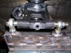
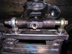
The benefit to this over a normal master with a proportioning valve is that this is ACTUALLY proportional and a valve really isn't, so you can get more rear braking (especially at high speeds) with this setup than you can with a traditional prop valve. I've decided that I'm going to do the same. Keep updating as it comes along. You'll probably save me some hassle... -
rear poly bushings on outboard end of CA
JMortensen replied to blueovalz's topic in Brakes, Wheels, Suspension and Chassis
Lessons learned: 1. Poly bushings suck. 2. If you're going to do this yourself, bolt the strut in tight, THEN you should be able to put the strut through the monoball. I think what I did wrong was I had the strut hanging from the monoball, then I stuck the bolt through and tried to adjust the shims to fit. I was surprised that the shims were so heavy on the rear, and I couldn't figure out why it wanted to be so far forward. When I redid it there is still more shim to the rear, but at least the strut comes straight thru the top. -
rear poly bushings on outboard end of CA
JMortensen replied to blueovalz's topic in Brakes, Wheels, Suspension and Chassis
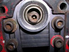
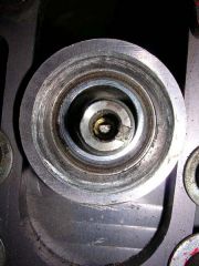
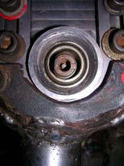
I did a little playing around today, and I think I've got this misalignment of the outer bearings thing handled. All I had to do was change around the shims on the bottom. What's more is I figured out that both sides were equally wrong, and in the same direction. So what that tells me is that my assembly job wasn't as bad as I had feared. What I did was to unbolt the top of the struts and look and see where the strut sat in the monoballs. Both were pressing against the leading edge of the monoball. So I changed the shims around to move the strut back. Now they are both centered in the monoball holes. Then I compressed the suspension with a ratcheting tie down strap (that's about the point where I wished I didn't have gas charged shocks) and both L and R sides stayed pretty well centered in the holes. Maybe moved .015 to one side or the other. That kind of side load is pretty acceptable I think. I was surprised, because the one side felt so bound up. I think it is just the polyurethane. I pulled the strut out swung it around and checked for binding in the rod ends on the outside, and it was pretty apparent that there wasn't any (strut would swing back and forth like a pendulum at least twice if you pushed on it). So I think I have the outside done to my satisfaction. Despite my earlier hesitation, this gives me a little more confidence in doing the inners. Some pics: Improper shim on bottom: Proper shim on bottom: Strut shaft offset to one side with incorrect bottom shims (doesn't look as bad as it really was): Strut shaft with correct shims: Strut shaft compressed with correct shims (see the movement?): The reason why the last two are upside down from each other is because I was spinning the car on the rotisserie to check preload on the rod ends and to change the shims around. -
-
-
-
-
-
I think you're barking up the wrong tree. Ideally you would just set it to what it needs to be and it wouldn't change much at all through the motion of the suspension. Making the suspension angles change MORE through the travel is going the wrong way I think.
-
I'm not sure about all of this Terry. I mean if you make the LCA perpendicular to the frame, that would LENGTHEN it, right? I mean, it would be farther away from the centerline of the car if it was directly perpendicular to the centerline of the car. That would increase camber. As far as caster, I don't think the caster changes at all by moving the inner LCA pivot. Caster is determined by the angle between the strut top and the ball joint. Lengthen the TC rod and you move the ball joint forward, this changes the caster angle. Maybe as you said, it changes just a gnat's ass. As far as the Ackerman, I think you have that part wrong. My understanding is that the closer the rack is to the crossmember, the more Ackerman you'll get. This is because of the angle of the tie rods relative to the steer knuckle, and the "cam" effect if you want to call it that of the tie rod as it gets pushed and pulled from that angled tie rod. I hope that is correct, otherwise I spent a lot of time and effort screwing up my crossmember adding anti-Ackerman (moved the rack back 7/8" relative to the crossmember).
-
Actually, shouldn't it be the caster that changes the Ackerman more than the spacing of the LCA? More caster, end of LCA moves forward, steer knuckle is farther forward relative to the rack. Right?
-
I'm trying to get my LCA's perpendicular to the centerline of the car (they were previously angled forward quite a bit due to increasing the caster. So if you run a lot of caster, that means that the spacer in front needs to be smaller. In my case the spacer in front is going to be pretty darn small, and the spacer in back is going to be longer than stock. I hadn't thought of how that would affect Ackerman before now, but it seems like the further forward the arm is the more Ackerman you would get.
-
Rough Ride on the street
JMortensen replied to v80z's topic in Brakes, Wheels, Suspension and Chassis
Standard Z strut has ~6 inches of travel. Put a zip tie on the strut shaft right down at the bottom with the wheels in the air. Set the car down and roll it around to settle the suspension. Jack it back up. That will tell you how much sag you have. From there you can pretty well figure out how much bump and rebound you have.