

JMortensen
-
Posts
13742 -
Joined
-
Last visited
-
Days Won
68
Content Type
Profiles
Forums
Blogs
Events
Gallery
Downloads
Store
Everything posted by JMortensen
-

Billet Ali Rear Subframe
JMortensen replied to BlackBeaut's topic in Brakes, Wheels, Suspension and Chassis
A couple points: First off is the fact that even with AZC arms, you'll still have poly bushings on the inside. Cary wants no poly ANYWHERE, and with good reason. For a race car, it isn't a problem to have no bushings and the lack of stiction in the suspension means more accurate movement and less bind. For a street car, different story. Second, it should be fairly easy to convert a normal rear control arm to monoballs, but I've never seen it done. I know there are kits to replace the stock bushings in 911 semi-trailing arms with monoballs, so I know it is possible and I'm pretty sure I understand what is involved. Basically you just have to machine a monoball holder that fits the bushing cup and rides on an axle. The outer axle would be easily made with a 5/8" bolt, maybe even the stock spindle pin could be made to work. The inner pivot is larger, might be 3/4". I remember Terry had messed around with cutting the inner pivots off the stock control arm and then welding a big bolt into the stock control arm. I think that was a 3/4" bolt, but I'm not sure. He was already 1/2 way there though. Just weld in those bolts, make spacers, slide the monoballs in and bolt the spacers into the bushing cups. Viola. As to my setup, when I first bought my Z I had a close friend who worked at a Z shop do ALL the initial work on my car. At the time I hadn't been wrenching for a while, and he was the expert on Datsuns. When I just took all this stuff apart I found that I had GMachine inners and stock rubber outer bushings. So I haven't been running poly in the back on the outers, much to my surprise. Regardless, I am confident that the bushings won't be significantly bound at my 3/16" setting, because the toe change will be handled by both the front and the rear bushings. So 3/16 = 3/32 per side, and that = 3/64 deflection per end. I've seen poly bushings last a VERY long time under much worse conditions than that. I'm going to stick with poly because I don't have the means to manufacture the necessary spacers to run monoballs on the control arms. If someone made those spacers I'd run the monoballs, but it wouldn't be for fear of wearing out the bushings. -
Billet Ali Rear Subframe
JMortensen replied to BlackBeaut's topic in Brakes, Wheels, Suspension and Chassis
That's what I meant. I don't know if Cary was on the same wavelength. It still appears to me that you'll have an interference issue with the mustache bar and the uprights. Which got me to thinking about the mustache bar. You could eliminate the stock bar, and integrate a more modern design of a shorter bar into your framework. You'd need to beef the frame up on top I think, but the other advantage would be that you could move the diff forward, giving better weight distribution. As long as you're running CV's in back the halfshaft misalignment won't be a problem. Making the subframe instead of modifying an existing setup gives you so many possibilities. Talk about "outside the box"... -
Billet Ali Rear Subframe
JMortensen replied to BlackBeaut's topic in Brakes, Wheels, Suspension and Chassis
There's a good idea! Space it out about 2 inches and run a big X from the top to bottom. Then just forget the link at the bottom, you don't need it at that point. -
I agree, and it still makes me think that your timing is the culprit. As to the wrap it seems to me that there was a thread about a WRX that burned to the ground as a result of fuel soaked wrap maybe a year or more back. I may be overly cautious on this one but I'd remove the wrap.
-
Anybody else worried about header wrap soaked in gas? The wrap might not be flammable, but the gas is, and now you have a gigantic wick soaked in fuel attached to the hottest part of the car. Not good IMO.
-
Billet Ali Rear Subframe
JMortensen replied to BlackBeaut's topic in Brakes, Wheels, Suspension and Chassis
On the stock setup the flat part of the uprights pretty much lines up with the end of the frame rail. So if you flip them around then the rear control arm bushings would be located too far forward by the thickness of the angle, if that makes sense. So your above idea would work if the bolt mounting flange faced forwards, then your vertical braces faced backwards. They can't both face the same direction, because then either the bushings will be located in the wrong place or the mustache bar will be interfered with. If you have a second look under your car and I'm sure you'll see what I'm talking about. EDIT--I'm partially wrong in the above statement. I'm still stuck in my own project I think. I needed the verticals to line up with the end of the frame rail so that the bushing cup pieces could line up where they were needed as well. Your design does not need the verticals to line up since you can put your cups wherever you please with respect to the uprights. So as long as the bushing cups end up below the bolt holes at the top and you have room for the mustache bar you should be OK. -
Billet Ali Rear Subframe
JMortensen replied to BlackBeaut's topic in Brakes, Wheels, Suspension and Chassis
I think the main force that these parts face is a lateral force. This comes from several discussions with racers who had cracked the stock pieces up at the top, or had seen damage around the bolt holes. I braced mine at the top with a piece of angle across the top and some gussets as well. Looks like the majority of your strengthening is geared at the bottom end. There was some pretty good discussion of this on the rear toe adjuster thread here: http://forums.hybridz.org/showthread.php?t=89111&page=1. Basically we all thought that the structure needed to be improved on. I went to the top to strengthen, Terry had already replaced everything back there with a single aluminum plate, and Jeromio braced across the bottom. Mat is right, your uprights will definitely interfere with the mustache bar, as there is only ~6 or 7 mm clearance there. If I weren't modifying existing uprights I think I'd end up with something like Terry has. That has got to be a HUGE improvement over the stock setup. Here's another link to the original thread on the toe adjuster: http://forums.hybridz.org/showthread.php?t=88572 -
Page 112 and there is a picture as well. The externally adjustable style has a 10mm lock nut with a little flathead screw in the middle. Not really clear in the picture.
-
Never noticed that before, but you're right, you can measure from the fuel level to the "horizontal surface at the top of the jet block hole" and it says 21mm according to How to Modify. That's much easier.
-
You don't have any Mikuni info? There is a pic of how to set float level in Hot to Modify. You actually have to take the cover off the carb and hold it at a weird angle then take the measurement from the top of the float to the cover. The level should be 12mm from the top of the float to the cover, but it is much easier to understand if you look at the picture.
-
Weird guys. I've never seen flames come out of my carbs and I've only seen gas come out when I'm synching them, and my ITG isn't singed at all 40K miles later. Float level is pretty critical on these carbs. I was flooding around right hand corners when I first got mine on, had to lower the float level to cure that problem. I don't understand what you're doing with your timing Isk, but I can tell you that with your setup you'd have to have the timing VERY VERY retarded to keep the engine from going over 5000 rpm. Retarding the timing like that puts LOTS of heat into the exhaust. Maybe enough that it caught the filter element on fire?!?!
-
Do you chamfer the tube when you make your own flares? Mine weren't working at all until someone told me to chamfer the end of the tube before flaring. I use a drill bit like a 1/4" or 5/16" bit to take the corner off the tube. Works like a charm now.
-
That is some scary crap right there. Seems really odd to me that this would happen, since brass is sometimes fired out to another size. I was looking at a .257 Roberts Improved when I was about 17, and you took the regular store bought 257 Roberts ammo and fired it and it would totally change the shape at the end of the brass. Then it was 257 Improved brass and you could get just a little more powder in there when you reloaded it. Very weird. I'm guessing you threw the rest of that ammo away. Is this the first time you fired this gun? Maybe it has a problem in the chamber...
-
It's a hybrid when the most frustrating thing about buying parts is when the guy asks: "What kind of car is this for?"
-
The calipers are Dynalites. Same ones used in the back of AZC's kit. It would be a great upgrade for a 510 that runs 13" rims, which is really what it looks like the manufacturer is making it for.
-
I used 800-FIX-ARIM about 8 years ago on a wheel that debeaded a tire and ground on the asphalt for a bit and had a big flat spot. It was also pretty dented right there too. They returned it looking great, ran true as well. I seem to remember that fix was fairly expensive, so your cheap wheels might not be so cheap after you pay to have them sawed in half and welded back together.
-
Thanks Jody!
-
The poor man's rear toe-in adjuster
JMortensen replied to blueovalz's topic in Brakes, Wheels, Suspension and Chassis
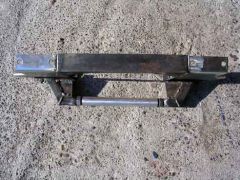
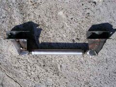
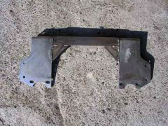
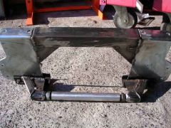
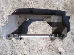
Pretty much done. Here's some pics of how it ended up. The gusseted uprights: The new link all done: Assembled: Top view: 3/4 view: I didn't get the bolt holder done yet, and all of this needs paint. It looks pretty good. Only problem I can see right now is that I didn't tap the tap tube perfectly straight. No biggee, I can just loosen the 4 bolts a bit more and it should still adjust fine. If it's really a bother I can buy a prefabbed turnbuckle from Coleman. This is my biggest fabrication project yet, and I definitely made a bunch of errors during the process. I had fun with it though, and I like what I ended up with. Can't wait to finish my 9000 other projects on this car and test drive the thing... EDIT--One more thing. With the gussets welded in the uprights cannot be dropped without lowering the diff. I don't EVER remember having to remove the uprights without pulling the diff, but FWIW I did lose that ability. -
-
-
-
-
-
How do I remove this nut?
JMortensen replied to PUSHER's topic in Brakes, Wheels, Suspension and Chassis
This thread describes the method I used last time. Worked great. http://forums.hybridz.org/showthread.php?t=92106 -
That is a helluva fish! Are you really into fishing or did you just happen to catch that on the day the magazine guys were on the boat?