AydinZ71
-
Posts
1073 -
Joined
-
Last visited
-
Days Won
27
Content Type
Profiles
Forums
Blogs
Events
Gallery
Downloads
Store
Everything posted by AydinZ71
-
@NewZed *shrug* it’s a lot of money and a ton of fabrication work to net you a tank. I suppose I gave the impression showing-off was a bad thing? OP, do what makes you happy. All my opinions are generally unnecessary ☺️😂
-
My preference is external pump, in every case. Key is to mount the pump either at or slightly below the elevation of your tank/cell. If EFI and NA, a single high-pressure pump in the rear of the car with a regulator at the return end of your fuel rail, is fine. Use the OEM fuel line as a return, and run a new 3/8” hard line from near your pump to near your fuel rail at your firewall. If you want AN fittings throughout, you will need to run a new hard line for the return as well, since OEM is hose barb. 1/4” or 5/16” is fine for a return line. for high power application (turbo, SC), I prefer a low pressure high volume pump in the rear, a surge tank in the engine bay, and a high pressure pump mounted below the surge tank. Regulator return drains into the fuel surge tank, and surge tank overflows back through your tank return line. I think fuel cell is just a flex and overkill for a street car. I just modified my OEM tank to accept a new fitting for a fuel draw line. Up to you. If you are worried about fuel slosh, just install a 1qt surge tank in your engine bay and follow the directions I provided for a high HP application. It’s not sloshing all the time, and the surge tank will solve starvation issues. Much cheaper than a fuel cell for a street car.
-
240z SCCA vintage race car, restoration
AydinZ71 replied to AydinZ71's topic in S30 Series - 240z, 260z, 280z
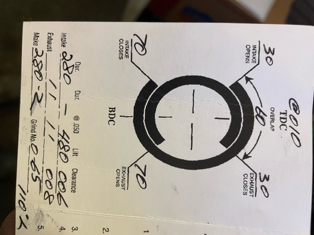
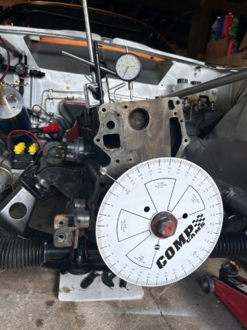
Hi friends! was in Aussie for two weeks vacation and just got back. Ready to get back to work. Head is on the L24, and ready to dial in the cam timing. This is just a mild street head to run while I sort out the commissioning of all the cars components (literally everything is newly installed). I will not swap for the EP head (race cam) until I’m confident enough bugs are worked out on the chassis, clutch, carbs, everything really. first time dialing a cam. Attached is the only document I have on it. I have zero’d the wheel and block through the #1 spark-plug hole and did so over several sweeps to make sure it’s accurate. +.05 to -.05, split the difference on the wheel. Made sure it’s the same + - degree on the wheel so TDC is indeed at the crest. Adjustable cam gear is on, and I believe it’s set to the right teeth. Just ready for adjustment. first time doing this. Anyone know based on the attached image, what degree I should be reading on my wheel when the intake valve is at peak opening? otherwise, I can start measuring degrees at the start and finish of opening and assume the crest is in the middle. the other pic is just my degree where and indicator installed before I put the head on.
-
'82 280zx Turbo max boost without an intercooler
AydinZ71 replied to cpan's topic in S130 Series - 280ZX
@Gollum I think that’s exactly it, thanks for touching on it. It appeared to me to be very difficult to maintain a consistently detonation-free combustion with higher intake manifold temps. The misconception I had before gaining first-hand experience was, I would “hear” detonation. In practice, light detonation was inconsistent and not noticeable when running no IC. The peak temperature experienced in the cylinders would skyrocket unpredictably (obviously more on warmer days), whereby that extra 60 degrees would accelerate the combustion significantly and make it difficult to control with set ignition timing. Combine that with with OEM pistons/rings, and the rings would start seeing significant blow-by after just six months. closed loop feedback with knock detection may be a solution but I can’t say I have enough experience to know for certain. Retarding timing and dumping more fuel when knock is detected could solve it, but without forged pistons or a lower ring landings, there just wasn’t much room for error. So what I’m really saying is, I found it hard to control and over time the rings just wore out. Once an IC was added, the motor became more forgiving. Nissan’s 7.4:1 CR and single digit boost was a very conservative to be certain, and I was pushing that envelope. your other points on heat are well taken. I also agree the total heat (and pressure) in the cylinders does not automatically translate into unreasonable ring wear. It’s really peak temperature, such as from a lean mixture, detonation, or incorrect ignition timing. Naturally, the mechanical affect of knock are there too, which goes beyond simple accelerated wear and can do all the fun catastrophic stuff you mentioned such as cracked pistons, so-on. I guess the old adage is true… it’s all in the tune. -
An open carrier and LSD carrier assembly can not be mistaken for one another. Google “open diff”. They look like four gears arranged in a square, one engaging the other. an LSD carrier will be a cylinder with inspection holes arranged periodically around it. You will not see the same type of gears inside. a Torsen/helical does have gears inside the cylinder, but they look nothing like an open carrier. Google is your friend here, again. the shaft spin test does not work the same way between a Torsen (14’ STI is one) and a clutched unit (OS Giken, 05-07’ STI). The clutch type requires differential torque to overcome the clutch. A helical is the opposite. It requires significant input shaft torque to resist each side from spinning independently. sounds like you may have two Torsen carriers
-
'82 280zx Turbo max boost without an intercooler
AydinZ71 replied to cpan's topic in S130 Series - 280ZX
@Gollum Two identical engines. Same boost, let’s say 10psi. One with an IC, one without. All other variables equal. 100% agree IC engine will make more torque, burn more fuel, and produce more total heat to the engine’s cooling system. You believe the non-IC engine’s rings will wear less than the engine with the IC? Respectfully, I think we will have to agree to disagree. This has not been my experience. -
'82 280zx Turbo max boost without an intercooler
AydinZ71 replied to cpan's topic in S130 Series - 280ZX
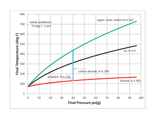
Hmmm… not too sure it’s as simple as a smaller turbo heating the air more than a larger turbo. The efficiency of the turbo for a given flowrate and pressure will have some influence, but nearly all of the temperature rise is purely a thermodynamic phenomenon. See attached graph. Pressure and temperature are inextricably linked. You are correct if you mean putting in more work (for the same pressure and flow) will heat up the air more. I just think it’s small compared to the predictable temperature rise caused by compressing air regardless of efficiency. As for intercoolers, the only reason they did not come stock was to save cost, and the boost was so little that there wasn't enough of a difference in temperature to make it worthwhile. I’m not aware of any mass produced vehicles today with double digit boost that does not include an IC from the factory. It adds efficiency, power (for a given boost), and allows for more ignition advance with less chance of detonation. It’s all upside, and it’s just plumbing and a heat exchanger.
-
IMSA GTU vintage racer build
AydinZ71 replied to clarkspeed's topic in S30 Series - 240z, 260z, 280z
Welcome back Clark! Glad to hear you are on the mend! -
Sounds good John. I’m in.
-
+1 on the stock halfshafts as John mentioned. These things are shockingly resilient. Greg IRA won two national road racing championships with 100% OEM half-shafts. I still don’t quite understand how these U-joints last so long without being serviceable or an obvious means to keep them lubed. in theory, CV’s will gain you back ~2% drivetrain parasitic loss thanks to the “constant velocity” component (why else are they called CV’s), but I’m not aware of anyone who has done a side-by-side dyno test specifically in a Z. Too bad about Fritz getting out of the game. I don’t blame him. It is really, really hard to turn a profit with these low-volume manufactured parts. There really isn’t an inexpensive way to make them in low volume and still have decent quality. T3 and Apex are all the rage thanks to good marketing, but their parts are fairly inexpensive to make. I can find many of their components on McMaster-carr, and the rest is just fabrication, CNC, water jet, etc. not knocking them, just pointing out why it’s so hard to make reasonably priced rotating equipment.
-
240z SCCA vintage race car, restoration
AydinZ71 replied to AydinZ71's topic in S30 Series - 240z, 260z, 280z
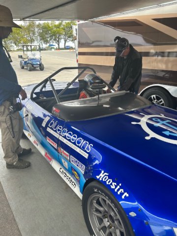
Just a picture
-
Sorry all, trying to follow this thread. Is merc. Purchase still an option?
-
There is a guy out there named Fritz that sells an integrated CV with the shaft ends already machined for STI diff and S30 hub. I bought them a few years ago, but the Z is not yet road worthy (a few more months). Maybe others can chime in. This would save weight, and probably save money if your are going CV’s anyways.
-
240z SCCA vintage race car, restoration
AydinZ71 replied to AydinZ71's topic in S30 Series - 240z, 260z, 280z
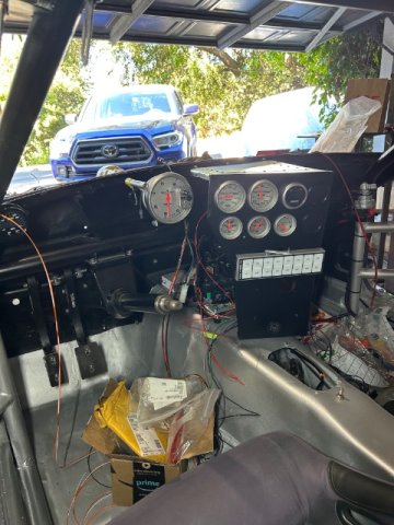
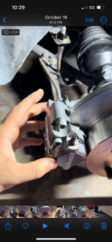
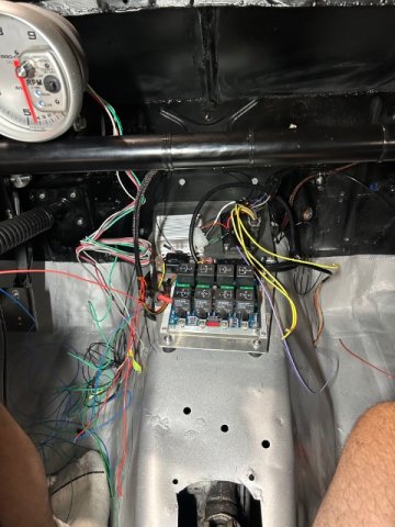
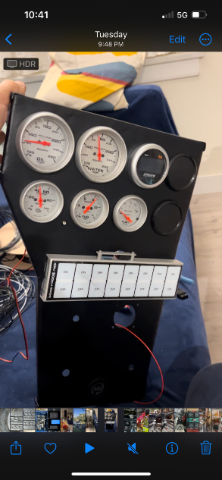
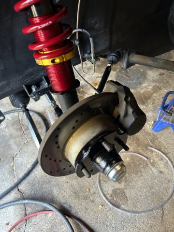
Updates: 1) rear brakes done. many thanks to @clarkspeed for his CAD file! The brackets for my rear dynapro “lightweight”s worked brilliantly. OEM 258mm disk from a 280zx. For those of you that are considering rear disk conversion: think small. You don’t need massive clamping power back there. Unless you are doing it for looks or bragging (which 95% of people are, and is totally OK!), re-consider the added weight of these massive 290+mm disks and four piston rears on a 2300-2800lb S30. You just don’t need them, and are likely to out-brake your front’s. 2) wiring has started about halfway done. Wiring harness to the rear of the car is complete, including fuel gauge, pumps, and rear lights. I have wiring turn signals to get me to-and-from the track until I have the space and money for a trailer. 3) gauge cluster wiring is complete. Going to install the panel and continue wiring. I designed my EDIS+megajolt mini electrical panel to be easily swapped-out with an ECU panel in the future, so I have connectors for the critical sensor inputs.
-
Ok I can help with this. I restored my race car from bare metal over the past three years and learned a lot about paint (did all the work myself), rust, and metalwork. Here are some facts for you. 1) nothing, and I mean nothing, is more critical than adhesion. If you don’t want pieces to chip off when they get struck, you have to focus on adhesion which unfortunately, means attention to detail. 2) no coating will stick better on steel than to an 80-grit (ideally with a DA (dual action) sander) sanded surface. The surface than needs to be wiped with oil/grease remover (very important) prior to applying coating. 3) second-best option for surface prep is an acid wash. Stick to phosphorous acid, as other kinds tend to be too harsh and make adhesion more difficult unless it’s been 100% diluted and removed. 4) remove all rust with a wire wheel until it’s shiny, then scuff with 80-grit. Do not rely on acid to “eat” rust unless it’s literally just surface rust. You will tell if you wet a paper towel with phospho acid and it wipes entirely off. That’s surface rust. Anything deeper needs to be removed mechanically. 5) if removing surface rust with acid, you must while-down the surface with water and a rag multiple times (ideally distilled water) until nothing else domes off. That powdery residue surface you may see is bad. That will get in between your coating and the steel, and prevent adhesion like powdered sugar. 6) read the TDS of your coating. Unless it explicitly says “direct to metal, DTM”, you must apply a quality epoxy over your bare metal first, then spray your urethane over the slowly curing epoxy. DONT wait too long, read the TDS. You don’t want to have to sand the epoxy… very time consuming. unfortunately, if you want a factory-like long-lasting finish, attention to detail is critical. I find rustmort to be too aggressive for me. It will eat your concrete immediately if you spill a few drops (you can see it bubbling). I prefer industrial metal descaler. You can find this at any industrial metal supply shop.
-
240z SCCA vintage race car, restoration
AydinZ71 replied to AydinZ71's topic in S30 Series - 240z, 260z, 280z
Update: ordered all the parts for the rear disk conversion including the willwood dynapro “lightweight” calipers. Many thanks to Clark for his help on the caliper bracket! Painting my Swain coated header and the valve cover. Assembling gauge cluster IMG_1697.mov IMG_1694.mov
-
Silvermine Motorsports -Ford 8.8 Rear End Conversion for 240z
AydinZ71 replied to toolman's topic in Drivetrain
@Invincibleextremes makes a super 8.8 kit out of a mustang GT. He provides upgraded CV axles too. -
240z SCCA vintage race car, restoration
AydinZ71 replied to AydinZ71's topic in S30 Series - 240z, 260z, 280z
@tube80z That's a neat trick Cary! Its definitely something I would try! I was surprised how quickly my front brakes bled, and how few leaks I had. The copper-nickel alloy lines seal so much easier than the experience I had with stainless. I'm a big fan. -
240z SCCA vintage race car, restoration
AydinZ71 replied to AydinZ71's topic in S30 Series - 240z, 260z, 280z
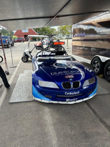
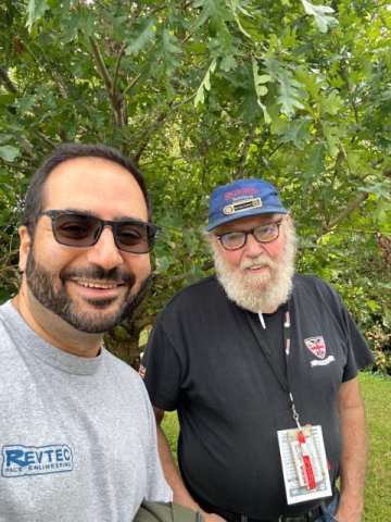
@tube80z hey to you too Cary! @JMortensen yep. Just going to do the disk conversion now, instead of waiting for weigh-in. some shots from Greg’s win at the runoffs yesterday at VIR. Got to spend some time with Sam Neeve and asked a ton of questions. I hope I’m as sharp as he is when I’m his age. young guy by the name of John Hainsworth qualified pole. Made Greg work like hell.
-
240z SCCA vintage race car, restoration
AydinZ71 replied to AydinZ71's topic in S30 Series - 240z, 260z, 280z
@clarkspeed thanks Clark. Because the brake lines and masters were all newly installed, I struggled getting enough “throw” without having the front bleed with the rear. I bled the front first so they had little travel. The front would lock up quick and the balance bar would give me another 3/8” throw on the rear as it pivots. I bet it would be fine if my rear drum cylinder was not clogged, but I seemed to be just compressing air in the rear line. going to get going on the rear drum-rotor conversion w/ the dynalite calipers. Thanks again for all the files you sent a few months ago! Il try to pick a reasonable rotor diameter so balancing with the fronts aren’t a challenge, and I’ll use your calc. -
240z SCCA vintage race car, restoration
AydinZ71 replied to AydinZ71's topic in S30 Series - 240z, 260z, 280z
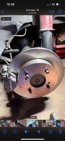
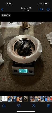
The plan was to weight the car before changing the brakes. Hit a roadblock. One of the two rear brake drums appears to be clogged/seized. Can’t get fluid to come out of the bleed port. The other cylinder is not much better, but it’s got fluid coming out at least. It’s a challenge to bleed brand new brake lines with dual masters, so I have to bleed the front and rear simultaneously. Seems silly to replace the drum cylinder now just to remove them again after j a few months, so it looks like I’ll have to do the rear disk conversion now. @clarkspeed dusting off your really helpful e-mails on the rear brake design and brake setup. I’ll make an initial plan and look forward to your feedback. primary concern now is to ensure I don’t go TOO big in the rear so my brake bias is not too lopsided.
-
Can I replace diff rear cover gasket without dropping the diff?
AydinZ71 replied to kaibiagi's topic in Drivetrain
You can remove the diff cover studs and replace them with bolts. That way, you can replace the gasket in the future without dropping the diff. Only downside is they went with studs for the inherent safety they provide. If the nuts come loose on the stud, the diff doesn’t go anywhere. You will need to be disciplined in torquing the bolts correctly and using loctite if you ditch the studs. A steel bolt threaded into a cast aluminum diff cover is not really risky, but because of the dissimilar metals, they can lose torque over time from vibration and heat cycling on the cover. -
Follow-up from a few months ago. Swain confirmed their coating can, and is often top-coated. I bought some cerakote “glacier gold” and will spray the headers sometime in the coming week when the paint gets here. header is back, but leaving it in the box to keep it clean until I get it painted.
-
Can I replace diff rear cover gasket without dropping the diff?
AydinZ71 replied to kaibiagi's topic in Drivetrain
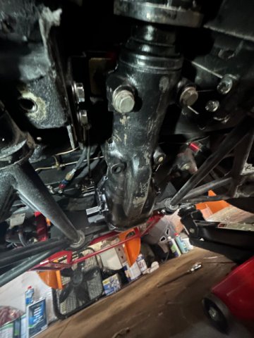
What John said. To be more specific (because I have done this many, many times *headslap*), the mustache bar is in the way. The mustache bar can only be removed by lowering it off the body bolts (which behave like a stud since they hang from the unibody). The diff cover has studs that link it to the mustache bar. The diff and bar are blocked form dropping because of the lower control arm crossmember. So, if you wanted to try and change the rear cover without removing the diff, here is what you would need to do. 1) support the weight of the diff with a jack. 2) remove fastening nut on front diff mount so the diff can pivot 2a) possible need to detach the driveshaft if it keeps the diff from pivoting rearwards 3) remove lower rear control arm crossmember 4) unbolt mustache bar 5) angle the riff downwards when viewing the cover, balancing the diff on the jack and keeping it from falling off the jack. 6) once mustache bar 14mm bolts are cleared, remove mustache bar from diff (M12 studs). 7) remove diff cover. but by then, you basically have demounted the diff for all intents and purposes but its just hanging off the front mount and supported by a jack. Now be careful while you scrape the old gasket material, not to have the diff roll off the jack. -
240z SCCA vintage race car, restoration
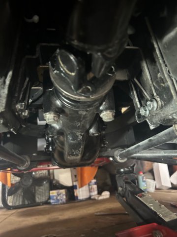
AydinZ71 replied to AydinZ71's topic in S30 Series - 240z, 260z, 280z
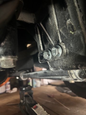
Solved my diff position problem. Moved the RT mount back one notch. Had to trim a bit of OEM steel to make it work, but all good now. Driveshaft fits great and has enough room for play. back to the front wheel bearings and swag bar, then off to electrical.