

RTz
-
Posts
2941 -
Joined
-
Last visited
-
Days Won
23
Content Type
Profiles
Forums
Blogs
Events
Gallery
Downloads
Store
Posts posted by RTz
-
-
Hey everyone, dont buy it from AEM.
it's like 30 bucks here.
Stirring the pot, eh?

I'm not in a position to guess if that count and geometry will work with AEM... maybe someone can confirm/deny.
Also, functionally, its the same as the one I posted previously... punching a .100" hole yourself saves $30. The hardest part of this mod is getting the wheel out. If its anything like the Z32 CAS, you have to drill out the tamper resistant screws, press out the bearings to remove the disk, re-tap, and re-assemble.... If you're capable of that, you're capable of punching the requisite hole, me thinks.
-
Your V8 swap is very impressive for how much you could get while still doing it on the cheap.
Thanks. You'd have to add about $500 or so for the Caprice (wasn't much of a car) and add a bit for cost-of-living... I think that car could still be done under $4k, today.
Do you still have the budget V8 240z?
Nope, long gone. I don't tend to 'sit-still'. One of my abundant character flaws
-
I would think all this talk about freezing water in engine blocks could be fix by running anti-freeze in the cooling system
Exactly.
The manufactures don't give a hoot if you split your block becuase you were too ignorant to use antifreeze. Core plugs are not there for your protection... or theirs.
-
-
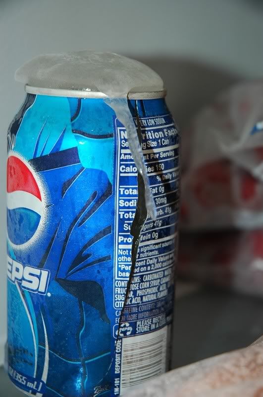
the way water expansion will work, is it will freeze and take the easiest way out...this way is the freeze plug....not cracking iron........
if you drill a safe with a 2 inch hole at the top, fill it to the brim with water, and freeze the safe, the water will expand and dribble out the top, and freeze....the safe wont crack!!!
Doesn't seem to be the case with this Pepsi can... filled with water, top left open for 'the easy way out', and it still split the can...
Clearly a safe would hold out a little longer, but in the end, the same thing will happen... as it will with your engine.
Not specifically picking on you... it just seemed like an easy target
-
I had EXACTLY the same symptoms with my '95 LT1. As it began warming up, one channel of the Optispark would start going erratic, and kill the engine. Let it cool down for a few minutes and start the process all over.
-
Dang!!! I didn't make it Sunday and missed the best HybridZ. Grrrrrr:sad:
If the rumor is true, Dave missed best of show by ONE vote!
-
... and im finally getting around to getting the reamer for him to make a correct rail.
Why does this sound backward?
I sure wish my customers would bring ME the tools I need
-
http://www.rossmachineracing.com/injectortool.html
i found this a couple weeks ago, though about buying one but havent yet, prob wont untill i for sure will need it
That is the tool I own/use. Its a great fit for the manifold side but I prefer it were a little tighter fit for the rail side. I havent had a leak yet... but I'm not interested in making the bet that I never will. On the shopping list is a non-standard reamer for rail machining.
-
I'm sure mine doesn't qualify as 'the best' but it was fun seeing how inexpensively one could be put together. I built one for ~$2600 around 2002... adjust for cost-of-living... http://forums.hybridz.org/showthread.php?t=118146
-
Hats off to you, your car is unbelievable.
I'll second that.
-
Well now the coil issue is resolved
20a fuse for 6 ls1 coils pulling 5a a piece = does not work. hehe.
At 4ms dwell, sequentially triggered coils will only charge individually to 5000rpm. Beyond that, two channels will charge simultaneously. To complicate matters, it won't 'double' as the initial charge current is far greater than at the end of the charge. Moving on... at 5ms, 4000rpm is max. before charging two channels. LS1 coils are going to want around 5ms charge time at torque peak.
... and obviosuly wasted spark would double the amperage..
Yup, but only double below 5000 at 4ms, double below 4000 at 5ms.
Dont know if this will help but my trigger angle btdc is set to 36 I belive anything lower or higher than that number I would have issues with timing.I'm not 'Haltech savvy' so I could easily be mistaken, but this doesn't sound right to me. If that parameter is referencing the mechanical lead before number one TDC, then 36 degrees isn't enough. ECU can't 'go back in time'... there must be as much mechanical lead as the max. timing you run. I run more than 36.
Tommy, if you are having doubt's about your mechanical lead, this implies that you haven't verified that timing is 'as requested'. This will get you into a heap of trouble. You MUST verify ignition timing... after that verify it again
... then verify that cyl. 6 is firing at the same deg. as number one.P.S. Where is your dealer? Is he not helping you sort this?
-
maybe Ron can explain it better...
First, admittedly this is a bit of conflict in interest, so I'll do my best to keep to the facts. That said, If anyone feels this post inappropriate I'll remove it.
Second, and mostly moot... my specialty has been primarily L-series. I use the Nissan CAS exclusively in those applications and have tested to 7500 rpm, with no trigger errors, period. However, as I mentioned previously, I'm opting to read only the 6 slot row.
Third, I've only recently been submersed into the RB installations so specific personal experience is limited. For this reason, I contacted Steve Taylor, owner of Wolf3D, to get a broader scope. In short, Wolf's plug-N-play's use both rows, counting how many slots are within each of the 6, to determine where cylinder one is. The implication is that the actual timing is a function of the 6 slot row. I couldn't say if the strategy (including the unspoken strategy) is any different than AEM. However, I have his assurance that Wolf has proven to be consistently reliable to 10,000 RPM, with a properly functioning, untouched CAS.
Fourth, 'reading between the lines', he defended AEM to some degree, with the statement that these CAS sensors and their wiring are getting old and the *occasional* issue should not be a surprise.
-
Yo, can you get 335/20/13's?
TIA,
-
you know, the saying goes "people see what they want to see"
and i saw a knee. and you saw a...... *starts shaking head*
Touche
-
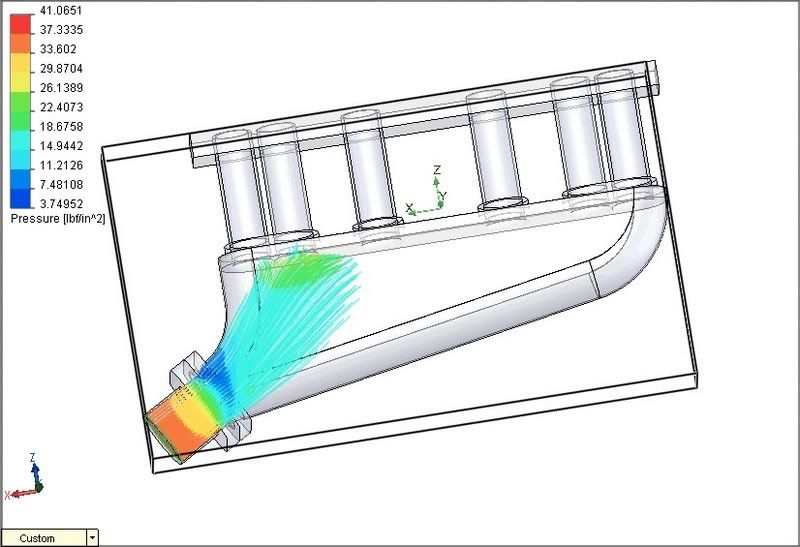
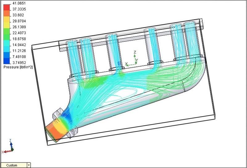
"Turbobluestreak" was kind enough to produce some CFD work on this manifold (Thanks!).
One of the goals of the design was to reduce the turbulence immediately after the TB. Looks like success...
Another high priority was equal cylinder distribution. *Almost* accomplished that. The generous short side radius was an effort to promote this. Seems I still ended up with a small stagnant area in the corner. Also, the unexpected detachment on the outboard perimeter wall seems to cause enough of a low pressure to effect cylinder's 3 & 4 to some degree. The consequences of the reversion in the low pressure zone I suspect to be pretty negligible... the least of my concern's anyhow.....
I found this to be pretty enlightening. However, I must add that static testing like this is a serious over-simplification, completely disregarding Hemholtz, acoustics, valve events, etc... Interesting nonetheless.
In response to this, I've made some plenum revisions and TBS has offered to test them...
-
Blinkers? You don't need no stinking blinkers... hand signals are perfectly legal
-
Great!
Anybody else?
-
Monzter,
I had something similar in mind for manifold number two... with the exception of being two-piece, top and bottom halves. I like your idea much better. Sadly, I'm adjusting the shape of the plenum such that it will no longer work as a one-piece.
I think hand forming .063 over wood will be easy and plenty for prototyping.Keep in mind that we are somewhat past the prototyping phase, as one has already been completed and running. As for .063, I really feel this is a poor choice for boosted app's. I've personally seen ballooned .120" manifolds. I know of BWM folks, running manifold's of similar shape, that have had trouble with .120", hence the internal stiffeners.
I'd be happy to have someone prove me wrong. All I'm saying is, if I were building one with boost in mind, it would not be less than .120" and there would be internal reinforcement.
-
Now that's a marketing GENIUS!
It would have been marketing genius if he would have used a 'woman's knee'
-
I'm not too sure about you guy's anymore... I wasn't going to stare long enough at a 'mans arse' to figure out that it wasn't.
Yup.... still *shaking head*
-
Look again Raff... that's no knee!
"uhhh... wanna trade butt's?... mines gotta crack in it...."
-
I take it there is a show in Canby this weekend?
Yes... http://forums.hybridz.org/showthread.php?p=776495#post776495
-
What do you guys think of the plenum design above.
Picture doesn't come in for me.
By going up to 0.120" I think we will have much less trouble with warpage when welding
That's a fact!
as well as less flexing and cracking when used in boosted applications.
Even at .120", I think internal stiffeners, for big boost applications, would be desirable. Just a few pieces of 1/2" round stock strategically welded in vertically, would probably suffice.


L28 custom intake flange
in Nissan L6 Forum
Posted
Hang tight... we're discussing it.