Zmanco
-
Posts
1568 -
Joined
-
Last visited
-
Days Won
1
Content Type
Profiles
Forums
Blogs
Events
Gallery
Downloads
Store
Everything posted by Zmanco
-
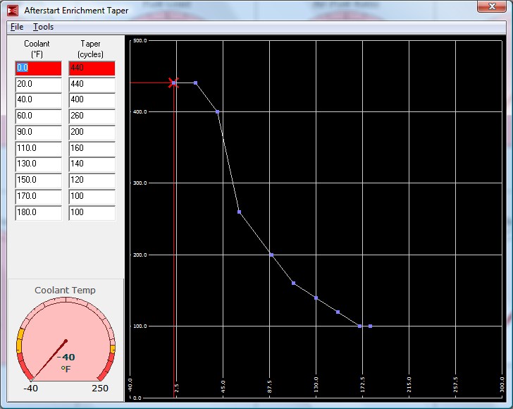
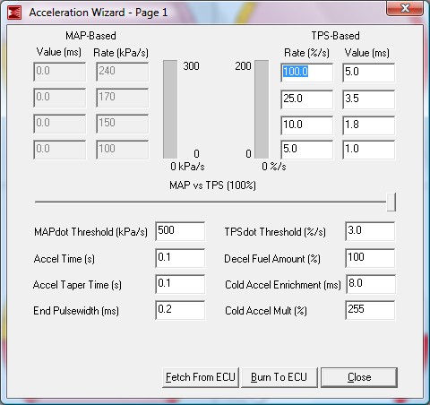
Can you post a datalog along with the msq file? What are the AFR values doing while this is happening? If you don't have enough WUE, then "reving" will become the source of extra fuel due to acceleration enrichment (AE). That might be what's happening here. I'm attaching screen shots of my WUE, ASE, and AE settings. Mine starts and idles from as low as 40F with just a turn of the key so these are reasonably close. Of course, these assume that your VE tables are well-tuned for idle and low-rpm light-throttle.

-
Yasin, your post reminded me to mention that while the event is focused on Zs (all years), owners of Infiniti G35/37, Roadsters, and also 510s are also invited. That leaves you with a hard decision: do you bring the 280ZX Monster? Or perhaps the low-miles Roadster? Either way make sure to use several coats of wax to protect against drool
-
The Z Car Club of Colorado will be hosting the 2009 Midwest Z Fest in Denver on September 10-13. We're still at the early stages of planning, but we're going to have a variety of events including: - Track event at the new High Plains Raceway - Shine and Show - Mountain Drives (possibly to include a car museum) - Awards Banquet We've set up a site at www.midwestzfest.com where you'll be able to keep abreast as things firm up. In the next few weeks we'll have a hotel selected and will be able to provide specifics on the schedule and costs. In the mean time, if you ever thought about visiting Colorado, here's a great reason to do it this year.
-
 When I did the conversion I tried the stock 14" steel spare and an older Enkei mesh wheel and neither fit. I sold the spare on ebay and bought a can of fix-a-flat and saved nearly 50 lbs of dead weight.
 -
No, I'm afraid not. If each injector is fired separately, then you need to wire each one with its own 6 ohm resistor.
-
I'm afraid I have no experience with RB motors so can't help you with how the injectors are set up. But for the two examples you list (and assuming the injectors are typical low impedance), for all 6 fired simultaneously using a single resistor, it should be 1 ohm. Note, this resistor would need to be wired between the +12V source and the injectors and not between the injectors and the FI controller. I say this because it's unlikely that all 6 will be switched by a single circuit. For the opposite with each injector fired independently, each should have a 6 ohm resistor. FWIW, I doubt all 6 fire as a single batch. Unless the injectors are rather small, there's enough time in a cycle, even at 7k rpm, to fire 2 banks of 3 each, and electrically (from a load and noise point of view), that is more desirable as well. BTW, nice find of the 2 ohm 25w resistors. How much do those cost? They look easier to mount.
-
Let's go back to basics for a minute: Why are the resistors needed? Answer: the injectors are basically a big solenoid. One of the characteristics of a solenoid is that when power is first applied, it has a very low resistance and then as the current ramps up, the effective resistance rises which in turn reduces the current. In other words, there's an initial surge that levels off. The resistors are required for low impedance injectors to limit the initial surge to protect the transistors that do the switching in the FI controller (such as megasquirt). There is no magic exact value that is best. There is a tradeoff between limiting the current and slowing down the time it takes for the injector to open. This really should be measured for a given injector because beyond a given level, allowing a larger initial current (smaller resistor) won't cause the injector to open any faster but will put a larger load on the switching transistors. Read this thread if you're interested in how this can be measured: http://forums.hybridz.org/showthread.php?t=121843 The point of all of this discussion is that as long as you're in the ballpark with resistor values there's very little to be gained worrying about tweaking them further.
-
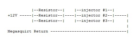
In practical terms, it makes no difference if you use 6.2 or 6.8 ohm resistors. You will never be able to measure any meaningful difference in performance of the engine. You might be able to measure some very slight differences in opening times for the injector, but that time is programmable in Megasquirt so you can just adjust it if you have the tools to measure it that accurately. But since you're curious about the theory, let's discuss it. - Let's assume you're going to wire the 6 injectors into 2 banks of 3 each. This is the typical way to use megasquirt on an L6. - Each bank will be wired independent of the other. That means that we want one resistor pack in series with 3 injectors that are wired in parallel with each other. See my very crude illustration attached. For 3 typical low impedance injectors wired in parallel, the target value of the Resistor Pack is 2 ohms. Ideally we'd like to just buy a 2 ohm resistor with a rating of 25W. In fact these aren't readily available so we'll make a pack ourselves by using several resistors wired in parallel. Note: from a purely electrical point of view, you could also wire a single 6 ohm resistor in series with each injector to achieve the same thing. But since Megasquirt is structured to support only 2 injector circuits (banks), we'll continue to model 2 Resistor Packs. The math is R(total) = 1/(1/R1 + 1/R2 + ...). 10W is a typical power rating for inexpensive wire wound resistors, so if we use 3 in parallel, we have 30W of dissipation capacity. Let's make the math easier by assuming that all the resistors have the same resistance. R(total) = 1/(1/R1 + 1/R1 + 1/R1). Simplifying yields R(total) = (1/3)R1 So using 6.2 ohm resistors produces a pack with resistance = 2.1 ohms 6.8 ohm resistors produce a pack with 2.3 ohms. As I said up front, the difference between 2.1 and 2.3 ohms in this application is insignificant to the operation of the injectors. Does that help? Note: I watched a PBS Nova special on Fractals last night so I'm feeling rather academic today Hope this was at least somewhat useful.
-
Did you see my post #39? You can buy the same resistors from mouser.com for $1.09 instead of $2.99.
-
That's true, but I've found that ignoring those datapoints can cause anomalies at light throttle portions of the map. For example, it will continue to recommend much higher VE values at the lower left corner of the map every time it's run. For the coarse tuning I turned AE off. Now that I have more experience with the tools, I leave it on and instead use my own common sense "override" on MLV's recommendations before accepting them. The fact is that a good VE table tune will result in rather small AE values. But if you start with larger AE values and tune with it on, the VE table will be tuned "around" that. As was suggested earlier, as a noobie getting started and still learning how the tools work, it's best to turn AE off while tuning.
-
Just remembered that you're using MSII/Extra. There is a pretty active beta trial going on right now for 2.1.0 that has made some very significant improvements in fuel delivery and I expect the next beta release will handle EGO much better. I only bring this up because 2.1.0 calculates fuel differently than 2.0.1 did, meaning that I had to retune the VE table. If you're going to stay with MSII/Extra, you might want to load the latest beta dated Jan 2, 2009 to avoid having to retune your VE tables. It's the best/most drivable release I've seen yet and I'm told the fuel calculations are not going to change going from beta to released code. That way you'll only have to tune once And if you decide to add an Idle Air Control valve, the 2.1.0 beta release is nearly as good as a modern OEM tune. Again, I only bring this up since you said this was going to be your daily driver. Obviously, first you have to get it to idle http://www.msextra.com/viewforum.php?f=91&sid=291b80c14ef381a7b4e4a6a6793b24dc
-
I agree with the previous comments about turning AE and EGO off for tuning. However, it's quite likely, especially if the engine is cold (<40F) that you will have to get some significant ASE (After Start Enrichment) going in order to get it to continue to run after the initial crank/start. Don't be afraid to use 50% or more at 40F. The number of cycles should be in the several hundred range which will equate to several seconds depending on how high the engine revs. Another things to watch for when you do get the O2 sensor: you can destroy one by running very rich for extended periods. The only fix will be to replace the sensor itself. It won't happen in minutes, but if you run for extended periods, it can happen. It happened to me, and I found a lot of others on the Innovate Motorsports forums who had similar problems. Another benefit of a wideband O2 sensor is using Megalogviewer to do the tuning. Basically once you get the tune "roughed in" enough so you can drive, use Megatune to capture a datalog while driving. Vary the engine range and load as much as possible. Then park the car and use MLV to analyze the datalog. It will recommend changes to the VE table. It's not very helpful for idle or very light throttle cruising, but for the rest, especially for WOT, it works pretty well. If you have the O2 sensor far from the engine like I do (mounted AFTER the collector of the 6:1 header) you will eventually want to use MLV with a multipass approach to dealing with the varying delay based on RPM and Load. But don't worry about that now - that's for another time when you're fine tuning. BTW, I only bring this up because you said this was going to be a daily driver - I wouldn't worry about it for a track-oriented tune.
-
How did you mount these under the dash? And is there a baffle behind the speaker?
-
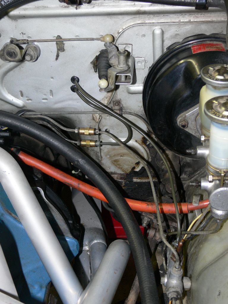
Tips for installing brake bias valve?
Zmanco replied to heavy85's topic in Brakes, Wheels, Suspension and Chassis
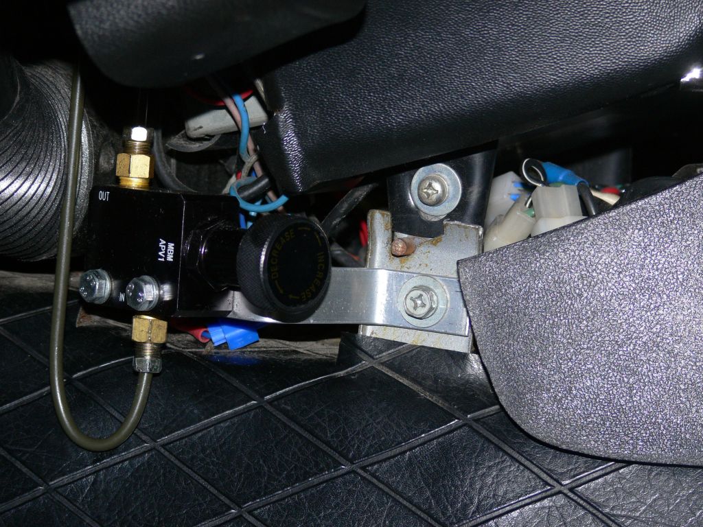
One time when I had the intake manifold off I mounted the prop valve under the dash as part of a "while I'm at it" project. The bracket is just some aluminum bar from Lowes that I bent using the bench vise. First I formed the tubing for the "under dash" part leaving the part for the engine compartment straight. That was then inserted through the two holes I drilled in the firewall. The intake manifold on the L6 needs to be off for the tubing to have a place to go until you can route it to the distribution block. I don't know about clearance for a V8. Originally I had the prop valve mounted on the front fender inside the engine compartment, but it was a hassle to fine tune it on track days. Plus, as the day progressed I found that the optimum setting changed. Obviously it's easier if the valve is accessible inside the cabin. Also, while I don't usually drive the car in the rain, now and then I get caught out unexpectedly and on those drives I turn the valve out 1/2 turn to be sure that I'm not doing pirouettes on public streets. To Jon's point, I could have done this with the valve in the engine compartment, but it's a lot easier to do without having to pull over and raise the hood, especially when raining. Edit 1: I had originally wanted to mount it the way cygnusx1 did, but like you, didn't want to pull the tranny. When I converted to FI and had the intake manifold off, this was the easier path. Edit 2: Like most "while I'm at it" projects, this one took a lot more time than the pictures suggest. Finding the metric unions here in CO was a pain, and let's just say that the brake lines in the pictures weren't the first ones I tried
-
The MSA piping still needed tweaking to get it to fit properly. In the end, I would have been better off taking it to a custom muffler shop to build from scratch.
-
The stock S30 exhaust systems were just fine for a stock motor and did not significantly reduce power. I'm not sure what crappy emission control setup you're referring to on the S30 exhaust manifolds? From what I've read and experienced myself, the stock exhaust manifolds do a very good job and only become a limiting factor when you begin to modify the head/cam setup. Back to the original question, I have the MSA header (6:1) with their 2.5" exhaust and dynomax muffler. It was a bit loud in a good way with the stock cam and quieted down a lot when I upgraded the cam. At this point now I've had it on the car for about 3 years and quite a few track days and the baffling in the muffler is loose. When it gets warm at idle, it sounds like I have a bad muffler bearing Also, the sound from the driver's seat with window down is rather raspy at WOT as the revs go from 3.5k to 6.5k. I can only imagine how it sounds from behind the car. This spring I'll probably replace it with a flowmaster as I really don't want to attract attention with all the racket when driving on the street. Also, when listening to the videos on youtube, keep in mind that the placement of the camcorder makes a big difference in the tone. Notice how much deeper the sound becomes when the camcorder is placed on the ground vs. even a foot or two up in the air. I wouldn't put a lot of stock in the sound from the videos - much better to hear one in person if you can arrange it.
-
Interesting that you solved the issue by removing the MSD 6A. I run with one too (6AL, but basically the same box). I very much doubt changing where you switched the power would make a difference. In a closed system such as a car, that really only matters for devices that have very small signals, such as O2 sensors. I've been thinking of removing mine as well. I originally installed it when I ran triple webers and thought the multiple spark would help at idle and also liked the idea of a protective rev limiter to prevent damage if I missed a shift at the track. But with MS I get a rev limiter and I don't think multiple spark really made any difference. And getting rid of the box (and the noisy tach converter) would probably improve reliability as well. Hmmmm....
-
Before you go too far tearing into the engine, there's a simpler thing to check. If the carb that feeds the 3 "dead" cylinders ran too rich for a while, it may have fouled the spark plugs and with the stock ignition, it may not be getting enough spark to ignite the fuel. Pull the plugs and see if they're covered in soot. If so, get some new plugs and verify you can start the engine. Then tune the carbs (discussed many times on this site) before you foul the plugs again. If this solves the problem, you might want to check that the plug wires are ok, and replace the points as well (or better yet, upgrade to electronic ignition). A weak spark will make this more likely to occur again.
-
Not exactly. In this case the output of the alternator (closer to 14V when the engine is running) is across the resistor and injectors combined because they are wired in series. Some of that 14V is dropped across the resistors, and the balance across the injectors. The total resistance is the sum of the resistor pack plus the combined resistance of the injectors. If they are wired 3 per bank, then their combined resistance is 1/3 that of a single unit. If they're wired 6 per bank, then it's 1/6.
-
When I installed MS i wired the injectors into 2 banks of 3 each (each with its own set of wires back to MS) and configured MS so that each is fired separately. I added the resistors later and it was easier to add 2 packs of resistors (1 for each bank) than to add 1 pack for both. You can use 1 pack of 2 ohms for both banks, but only if you wire it between the injectors and the +12V source on the relay board (or however you're supplying +12V to the injectors). If you want to fire all 6 injectors as a single batch, then you would want the resistor pack to have a resistance of ~1 ohm. If you're installing from scratch, I'd advise against this approach as you're switching twice as much current and hence causing twice as much noise (actually it's 4 times as much energy since power in this case is a function of the square of current). I'm not saying you need to rewire if you've already done it this way and all is working well, just saying it's a better approach to handle them separately since MS already has that capability.) Another potential issue with firing all 6 at one time is that it causes larger pressure pulses in the fuel supply, but I really don't know at what point this becomes significant. I'm running NA with the ZX turbo injectors (265 cc/min) and can't notice any difference firing all 6 in a single batch. Larger injectors would cause larger pulses and at some point could exceed the ability of the fuel supply (piping and pump behind it) to keep up and the pressure would drop. It might be overkill, but I figured wiring 2 banks of 3 each minimized this issue so I wouldn't have to worry about it.
-
One more thing, these resistors have solid wire leads (not stranded) so it's important to mount them so that the wire leads don't move around and eventually fatigue and break. I mounted everything on a piece of masonite under the passenger seat and used zip ties to hold them to the board.
-
I ordered 6 pieces of 6.2 ohm 10W resistors from Mouser. I wired 3 in parallel for each bank of injectors creating an effective resistor of 2 ohms 30W. The Mouser part number is 280-CR25-6.2-RC and they cost $1.09 each a year ago. If you assume a worst-case resistance of 1 ohm for the injector + 2 ohms for the resistors, then you have roughly 4 amps current. That equates to ~30 watts being dissipated by the resistors IF the injectors had a 100% duty cycle. Of course they don't and the injectors are closer to 2 ohms, so you might be able to go with smaller resistors (say 5W), but I wouldn't do it as the resistors will run hotter and could cause issues with where you mount them in terms of heat dissipation. The key is you want to get to ~2 ohms resistance with ~25W capacity.
-
I believe it does support EDIS. Here's a screen shot of one of the ignition setup pages. FYI, I'm not trying to convince you to go the Extra code, just suggesting you should look at it since it appears to have more emphasis on IAC. That plus the larger tables was what originally convinced me to switch. Keep in mind that it is a branch off the main code base and hence there are less developers working on it. But I've been on it since early last summer and have been quite happy with it. Here's the main forum for Extra: http://www.msextra.com/index.php
-
You might want to look at the MSII/Extra code. The "pre-beta" 2.1.0 code has significant improvements to the IAC code and he (Ken) should be releasing a new version any day now. FWIW, I'm running with a Bosch 3 wire IAC valve and am very happy with it. I had wanted to go the route you took, but couldn't find one cheap, and then found the Bosch on ebay for about $20. There are a lot of other nice features in the Extra code as well.
-
No problem Nigel, just wanted to make sure you weren't headed in the wrong direction with your tuning strategy. Dave, I've noticed the lean condition at start when the engine is warm and your explanation of warm fuel in the rail makes sense. With the MSII/extra code there's pretty fine grain control of ASE so I give it about 5 seconds (assuming an idle of 850 rpm) of +10% which seems to help.