MONZTER
-
Posts
821 -
Joined
-
Last visited
-
Days Won
22
Content Type
Profiles
Forums
Blogs
Events
Gallery
Downloads
Store
Everything posted by MONZTER
-
That sounds great Tony. I'll get with you to check them out. It will be good to see if there is any magic in those old HKS intakes. BTW my computer fried the other day, so I have been recovering all of my files (nothing lost) and my new computer will be in soon. This is why there have been no updates lately. Back on real soon. Jeff
-

L6 squish discussion... (the battle against detonation)
MONZTER replied to OlderThanMe's topic in Nissan L6 Forum
Yes, the angled plugs are all part of the master plan. First a few more details. Like I said above the head of the pistons will be a mirror image of the head. What I did not say was that the shape of the piston under the intake valve will be domed, and the shape under the exhaust valve will be dished. The idea is to use the domed portion under the intake to make some squish which will force the charge to the exhaust side, right where it needs to be to flow out. The angled plug will now be closer the true center of the mixture, just like you said. You just have to imagine the chambers are no longer traditionally shaped, they will now be offset towards the exhaust valve. So, a few things that will make this work. First all of the chambers are designed in 3-d on Pro-Engineer, so it will be easy to design the piston tops to be exactly a match to what I am trying to do. Second, since the chambers are all CNC machined at one time, they will be perfect in shape, size, and volume to perfectly match the CNC’d piston heads. I am hoping the small tight chambers from the above idea will make for a very fast burning set-up, which means less detonation, and less timing. All good things. Check out the link I posted above, It goes into much more detail BTW The head above (P90) is just roughed out. Once the head is surfaced, and all of the valve guides and seat installed, it will be put back in the CNC machine and cut to its final depth with a much finer step-over -
L6 squish discussion... (the battle against detonation)
MONZTER replied to OlderThanMe's topic in Nissan L6 Forum
OTM, Have you ever seen the heads I modified? Here is what I currently run a N-42 welded for max quench with 36cc chambers. On a 1mm over 240 lower end with flat tops .015 out the deck with a comp gasket. Runs great on 91 octane all day Here is a picture of my next head (P-90), not finished yet. I took it to the next level with welding up the chambers, ports, and plug holes. Made a CAD model for the CNC to cut them out all the same. High quench, lots of swirl. I will be doing as 1 fast Z states, in the fact the piston will mirror the head. I will be using this on my 280 turbo project. -
L6 squish discussion... (the battle against detonation)
MONZTER replied to OlderThanMe's topic in Nissan L6 Forum
Maybe some have you have read this http://www.theoldone.com/articles/The_Soft_Head_1999/ Good overview -
Moving Rear Wheels Back?
MONZTER replied to JustinOlson's topic in Brakes, Wheels, Suspension and Chassis
The AZC rear control arms used to be this way. At least a few years ago. I was told you had to run the style of camber plates like John C sells that dont require welding. After you installed the arms you would have to line up the camber plates as if you were tying to add more caster as in the front. This should eliminate the binding, because both top and bottom are now moved back. -
Have you seen this one? FP3582HTA Turbo http://store.forcedperformance.net/merchant2/merchant.mvc?Screen=PROD&Store_Code=FP&Product_Code=NTFP3582HTA Not cheap but, it is supposed to spool better than a standard 35r
-
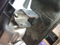
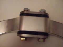
Hi Justin, The plate is .250. Punching 4130 that thick will work but the coined edges are not so pretty. For high volume production that would be the ticket. So what do you guys think about the urethane bushings? are they going to hold up, and do you think the set-up will be too stiff and noisy? I have a urethane filled stock mount now, and the gearbox rattles around pretty good at idle with cam I use. I could always put some rubber ones in there for the street?
-
Good Question - To bend up the bracket accurately (I'm a freak about that sort of stuff) I would have had to either laser cut or CNC the blank out of 4130 plate. Well a lot charge at the Laser Company is $175.00. And I only planned on making 1. Now the time to set up the bending, and screw a few up getting the spring back just right as well as the compensation of bend = lots of time and money, again for 1 pc. Now after bending it would have to be fixture and drilled for the cross bolt that pass through the bushings = more time. CNC is easy to set up, and can run unattended unlike a bender or all the driving around to the different shops. So long story short more material cost, but less overall labor time. Again for 1 pc. Now production I agree 100% with you, hence why the part looks like it does, because it was designed for production bending. Oh ya, and my friend own the CNC shop :-P:-P
-
Yep, aka 240sx 5 speed conversion
-
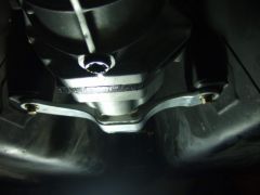
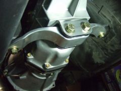
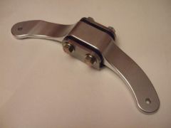
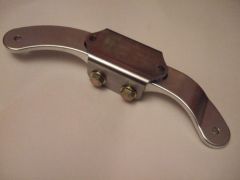
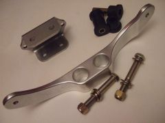
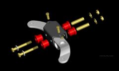
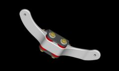
Hey All, I just finished up making my new transmission mount for the 71c swap. I'm pretty pleased with the results, so I thought I would share some pictures. It looks like It is going to be plenty strong, and the new design for the urethane bushing should keep the trans pretty tight. Another benefit is the improved exhaust clearance. I will be running 3.5 inch tubing from the turbo back, not the pipe tucks way up above the floor, which is pretty tough to do on a 240 with its narrow tunnel. So here are the specs: 71c trans Engine moved back 3/4 of an inch just so the valve cover fits past the hood catch -(the 71c mounts sit about 1 inch further back and the engine is now 3/4 back so a total of 1.75 setback on the mount) You can see the bowed shape of the cross member to allow mounting in the factory screw holes. 6061 T-6 CNC machined cross member 4140 Chrome-moly steel CNC machined trans mount bracket Urethane bushings from 73 up cross member 1/2-20 grade 8 hardware. I think I will anodize the cross member black and powder coat the trans bracket black as well (nothing too flashy on my car) Here are some pics of the CAD models as well as the finished parts. Click on the pics for a larger view from my picture gallery. Thanks Jeff I like the way it tucks up behind the tranny case
-
-
-
-
-
-
-
-
-
-
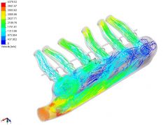
Already finished moving the diverter forward to the middle. Looks like it will stop the vortex from going counter-clockwise, and help it flow more linear. Good idea Jeff
-
All right. the answers are in. Looks like an improvement in reducing 2 of the 3 vortices. The flow looks to be more even through the runners. The flow diverters seem to better even up the distribution of air. The bumps in the top seemed helped runners 2-6 with the vortices, but the first bump seem to be helping create the vortex in runner 1. So anybody want to post some sketches on there ideas to help get this thing perfect? Here are the results: Some new videos: http://album.hybridz.org/data/500/velocity_test9a_rev4.avi http://album.hybridz.org/data/500/velocity_test9b_rev4.avi http://album.hybridz.org/data/500/velocity_test9c_rev4.avi Thanks again for everybody's help. Jeff
-
-
-
-