-
Posts
818 -
Joined
-
Last visited
-
Days Won
17
Content Type
Profiles
Forums
Blogs
Events
Gallery
Downloads
Store
Everything posted by MONZTER
-
For just the reason stated by Zguy36 above. I thought a bigger taper in the bottom would help even out the flow in the second half of the core and eliminate any dead spots. I knew what direction the air was flowing so I figured a little more room on top would keep the velocity more consistent. I think most intercoolers are symmetrical because they are universal fit and you can then run the air in any direction you want.
-
Yep I am getting some turbulence in the dead spot where the first and second halves of the core are separated. I will post a close up of that section so you can see it better soon. It’s not perfect, but as you said a lot better than what it was, and I will have to be just happy with that. I actually have plans to make my own tanks from scratch for my next build, and they will eliminate this problem, I just wanted to salvage the intercooler I already bought. I bought it in the first place because I am getting tired of my car never being finished, and I thought I would save some time by having one built. Well after getting it I couldn’t just leave well enough alone.
-
The software is Cosmos Floworks, I think it’s at its limits with the narrow fluid space in the core. The company I work for just bought CD-Adaptco Star CCM+ and Star Pro-E for our external flow models, seems much more capable as it is the same software used by the F-1 teams. I will re-do some of these test with the new software after I get some training. http://www.cd-adapco.com/products/STAR-CCM_plus/index.html
-
It seems like there has been alot of talk about the pluses and minuses of the different intercooler configurations for our Z cars. Which is better? Same side inlet and outlet, or opposite side? That’s for another post that has been debated over and over. What I wanted to show was my decision, and what I have found out, and how I have modified it to make what I think is a good solution to an efficient design. My decision was to go with the inlet and outlet on the same side, as I really wanted the shortest possible tubing, not to mention what I believe to be a intercooler with less pressure drop. 
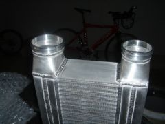
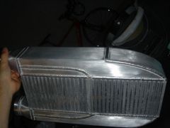
So I ordered up a Custom sheet metal tank Spearco unit 18x6x3.5 , only to be really disappointed when it showed up, as I have seen better looking agriculture equipment. The inlet and outlet were just butt welded on with no regard to smooth airflow, and the ends were cut nearly square, again not really smooth creative work. Here is a pictures of the stock unit as delivered from Spearco. 
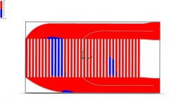
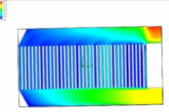
We have all heard talk of how this type of intercooler recycles the air inside, in a circular motion near the inlet and outlet. Also, it is known as not being very efficient to cooling, because all the air gets pushed to the end of the tank, not letting the air flow evenly through the core. So I modeled it up in Pro-E and set to work doing some CFD flow testing on it for a little look. The test was done very simply, ambient on the inlet side and 25" on the outlet side. I wanted to test total CFM flow as well as pressure drop and distribution of the air. Please keep in mind this is only a quick test and the core is correct in dimensions, but obviously no tubulators, So look at the info for what it is, a comparison between one test and another, not between this test and a actual unit. 
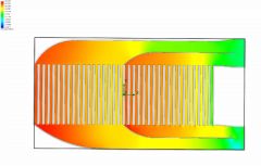
So you can see in this picture first off is a recirculation effect. The air enters in the bottom inlet, up through the core, out, back down the core, back up the core... click to enlarge the picture and look at the flow arrows. Next is the pressure plot- 
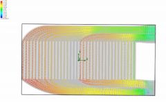
Finally the velocity plot. So now on to the modifications. 
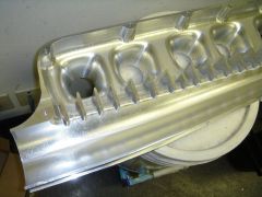
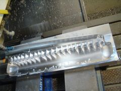
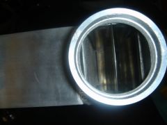
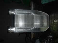
First off is the inlet and outlet. I made nice square to round transitions 2.5" inlet and 3" outlet. No longer is there a sharp square edge right before the outlet, you can see the effect on the pressure plot above. 
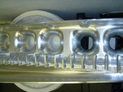
Next, I made smoother tapering sections at the end of the plenum. 
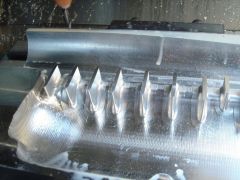
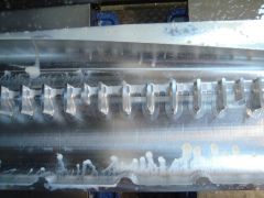
Finally, I made divider plates to basically split the Plenum into two halves, hopefully improving the balance of flow, fixing the recirculation problem, increasing the heat rejection and thus efficiency. 
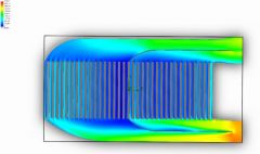
Check out the arrows - no more recirculation Pressure plot shows the air is being distributed more evenly through the full core, not just he ends. The smooth inlet and outlet also show the lack of a high pressure flow reducing area right before the outlet. Check out the velocity. The air seems to stay more consistent in speed, I assume this is why there is a little more pressure drop. 
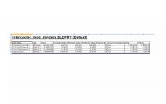
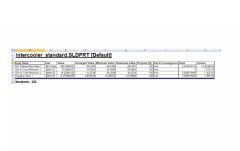
Check out the numbers. An increase of 162CFM through the same core. So what do you think? Does it look like it all makes sense? Jeff
-
Intake mani porting...too much for a newb?
MONZTER replied to Calgary280ZT's topic in Nissan L6 Forum
If you know someone who can weld aluminum, cut it open and go to town. It is really easy to clean them up once you can get inside. -
Sorry, I forgot to answer you on this one. The machine in the picture is a Fadal VMC 4020 with Fanuc controls. He does al of his programming in MasterCam 9 This machine is about a year old. They just got a new 6030 in the shop for larger projects. Total of about 5 vertical machines in the shop right now. So you want the file? Hmm I'll have to think about that one:icon42:
-
The first CNC pictures from before were of the roughing operation The final pass has been finished on the inside and it is ready for the back details. I had him spend a little extra time with a smaller step-over on the diverter section, but leave the entry into the runners a little more rough. I figured I would have to do some smoothing on the runner entries after welding on the Wiggins flanges anyway. He has already roughed out the inside of the front half. Should be only a couple more days to have it all finished machined. After machining I will pin it together for alignment, add a little tape to seal it off and bring it to be flow tested before welding it together for good. It seems like you guys like seeing the progress of the CNC work so I guess I'll keep posting pictures
-
So, picked up some finished components from the CNC shop today. Here is what’s new- click on the picture for a bigger view The cover plates for the integrated vacuum and AIC rails. As you can see in the model I have designed rails in the back of the plenum. The cover plates will go over the slots and be welded close to form a rail. The top one is for the AIC solenoid and PCV valve. The bottom one will be for the MAP, blow off, fuel pressure, and boost gauge. Since I am using ITB I wanted a signal from each runner to collect into the rails. I also got the weld-on connectors for the Wiggins clamps. One side of the adapter will weld onto the plenum, and one side will weld to the ITB. The Wiggins clamp holds them together with no tools, so it will be easy to pull off the plenum to sync the ITB’s (thanks Tim for the idea) The bad news is the other day my friend at the machine shop called and said “hey your flanges are finished� What I said, and he sent me a picture. By mistake, he ran my old files of the bolt on adapters I was going to use to connect the plenum to the ITB's OOps. So he pulled up the correct files and finished the Wiggins adapters above. So, anybody need some beautifully machined adapters? They are standard Webber spacing and 45mm ID 6061. PM me and I can send you prints of them. 6pcs total. Since they are 1 off custom parts there not cheap, but I am just looking to help out my friend get some of his cost back. Jeff