MONZTER
-
Posts
824 -
Joined
-
Last visited
-
Days Won
25
Content Type
Profiles
Forums
Blogs
Events
Gallery
Downloads
Store
Everything posted by MONZTER
-
Thanks Paul, I got the 8mm stainless studs a long time ago when ARP started doing the import stuff. Somewhere ARP found me stainless 10mm 12 point nuts, but they had no matching Stainless studs. I have to use 10mm studs for the top of the intake flange, as I have angled the runners up relative to the head and bolts will not fit in the holes without hitting the runners (does that make any sense?) Oh well I have ugly black oxide studs I will be stuck with for now. Thanks again for looking. Best Regards Jeff
-
Hi Paul, Do you know if ARP now makes 10mm studs and 12pt nuts that would fit the FI intake. I also tapped the head on the outside exhaust flange for 10mm so I would need six if you could get them. Thanks Jeff Exhaust/Intake studs Stainless steel 170,000 PSI Tensile strength exhaust/intake studs, M8x1.25 thread… Studs utilize internal hex for inserting the studs, 170,000 PSI tensile, and come with 12 point nuts. Come in packs of 4, 8, 10, and 12. Come in lengths of 32mm(1.25â€), 38mm (1.5â€), 45mm(1.75â€), 51mm(2.00â€), 57mm(2.25â€) 4pack; 32mm 400-8001 38mm 400-8002 45mm 400-8003 51mm 400-8004 57mm 400-8005 8 pack; 32mm 400-8011 38mm 400-8012 45mm 400-8013 51mm 400-8014 57mm 400-8015 10 pack; 32mm 400-8021 38mm 400-8022 45mm 400-8023 (OE length Datsun L-6) 51mm 400-8024 57mm 400-8025 12 pack; 32mm 400-8031 38mm 400-8032 45mm 400-8033 51mm 400-8034 57mm 400-8035 Hope that helps, Paul
-
Rainer, Ignore the initial advance number, that is for start-up only. Just look at the numbers on the chart. Also, please remember what Ron said, every configuration and every car will be different. Please use the chart as a reference only. Best regards Jeff
-
Hi Rainer, Those are my actual timing numbers per RPM and MAP points. The head has small 36cc chambers so the burn is very fast. A few degrees is probably need to be added for a stock N-42 head
-
Thanks for the help. Good point about the fuel cut on a turbo engine Jeff
-
Hey Tec 3 people. I never have got my rev limiter to be "soft" It seem to come on very aggressive and really jerk the car hard when it hits. I have it set to 8000, so I am worried about the sudden hit shaking the drive train to bits. For tunng, I have set the rev limit to 3000 to try and get a soft limit while street driving, but have had no luck. It seems like the different setting don't do too much. Do any of you guys have a good set-up you would like to share the parameters with me and the group. Thanks Jeff
-
Maybe this thread will help. Some of us posted our Tec 3 tables. My car is also a L-24, but my head is pretty modified so my timing might seem a little less than most. http://forums.hybridz.org/showthread.php?t=122406 Best Regards Jeff
-

70 240 -next upgrade rear sway bar?
MONZTER replied to 24ounce's topic in Brakes, Wheels, Suspension and Chassis
When I had 225-50-16 v700 all the way around, I used 1 inch up front and 3/4 rear mount Addco style in back, felt great for me. When I switched to 245 45-16 all the way around the car went from what I like to way more oversteer. I tried no bar in the back, but the car felt kinda slow to respond to input, I even tried more rear toe / no good. I next tried a 1-1/8 front with the 3/4 rear bar again, still not feeling good. Finally, I made a new rear bar out of 5/8 stress proof and put the 1" back in front and the car is back on track to what I like. -
Hi David, Been running my tank set-up for over 1 year now. I have been autocrossing it as well as daily driving it. I can say I have never had a single problem with fuel starvation. I can run below a 1/4 tank for autocross and not a problem. I will use this same set-up for my turbo motor I am building with no worries. Jeff
-
Arizona ZCar Stainless Steel Valves - Help...
MONZTER replied to naviathan's topic in Nissan L6 Forum
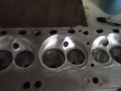
I just had a head done by Dave Rebello. I sent him OS 46mm intake and OS 38mm exhaust, as well as stock size Intake and stock size exhaust, all were SS swirl polished undercut. I also sent him oversized seats. When he was done with it he ended up using the OS valve seats, the stock size intake, and machined the OS exhaust down to be only 1mm bigger than stock. He said he does not like the OS valves from his testing. So my head when finished flowed 212 at 25" .5 lift on the intake and 150 at 25" .5 lift on the exhaust. Note: this head was a p-90 for my turbo project and the valves were the SI brand. BTW from what I can tell everybody is using the SI valves and just re-selling them. You can buy the SS swirl polished, undercut ones diretly from them for about $8.00 each and they ship really fast. Nice parts. here is their link http://www.sivalves.com/ocforeign_valvessp_nis.html Hope this helps Jeff -
New Design Front Arm
MONZTER replied to Mike Mileski's topic in Brakes, Wheels, Suspension and Chassis
Looks like it should be perfectly aligned now, good idea -
Vacuum source for Turbo Map Sensor w tripple throttle bodies
MONZTER replied to MONZTER's topic in Turbo / Supercharger
Thanks for the help guys, your comments got my brain working again, I figured out what I am going to do. Best Regards Jeff -
Vacuum source for Turbo Map Sensor w tripple throttle bodies
MONZTER replied to MONZTER's topic in Turbo / Supercharger
Thanks Tony, So you think the integrated log in the cannon manifold is not good enough.. huh..( I think the ID is .5") , I should add a second log... Is this to isolate the log equally from any particular runner? Thanks again Jeff -
What is your guys opinion on the best source for a vacuum signal on a triple throttle body turbo set up. I need a good signal for MAP, Fuel pressure regulator, Boost gauge and Blow off Valve. I was thinking about using the Cannon Manifold that has the tube connecting all the runners, and then tapping into only the last runner closest to the firewall. Do you think I will get a good clean signal, or will it be biased too much to the last cylinder? I want to be as clean looking as possible without a bunch of hoses running everywhere, like if I used all 6 of the fittings in the throttle bodies and made a separate vacuum log. Thanks for your opinions Jeff

-
Some people said they were saving them. How do you do that? I cant figure it out, does youtube let you do it. Thanks Jeff
-
Help, Dissasembly of KA transmission not going well....
MONZTER replied to Sparky's topic in Drivetrain
just finshed doing mine. Also have to remove the shifting insert form the side of the case (2 10mm screw heads), and push out the pin on the shifter rod at the shifter cover plate. Here is the fische for that trans. http://carfiche.com/fiche009/s13/?3:a:10 -
I saw this somewhere It looked like it was just thrown together HAHAH
-
My Understanding is that MSA is getting them from a special source in Japan. Before they were NLA in the US I got mine from MSA for 130.00. I assume there getting ripped on the price, and then mark it up there standard amount, thus the final high price. I guess it all supply and demand, and people gota make a living.
-
-
-
-
-
-
-