MONZTER
-
Posts
828 -
Joined
-
Last visited
-
Days Won
28
Content Type
Profiles
Forums
Blogs
Events
Gallery
Downloads
Store
Everything posted by MONZTER
-
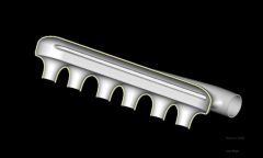
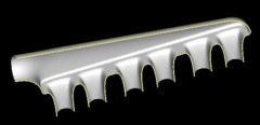
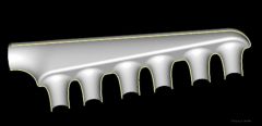
Similar to what I had planned, but I was going to tack weld it together for testing on a flow bench, and then weld it up when happy with the results. You can see inthe cut away all the extra material I left in the slot area so it can be made wider if it needed to be. I am trying to figure out how to measure the pressure loss problem with out the software??
-
Thanks for the link Dave, good reading. Very depressing reading actually. I do not have access to the CFD, so it sounds like it would be impossible to get the right configuration with out the software. My design so far is just based on what I have seen and read. I have very little to no experience in fluid dynamics, and I would hate to build this manifold to have it be worse than a simple open plenum design. HMMM what to do, risk it and make one - possible wasting the time and money, or go with what we know and make something like a plenum used on the RB motors. I hate problems like this when my hands are tied by my limited resources. Making it is the easy part for me. I don't think common sense will work on this project. Thanks Jeff
-
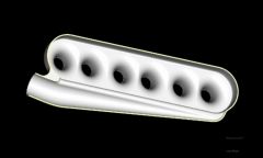
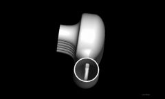
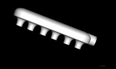
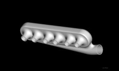
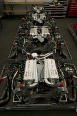
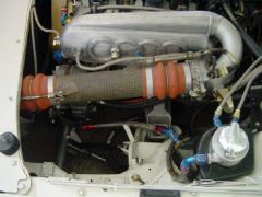
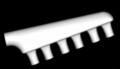
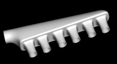
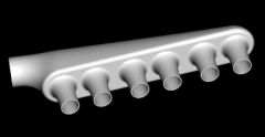
I started a thread a few days ago regarding the shape of air horns for the new intake plenum I am working on for my Turbo L-28. Here is a link http://forums.hybridz.org/showthread.php?t=127653 So I have begun to develop the shape and design of the plenum itself. Been doing a bunch of reading on this forum as well other sites. Seems like everybody is trying to do the same thing, get the air as smoothly and evenly into each intake runner. Ron Tyler made a nice looking manifold, but determined there was room for improvement. I have also heard Tony D talk about the internal baffles on the Japanese plenums used back in the day. This is where I began my design. Luckily, no one ever re-invents the wheel and I found exactly what I was looking for on some 80's Audi rally cars. Check the link http://www.bufkinengineering.com/intake%20manifolds.htm and pics below: Here is also a link to some stuff BMW was doing (big Volume boxes) http://e30m3performance.com/tech_articles/engine-tech/airbox_symposium/page5.htm So you can see in the pictures of the Audis, they are putting the air into a sub-chamber that then lets the air enter the main plenum evenly the entire length it. This will eliminate the action of the air passing the first few ports and favoring the back ports. I think this is more of a problem on turbo applications as opposed to NA. So I designed a plenum with the same concept as above with the following specs. -Plenum volume (without the sub plenum and air horns = 5853cc -The area of the 3-inch sub plenum tube where it enters the bottom is 45.6cm -The area of the slot between the two chambers is a little bigger at 57.4cm. Extra material is designed into the slot area to allow enlarging or changing the shape after testing. Here are some pics of the concept so far: In this cross section you can see the slot connecting the two chambers- this view kinda looks like the inside of a turbo when looking down the outlet- You can see the clean entry into each runner- And the cross section of the chambers- I saw in Ron Tylers design that someone on this forum did a CFD analysis of his design. I can provide any type of 3-D file of this idea if anybody is interested in doing some CFD work on it and seeing how it looks. So I am looking for comments suggestions or simply holes blown in this concept. Thanks Jeff
-

-
-
-
-
-
-
-
-
-
-
Devcon - Not on the intakes, I'll weld before that, but to fill the port floors in with the raised intake ports yes. Its actually Manley 2 part epoxy material specifically for the job (probably made by Devcon) TWM also used to make thin CNC throttles like only 20mm wide, but I had these already and one set of injectors far back were already there.
-
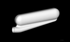
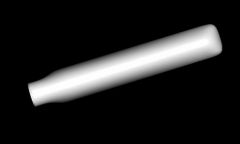
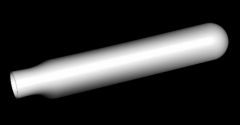
So I modeled up a quick plenum to see how the shape of the horn would interact with the shape of the plenum. The shape is no where final, just to show the ideas. I am thinking the square ones are looking smoother and more streamlined (less flat bottom) What are you guys thoughts? I just started doing research into the plenum shape and volume. Do you guys have any link suggestions for good reading on the subject? I have read all I can find on the forum here. Good stuff Thanks Jeff
-
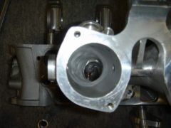
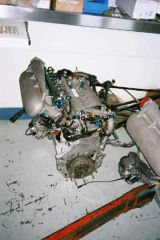
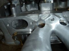
Tim was correct, The throttles were made from pieces starting with a set of TWM 46mm bodies and intake. The flange was cut off the intake runners and then the runners were seperated and machined at 20 degrees to improve the entry of the runner into the head as well as increase the distance from the header to the bottom of the bodies (less heat). I made the flanges to be 4 bolt instead of 6 bolt for the purpose of adding a second set of injectors in the flanges pointing right at the back of the valves. The parts were all welded up and then smoother out to look like cast again. I added a bunch of material to the inside radius of the runners to smooth them out as well as giving more material to straighten out the inside of the runner. The path is much straighter than it looks from the outside. The flange mounted injector bosses are not welded in yet, they will be smoother in as well. Here are some pics of the process. Sorry if there are too many pictures. Jeff
-
-
-
-
-
-
-
-
-