MONZTER
-
Posts
828 -
Joined
-
Last visited
-
Days Won
28
Content Type
Profiles
Forums
Blogs
Events
Gallery
Downloads
Store
Everything posted by MONZTER
-

Strengthening Front Anti Sway Bar Mounts
MONZTER replied to 260DET's topic in Brakes, Wheels, Suspension and Chassis
The brakes on my car are AP aluminum 4 piston post mount in front with 13" AP cross drilled rotors. I designed the rotor hat and mounting bracket for the post mount setup myself. Everything is CNC machined from 7075 and hard anodized. I only made 1 set. The backs are AP 2 piston post mount (same as a lotus Elise front) The rear rotors are cross drilled Z-32 rotors and the backing plate is also custom designed to bolt on and use all of the parking brake hardware from the Z-32. Again only 1 set. Thanks Jeff -
Thanks for the replies, I just did not know if I broke some un-said golden rule or not. I did pay for the work and I do own the head. Dave never even hinted at "Don’t show this or hide this" Like I said, he was super nice, prompt, professional, and on time. I just did not want to “burn any bridges†if there was some un-said rule I broke, I would defiantly like to use him again. Thanks Jeff
-
Do you really think that was bad of me to post those pics? I dont want to piss anyone off, Dave seems like a great guy, and I did not realize that he might not want that sort of thing shown. I'm feeling kinda stupid now:bonk:
-
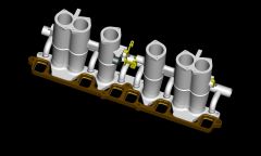
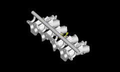
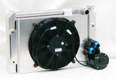
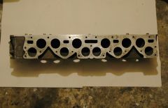
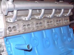
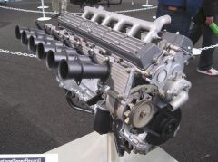
I cut in half a bunch of heads lately to investigate various ideas. One idea is just what you mentioned. Directly above each exhaust port is a nice open area that you could pull the water out from. I believe the water first has to flow past all 6 pistons before moving up and across the head for #5 and #6. I am thinking about using a radiator bulkhead mounted water pump with 2 outlets. One outlet would go to the current front cover/front of the block. The second outlet would go around the block to the block drain lug under #6 so cooled water is going to the back as well as the front. Now if you tapped into the head above the exhaust ports and let the water flow out, it would eliminate the water having to pass over so many areas. Some of the problems I see are that you would have to block off the head bypass since the water is now being pushed instead of pulled. you will also have to block off the water pump opening. You would also have to plumb only cylinders #2-#6 leaving #1 as the current thermostat housing where the other 5 would collect and then go back to the radiator. #1 and the thermo housing is also a high point in the system so trapped air should not be a problem. Here are some pics of the water pump, old nissan designs, as well as a manifold design I am working on
-
-
-
-
-
-
-
It's a P-90
-
IMS - Industrial Metal supply in Irvine
-
Hi Braap, Why on the intake only? That’s the only way I found them. I got them from the Kameari guys in Japan, and that was the only way they sold them. I did not know where else to get them except by going custom. Maybe some other application would have fit, but I had no clue where to find this info. I was thinking it was because of a durability thing with the exhaust valve? and the hardness of the seat material? - just a guess. The head was done by Rebello. Dave got the head flow 212 at 25" .5 lift intake and 150 at 25" .5 exhaust. He said he spent way more time on the exhaust than the intakes. I'm hoping it will run pretty good. Jeff
-
-
For me I think the biggest improvement isn't totally from the manifold, but by going stand alone fuel injection with a MAP based system opposed to a MAF system. This is what let me get rid of all the extra stuff and make the HP increase.
-
Hey Tim, Got some Oversized Beryllium seats from Kameari directly. They are supposed to help transfer the heat better. Just had them installed, but not run em yet. I also got the Beryllium guides to help again to pull the heat out of the valves. Not cheap stuff, but I figured good insurance.

-
Nice MFI runners, Thats cool. ever run across any pics of the Lucas flat slides on a Z. Oh waite stop dreaming this is about a stock intake:bonk:] Whats all those wire and hoses, just pull it all off, we did...
-
What about the one MSA Sells? I think there was a discussion not too long ago about this single groove damper.
-
Hey Braap, Makes sense about the cooling, so why would anybody want to close them off at any level? I know they talk about it in the "how to modify book" Is it because of the extra windage? or maybe the high RPM loss of oil in the rod bearings? Hmmm Thanks Jeff
-
So, on a L-28 turbo build with 1973 240 rods, should I close off the oil squirter hole in the rod or leave it open??? Does anybody know what the pros and cons are?? Thanks Jeff
-
Strengthening Front Anti Sway Bar Mounts
MONZTER replied to 260DET's topic in Brakes, Wheels, Suspension and Chassis
John, Thanks, Good solution cutting off the threads on the old tie rods and building them into the new ones. I really like all the interesting ways people find to do the same thing so many different ways on this forum. Great option for people without access to a lathe; where did you find the swaged tubes? I remember seeing them once somewhere, but could never find them again. What is the wall thickness and material spec for those tubes? Thanks Jeff -
Strengthening Front Anti Sway Bar Mounts
MONZTER replied to 260DET's topic in Brakes, Wheels, Suspension and Chassis
Yes I know what you mean about the bar hitting the tie rod. Keeping the bar close to the frame rails helps with this, but your idea for a different tie rod is perfect. I built some straight tie rods from 4340 with heim joints on the end to adjust for bump steer, as well as give more clearance on lowered cars. Have not tried them yet. The tricky part about making the tie rods was the fact that one of the inner tie rods uses an m14x1.5 left hand thread. I found that if you call McMaster Carr they can custom make any tap you want for a reasonable price. -
check this link http://aircraftspruce.com/menus/ha/fittings.html aircraft spruce
-
Strengthening Front Anti Sway Bar Mounts
MONZTER replied to 260DET's topic in Brakes, Wheels, Suspension and Chassis
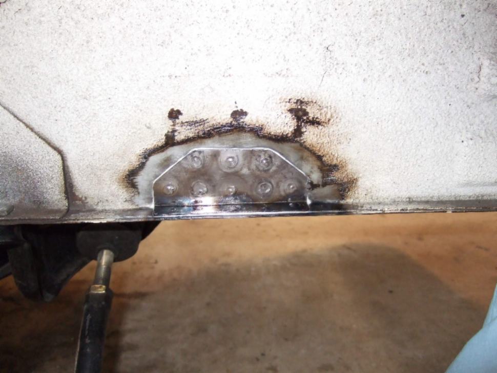
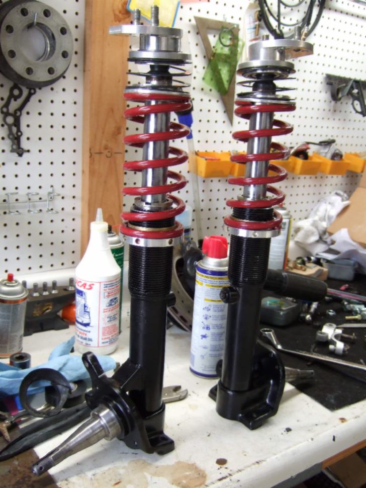
Here is how I fixed my setup. Same problem with the mounts cracking, as I have been using heim joints on the ends and solid aluminum with 20% glass filled Teflon bushings for the pillow blocks. I wanted to keep a factory look to it so I made the gusset plate similar to the existing gusset on the cross member pick up. I rosette welded it on and through the bottom of the rail. The good part for me was no burned up paint in the engine compartment as it is covered by the frame rails. I saw mentioned earlier about mounting the sway bar end links to the strut, this is how I have mine. Two reasons why I did this. First I could use a longer end link, minimizing the movement of the link, and lessening the chance of binding, and second, by mounting the link on top I could put the bar down closer to the control arm, improving the angle of the bar. I was looking for the bar to be flat when under braking. John, do you remember that article a while back in Race Car Engineering, where they talk about the rate of the bar changing as it rotates and the angle of the end link moves from perpendicular relative to the bar? They suggested that this could be an advantage. Has you read this article? Seems like most of the new cars are done this way, any disadvantages? Here are some pics.
-
I have read that completely removing the guide bosses can actually hurt flow. The idea was to thin them out, as thin as the guide, and then give them a leading and trailing edge to enhance the flow around the guides. They are also directed them with the shape of the port to enhance swirl. I have also heard that the trailing edge rib remove the possibility of the air expanding behind the guide and slowing down the flow, as well as the wet flow of the head being improved. This is all just what I have read, so we won’t know until I finish the port work and flow test it, then run it. Braap, do you have anything to add about your experiences with the shaping of the guide bosses