MONZTER
-
Posts
828 -
Joined
-
Last visited
-
Days Won
28
Content Type
Profiles
Forums
Blogs
Events
Gallery
Downloads
Store
Everything posted by MONZTER
-
-
-
-
-
Hey Tim, Who did your ceramic coating, and which process was it. Thanks Jeff
-
I don't know if this the correct way to start tuning, but I am self taught and this works for me. 1.) I set my VE Table to Zero and then put in what UAP and POT Wintec recommends based on the tuning wizard 2.) I set my Correction factor to something stupid like 50% (I am using a wideband connected tot the Tec unit) 3.) I start the car and immediately go to the VE table correction and start tweaking the table in the appropriate cell to get it to idle until warmed up 4.) after I get it warmed up I continue to tweak the VE table until it is idling where I want it to be ( for me 14.64) 5.) Next shut the car down and switch the VE table over to the Fuel Table (Corrected Injector Pulsewidth (ms) 6.) I look and write the numbers (Offset FPW) in the MAP and RPM zone I was idling in, and then look and write down the numbers (Offset FPW) where I believe my max RPM and MAP will be. 7.) I go back to the VE table and re-zero out the entire table 8.) I once again go back to the fuel table and look at the changed numbers 9.) I now adjust my UAP and POT settings on the top of the page up and down until I get the cells back to the numbers I wrote down before I re-zeroed my VE table 10.) I re-start the car and it idles pretty good with little correction 11.) I do some wide open pulls in third gear and once again tweak the VE table until it is where I want it running 12.) shut down the car and repeat steps 5 through 9 focusing this time on my max RPM and MAP cells 13.) re-start the car and it is really close on the idle and WOT 14.) Turn the correction factor way down to like 10 and get my accell and other enrichment parameters configured 15.) Go for a drive with the autotune on and let it dial in the VE table 16.) change the VE table to a graph and smooth it out 17.) Car runs pretty darn good Again this is my method, and I have no idea if it is correct or way harder than it should be, It just works for me. I think it would be great to hear anyone else's methods Jeff
-
Hey Rags, I did not mean you were wrong, just wanted you to know that the two were tied together. I just did not want to see you spending money on dyno time to get the TOG perfectly dialed in, only to find out it needs to be changed after modifying the IOT to get it to idle. I did my initial tuning on the street with the correction factor set at 50%. Once I got my TOG and IOT within 5% correction, I went to the dyno to tune the VE table. Even after the VE tune on the dyno I found some more power from data logging and doing an auto tune function, and then smoothing it out on the graph. I posted some of my tables on this link. http://forums.hybridz.org/showthread.php?t=122406 Good Luck Jeff
-
I don’t think that’s quite correct, as the TOG and the IOT work together. If you dial in the TOG and then change the IOT the curve will move down or up requiring you to modify the TOG again. It is a balancing act to get the car to idle correctly and do a full throttle pull. Once you get this worked out it time for the VE correction. I recommend lots of reading: Check out this manual http://www.directignition.com/pdf_files/tec3r.pdf look at pages 61 down it has a good explanation of what you are trying to do. Here is another good source of info http://www.thenewspaper.com/auto/info/tecfaq.htm it is about the Tec II, but still really the same. It is in a forum format so it is a little more real world.
-

Strengthening Front Anti Sway Bar Mounts
MONZTER replied to 260DET's topic in Brakes, Wheels, Suspension and Chassis
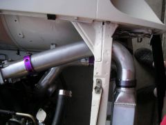
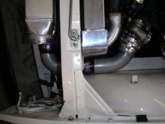
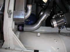
Wow, thanks for the comments, much appreciated. I have not finished the front dif mount yet. I am waiting to finish my 3" exhaust routing, and then will build the mount around that. I think somebody else around hear built a mount using the mounting holes for the diff strap. Looks like a good idea, I will probably do something like that. Jeff -
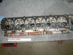
Tim, I can cut up more of the head, but it looks as if the "flash web" runs the length of it. I would say it is a casting error. You can really see the difference in the quality of the casting between a N-42 and the P-90. On the outside near the port openings a N-42 is very nice and smooth. On a P-90 that same area is very inconsistent and rough. I wonder if this reflects on the inside. Tony D, it looks like you could access some of the flash through some of the openings in the gasket surface, and also by removing the plugs in the rocker valley. Sorry I cant cut up the N-42, its in great shape and going to be used on one of my projects. I did compare the water ports on the P-90 and the N-42 and they were the same. I think it was the E-31 that was different. Jeff
-
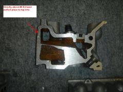
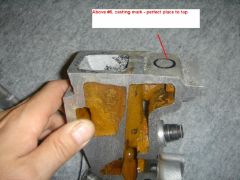
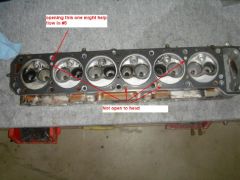
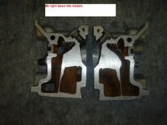
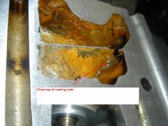
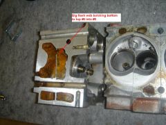
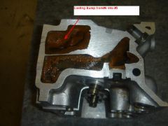
Hey Guys, Here are the pics of the cut-up P-90 showing the inside water passages. The first two pictures show the inlet points in the gasket surface. You will notice that there are holes in the head that are blocked off by the HKS steel gasket. These could flow water if the gasket was opened up. In the second picture you will see holes in the head gasket that do not have holes going into the head. This makes me wonder if this was for a reason, or just a manufacturing convenience, so that 1 head gasket design would fit many application of the different years. I wonder if an improvement could be had by opening the gasket up to the holes in the head, and the head up to the gasket. Hmmm. The other pictures show a large casting flash rib blocking probably 50% of the water passage from the bottom of the head to the top. This web was going from the #6 to the #5 cylinder. It appears that these flash webs are through the whole head. There are also some large casting bumps from the exhaust studs that would appear to restrict flow. The final pics show the nice open cavity that flows above the exhaust ports. We talked about taping into the head above the exhaust ports, this looks like an ideal place. Sorry about the big pics, but wanted to show the details. Click the pics to enlarge them from my gallery Enjoy, Jeff
-
-
-
-
-
-
-
-
-
I was waiting for someone to bring this up, Tony the trouble maker HAHAH. Now there is even more to think about...
-
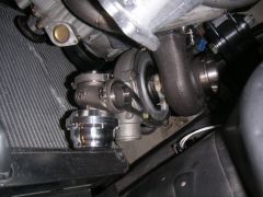
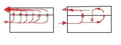
the radiator is made by a company called Meziere http://www.meziere.com/index.php?pgName=rad Interesting idea about tapping only one of the cylinders above the exhaust port Tim. I will take some pictures tomorrow of a cross sectioned head at #5. Have you ever noticed that the cooling inlet size and hole positions on the head where it mates to the block has changed over the years. Some holes have been added and some omitted as well as there size. It would be interesting to check the differences between your N-42 and a P-90. I have both of those heads at work, I will check it out as well, maybe Nissan found the same thing out when they went to the P-90 head from the N-42. I was also thinking about the flow. You know how they say on an intercooler with the inlet and the outlet on the same side causes a recirculation of the air inside the intercooler, and that baffling helps this. I wonder if the water could be seeing this same type of effect. Here is a really bad illustration of what I am talking about. On the left is what it should probably work like and on the left is a possibility of what could be happening? Now if we only had a clear plastic head and block to watch the water flow:
-
-
New Design Front Arm
MONZTER replied to Mike Mileski's topic in Brakes, Wheels, Suspension and Chassis
I have a set of AZC front arms, and they did indeed bind when topped out. This was 5 years ago and I think there design has changed. I ended up cutting off the straight front tube, and adding a bent one to fix the angle. I then decided just to build my own. -
New Design Front Arm
MONZTER replied to Mike Mileski's topic in Brakes, Wheels, Suspension and Chassis
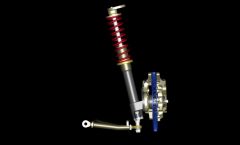
When the car is on a jack and the front struts are fully extended, are you worried about the tie rod/ball joint binding? It looks like the center of the joint is perpendicular to the centerline of the arm. I wonder if the joint has as much rotation as the stock ball joint. Hopefully it's all good. Looks real nice, and easy to adjust. I had to put a small bend in the front tube on mine so that the heim joint was in the middle of its range at ride height. This made it so no binding under full extension or compression. You can see the bend and angle in the front view on the picture below: -