MONZTER
-
Posts
826 -
Joined
-
Last visited
-
Days Won
27
Content Type
Profiles
Forums
Blogs
Events
Gallery
Downloads
Store
Everything posted by MONZTER
-
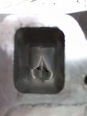
This is the inside of the intake and some pics of the welded N-42, and the build
-
Hi Jon, No I don’t take any of this personal. There is always room to question such discussions, I enjoy it When I first built the engine I Dynoed it to have it roughed in. And then spent time breaking it in and then lots of street tuning. at that time it made 210 at the wheels. There have been changes to the intake and exhaust since then. Here is the Dyno plot from then. This time it was a different Dyno, different operator. You could be right that its wrong, but this is just what I got from them. One at 210 when first built and not fully tuned and 231.5 now. I personally do not know if this Dyno stuff is legit or not, and actually I don’t care if my car made less, I just know it runs pretty good for what it is Good discussion
-
The cam is the 270/280 stage 3. I feel many people overcam our nissan engines and bleed off too much dynamic compression. Dynamic compression is what I feel is the trick to getting a pump gas friendly moter with higher compression (along with quench) to have a nice linear power curve. Compression sounds about correct. 1mm over sized with flat tops sticking out .015, 1mm head gasket. maybe a touch more CR than that No CFD on the current intake, just some guess work. It has a bad zone about 3000 that I have to lean out and retard the timing a bit (less fuel burns quicker)
-
sick
-
Yep, thats it. Don't want any steam pockets in the head with the higher compression and pump gas max power was at 7000 and still going. I have the rev limiter set to 8000. Because it was on their dime they did not want to blow anything up, so they shut it down at 7000. I think it had more. I will post the charts when we can upload pictures again.
-
Correct, the intake was cut up and the plenum enlarged, the runners externally welded and straightened, as well as the throttle body being relocated. Oh ya 6 bolt flanges so it will bolt to an early head here is it roughed out
-
A old friend of mine called me last week and said "Hey do you still mess with those old Z cars" I said "Yes, why do you ask" He goes on to tell me that he has a friend who works for some studio and does the sound clips for video games. Hey tells me that they are looking for a old straight 6 Z. I get the guys number, call him, and sure enough its true, he can’t tell me what studio, or what video game he is working on (secret stuff I guess) but after seeing a video of my car tells me he will pay me (yes pay me) $350.00 to hook my car up to a Dyno and record it. So I say OK. Today I met the guys doing the recording, it was really cool. They took a bunch of sound clips of various things about the car. For example, opening and closing the door, the hood, the hatch. Putting the keys in the ignition, and pulling up on the parking brake, ect. He even did a sound clip of the rally clock I have in there. When it was my turn, they hooked the car to the dyno and had microphones all over the engine and behind the car in various places. The operator / tuner took over and did some quick sound test / runs to check the car out. He said it was running lean over 4500, so proceeded to jump on my laptop and start tweaking my VE table for the Tec 3. He did a few more runs and got my AFR down a bit to 13.8 from about 14.5. They went on then to record the car starting, stopping, revving, and at a bunch of different RPM ranges. So when it was all done he handed me the dyno sheet. My car made 231.5 HP at the rear wheels and 195.9 lbft of torque. Not bad for a 240 engine running pump gas, I think. I will post the charts later as there is some issues with the site that won’t let me upload pictures. So my car is still NA (no I have not finished my turbo build yet) Stock 240 block 1mm over with factory flat top cat pistons, balanced and shot peened rods, balanced crank. Head is rather special as it is a N-42 with welded chambers to add quench and bring them down to 36cc with stainless swirl polished valves and my own port job (no idea what it flows) The cam is a MSA split duration. The intake is something custom I built out of a stock intake, and it is fuel injected with 320cc injectors all controlled by a Tec 3r. So the new score equals 231.5 HP at the wheels 195.9 torque free dyno tuning session My cars sound in a video game $350 bucks in my pocket not a bad way to spend a Sunday. Here are some pics of my car Thanks MONZTER
-
I ran the head again without the plenum, and it was 219 CFM at .5" lift 25" this was with a radius inlet on the intake port flange. At 28" it ran 136 CFM. I totally agree with you, except I think how you do it is not old fashioned. The computer stuff is just a tool I like to use to identify problems and spark ideas. It is by no means the end all be all. I believe it is simply a good first step in the process that includes flow bench testing and dyno time.
-
I just re-ran the intake and head last night with the new software. The flow came out to 200 CFM at .5 valve lift 25" I believe the 220 number was just the head alone and with the other software. I could run it just like you asked. any particular valve lift or special requirements. what type of velocity stack? just simulate a clay radius donut around the port?
-
Yes this is how the software works. I can apply a Mass flow to the inlet with a pressure outlet, or I can apply a depression to the outlet and see the CFM rating. Most of what I have been doing is to apply 25" on the outlet with a stagnation inlet. This is how I ran my plenum. I would apply 25" to each runner outlet and let the air flow. I tweaked the design until all ran very close to the same. After I got this dialed in I then ran it with 735 CFM on the inlet and measured the flow out of each runner. A while ago a talked to Kevin at accurate injection. He gave me some insight of what a ITB flows on his bench. I modeled it in the computer and then ran the simulation. I remember them being very close. When I run the plenum and port set-up above the computer says they are running about 220 cfm at 25"
-
Ya that make sence. This is what I did, the guide supports are only as wide as the guides, but smmoth out the front and back of the guide to make them more streamlined. You can see this in the Cad model in this view you can see how clean the flow around the guide boss is
-
here are some more pics, close up on the valve head area. click on the picture for the super huge view. I also uploaded some more video, but Youtube really destroys the quality:icon13: enjoy
-
-

-
-
-
Here is the link to the scan of the article http://www.savefile.com/files/1998523
-
Here is a really good article on heads, that I found very clear and to the point. Give it a read and I can look into making some more pictures to better explain what I am trying to acomplish. ( I cant get it to upload any ideas? its 12 mb .zip file)
-
Dynamic results would be great, but I am still thinking about the proper simulation, and what would be the set-up. So say an engine is spinning 7000 RPM. the cam is at half speed so each valve opens about 58 times per second. How different would this dynamic situation be vs testing them all open at 1 time. Also, consider there would be no shock wave being created so the results would still be so so. In the modeler program (which we don’t have) you can actually dynamically open and close the valves, and then apply a moving mesh in the solver. We have an 16 processor cluster we run on, but I think this would even hurt it. What are your thoughts?
-
I have never used Fluent, but this is defiantly not pick it up on your own software like Floworks. I had a 1 week in house training (40 hrs) and still I am just scratching the surface of what it can do. It is defiantly geared towards full time, degreed in fluid dynamics, operators. You really have to know the physics. Good thing is the customer support is phenomenal. We are assigned a full time, always the same person Support Engineer who is really good and helps answer any question. He even helped set up our first case. CD Adapco www.cd-adapco.com Good company to work with.
-
Yep
-
Hi TBS, Yes, it does have the ability for a movable mesh, I could also apply a velocity to a specific boundry. I am currently working on a time table to phase the cam opening and closing. This software can even do combustion, but thats waaaay advanced
-
-
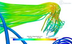
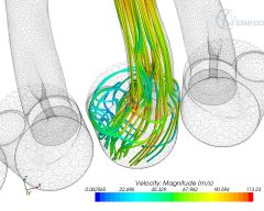
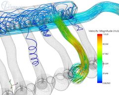
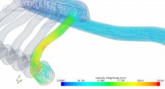
So a little back on topic... I have been using my new CFD software called Star CCM+. It is a really high end code, used in everything from military to F-1 - super powerful. So along with my intake; I have been working for a while now on redesigning my combustion chambers and ports in a P-90 head. The idea is to take all the new ideas being used today to increase the performance and detonation resistance in my motor (if I ever get it back from the machine shop) Basic idea is to maximize quench, swirl, and burn area. 1.) the new shape has 2 quench pads, one in the standard location, and a new one behind the spark plug where I think there is some dead area. 2.) shape the combustion chamber to produce more swirl and force the mixture towards the exhaust valve side of the chamber, where I have angled and relocated the spark plug. 3.) add streamliners to the intake and exhaust ports to again aid in swirl for the intake, and more laminar flow for the exhaust. Below is the cad model of the head and ports. Next is the head welded up and on the CNC getting the shape roughed out. It will go back in the machine when the seat, and guides are installed for a final clean pass. This is the CFD model of the complete system, plenum, runners, ports, valves, combustion chamber, cylinders. The model is actually the air space or fluid region of the flow. You have to use your imagination a bit. This link is a avi of the flow another link from the other side and one last link of the flow vectors in the chamber as you can see the flow is swirling quite nice and focusing directly under the exhaust valve where the plug now sits. Someday I actually have to stop playing, and get this all finished to see if it will run enjoy Jeff
-