MONZTER
-
Posts
828 -
Joined
-
Last visited
-
Days Won
28
Content Type
Profiles
Forums
Blogs
Events
Gallery
Downloads
Store
Everything posted by MONZTER
-
I have a new shortblock in the works. 87.5mm JE pistons with 240 rods race preped. The crank 79mm stroke has been lightened about 4 lbs and knife edged. Its at the shop getting the mains line bored. I will use this block for testing, while I work on my other one I plan for the future.
-
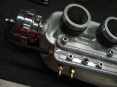
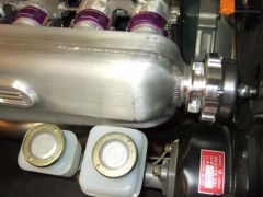
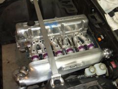
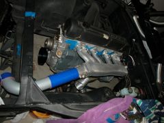
I finally finished it up. Welded the 2 halves together, polished out all of the surface machining marks, integrated the BOV, and drilled and tapped all of the vacuum fittings. Here are some new pics.
-

-
-
-
-
-

A few new photos of the "baby" after new shoes and a bath....
MONZTER replied to ktm's topic in S30 Series - 240z, 260z, 280z
Were the pictures taken on Santiago canyon? I love driving my Z on that road -
Head coolant return pipe thread size / type ?
MONZTER replied to Chemicalblue's topic in S130 Series - 280ZX
I have used a 1/2 NPT to -10 on mine, no problems at all -
check these out http://www.sivalves.com/ocforeign_valvessp_nis.html They are what I have been told Nissan Comp sells. About $8.00 each and you can buy them direct. I have them in 2 heads and never a problem
-
Head coolant return pipe thread size / type ?
MONZTER replied to Chemicalblue's topic in S130 Series - 280ZX
What is not a pipe thread? The head or your fitting? I'm pretty sure the head is a 1/2 NPT at least my N-42 and P-90 is -
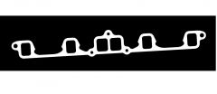
I will be making my intake gasket out of the Garolite, and then the header gasket out of the same thickness annealed copper. I just debating on how thick to go.
-
Look into a material called Garolite G-10. This is what people use to make insulating spacers from.
-
-
Custom Intake- How much can the stock ECU handle?
MONZTER replied to Challenger's topic in Fuel Delivery
I dont use the 6" long bits. I buy standard length and then use an extension. This way I have both lengths for the price of one. This is what the bit looks like. It is clog free for aluminum. I would also use cutting wax to help keep it from clogging. I rotated the TB, but it was a lot of work filling in the radius to get it to flow into the first runner. If you dont have a tig, and dont know how to build aluminum up with a tig, I would say dont do it. -
Custom Intake- How much can the stock ECU handle?
MONZTER replied to Challenger's topic in Fuel Delivery
Hi Derek, Mine was like Tony D said. It was a non egr manifold, but still had the bumps right in the inlet of the runners from the plenum, just no holes in them. As far as my mods I did, I opened the up a bunch by removing the casting bumps mentioned above. I then blended the runners into the plenum making the entry as smooth as possible. I opened up the runners the max possible but not fully concentric. What I did was make the runners as straight as possible to the port as I could. This means the runner are much thinner on the inside of the bend radius, imagine the shape looks the same from the outside, but a straighter line for the inside. Makes sence?? I used a 14" band saw to cut mine up. Put it on the table and cut it open. I TIG welded it back together. -
Custom Intake- How much can the stock ECU handle?
MONZTER replied to Challenger's topic in Fuel Delivery
The part you cant see is the problem. Mine had casting bumps right in the middle bottom of the runners where they attach to the plenum. Once you cut it in half and can see down the runners, you should be able to see how you can open up the runners to make a difference. I think the plenum is not really the problem, but the size of the runners. -
Custom Intake- How much can the stock ECU handle?
MONZTER replied to Challenger's topic in Fuel Delivery
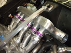
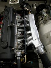
Here are some more pics of the work in progress. The engine is a stock 240z bottom end that revs very quickly to 8000, With 10.5 Compression ratio and a MSA 2003 cam it made 210hp at the rear wheels. I sent the plenum to Rebello when he was doing the port work on my turbo head. He tested it and said it should flow enough for 450hp with the GT30 I was planning on using. Dave said he has seen NA cars with heavily ported stock plenums like this making 300 + HP. If you compared the stock insides to what I was able to remove below, I don’t see how it could not help BTW I also changed the flange to a 6 bolt set-up for the earlier heads as well as injector bosses in the runners. You can also see how the TB flange has been angled to help flow into the number 1 runner as well as provide a straight shot to the core support for straight 3" tubing. Jeff -
-
-
-
The rear bumper is made in 3 pcs and glassed together, because of the undercut. Like said above, most glass parts will not be perfect. I installed mine after doing some sanding and re-fitting, and am quite happy with them. If this is not what you expected, I agree you should call them, they have good customer service and will help find a solution.
-
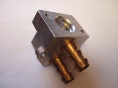
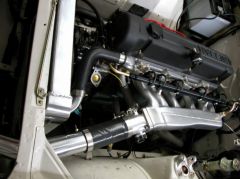
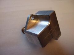
Here are some pics of the adapter body from Electromotive.
-
-