

MONZTER
-
Posts
829 -
Joined
-
Last visited
-
Days Won
28
Content Type
Profiles
Forums
Blogs
Events
Gallery
Downloads
Store
Everything posted by MONZTER
-
-
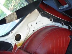
Hey Guys, I don’t know about anything other than 240's, but my cars have 4 threaded holes in the chassis right under the 1/4 window that have a recessed flat spot. I mode some plates that bolted to them and welded the bar between them. It worked out to be the perfect height and position for the belts. No cutting or welding to the chassis and it unbolts with no problem. I'll take some pictures to show you soon. Bart I will be at the MSA Autocross, trying for the first time in a year to be in control, this time with a harness. Looking forward to seeing you there. Jeff
-
Nope not yet
-
I run in a class called CSM, its not a national class, just fun local stuff here in Southern California, my friends with Z,s also run this class. I have not run for over a year and I am getting it back up and going
-
Thanks for the Reply, This is my daily driver, and I don’t want to weld anything to the body. The car is still original paint and never in an accident, so I want to keep it for restoration. Besides, I was reading on one of John C. post that you want the belt to mount close to the seat. I am really just looking if there are any regulations on wall thickness and bar diameter for local autocross events
-
I need to build a harness bar that will be used without a roll bar. I am going to mount it horizontal above the wheel tubs level with the openings in my seat, about 3" back from the seat. I am thinking about using some 1-3/8x0.83 wall CRMO that I have. Do you guys think this will be good enough as an autocross only set up. Thanks Jeff
-
-
-
1
-
I know you found something, but have you ever seen this stuff http://store.summitracing.com/egnsearch.asp?Ntt=wire+heat+wrap&N=700+400081+115+302816&autoview=sku&Ntk=KeywordSearch It is expensive, but I think it looks alot nicer than the plastic stuff.
-
Why does the turbo have to be in the stock location?? I could think of better places. Many have. Monzter
-
Yes the original F-Series bikes were made by Answer with Easton tubes. They were light and flexi. The new carbon frames are at 900gms and 50% stiffer while having better ride quality. And yes a frame and fork is expensive at 3500.00. who did you ride for?
-
So I am pretty happy today with the results of the Paris Roubaix I am the Senior Design Engineer for a bike company called Felt Bicycles. Our team we sponsor, Team Slipstream were on some custom carbon frames I was responsible for. They normally ride production bikes that I designed a few years ago, but today’s were kinda special one off's built just for this race. For some of you who don’t know the race, it is the hardest race on equipment and many bikes fail due to the pounding of the cobblestone roads. So our team had a 4th place finish with no frame failures to speak of, here are some pics from this morning’s race. It is simply amazing what we can do with carbon fiber these days. MONZTER http://www.velonews.com/article/74628/slipstream-s-maaskant-4th-into-roubaix
-

-

-

-

-
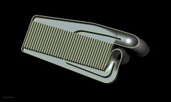
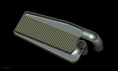
You guys ever seen this stuff http://www.clevaflex.com/ Cut six pcs all the same length and star laying out your design. Holds its shape pretty good. I was at this shop and saw them using it to mock up there designs http://www.stainlessworks.net/cart/index.php. I got some and it really helps to get your ideas figured out. I think it was like $100 for more than I needed as they had a minimum order amount
-
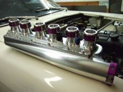
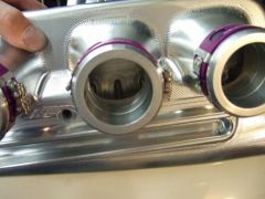
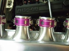
Ya right, I couldnt find it in the bends I needed. HHAHA Just kidding that stuff is waaay too much money. Its actually all 321 .065
-
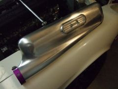
Just got home and test fit it to the car, Luckily it fits perfect, just like I was hoping. Here are some more pics:
-
-
-
-
-

