
Derek
-
Posts
1337 -
Joined
-
Last visited
-
Days Won
48
Content Type
Profiles
Forums
Blogs
Events
Gallery
Downloads
Store
Posts posted by Derek
-
-
Looks like a good solid mounting point, and a great finished product. I just thought of something that perhaps got overlooked. Since Megasquirt can be very prone to false triggers, do you think it's a good idea to be mounting the VR sensor right by the alternator?? There is a fair bit of EMI from that area. Have you run the vehicle with this mounting, perhaps it is alright this way with proper shielding???
Anyhow definately watching this thread, some real nice work there Derek. Keep it up !!!
Thanks Clint.
I used shielded wire for all my runs and I'm being careful to use single point grounding. I've got about 200 miles on it with no apparent problems. On Monday I'm driving the car for a 3 hour run down south and I'll have my laptop hooked up so I can datalog and check for rests.
Derek
-
Alright
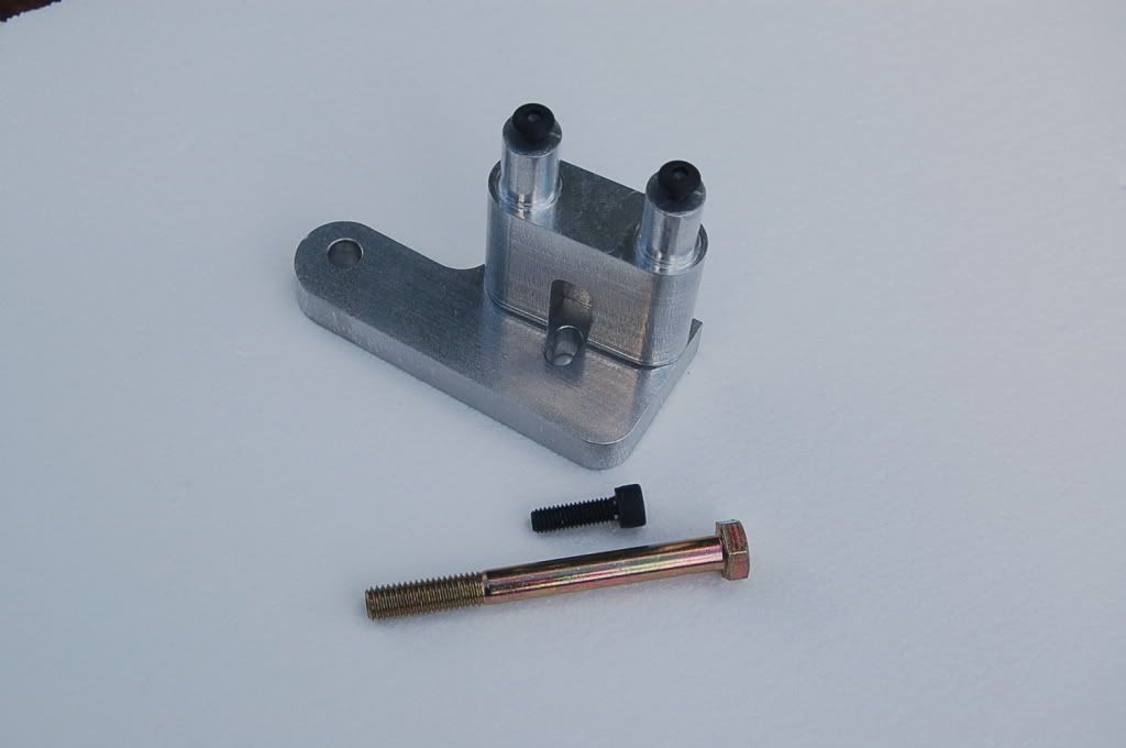
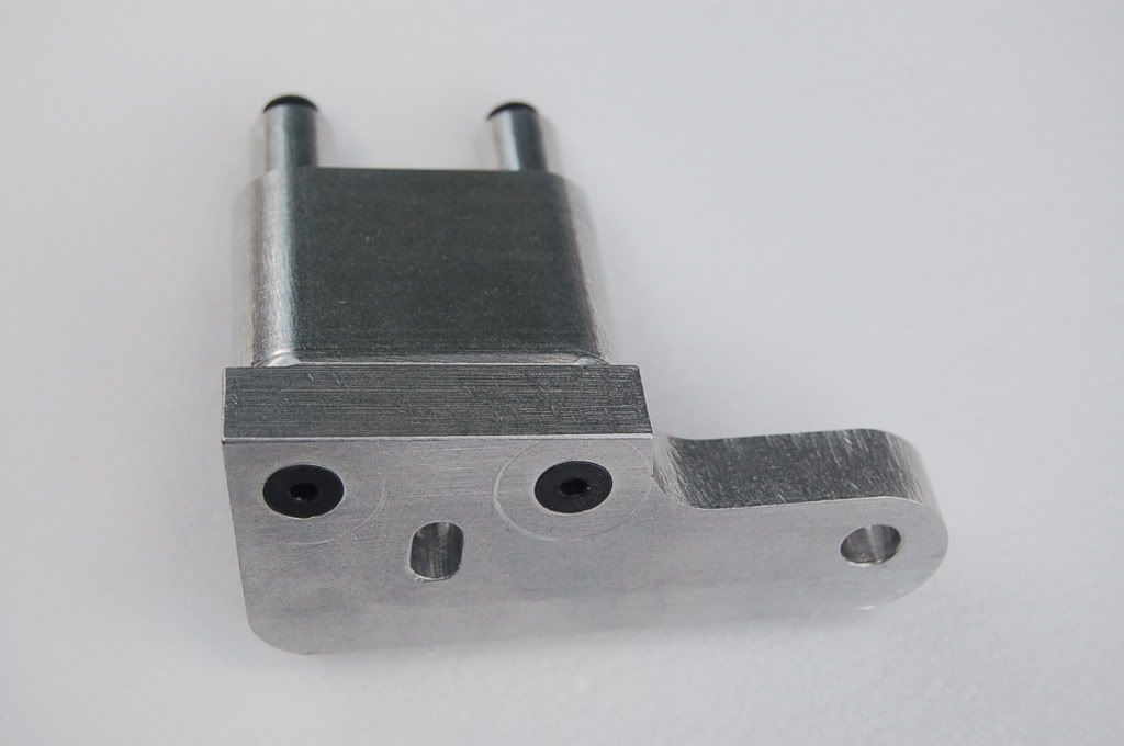
I got 6 mounts completed

The price is $48.00 plus shipping and includes the longer bolt for the timing cover and the bolt for the boss on the cover. It also includes the sensor mount bolts.
The finish is not show quality. there are some tooling marks. I did tumble them so there are no sharp edges.
Hopefully I'll have some hubs toward the end of next week.
Derek
-
wow, yeah I pretty much decided I'm going to swap in a VQ35 in place of my L28. Otherwise I'd REALLY like a set of those too. The milling I'm sure you have a file for, but I bet the lathe work wouldn't be cheap.
So as for the megasquirt, could you kind of rundown how you have yours setup? The laptop shows you have a MAP, but how've you mounted it, and I guess the O2 sensor comes later? What is your timing ring from? aren't you afraid the vibration will loosen those 4 tiny screws?
Pretty nice in anycase.
Phar
Hi Phar
The map is inside the Megasquirt unit. I'm pulling vacuum from the balance tube on the SU Manifold. No O2 sensor yet as I'm still running carbs. Right now Megasquiirt is just running the spark.
All the bolts on the front do is lock the 36-1 from turning and from going forward. The ring sits on a shoulder machined into the hub. I use blue lock tight on every thing as well as fine pitch screws which helps in vibration issues.
-
Im interested in a trigger mount and wheel (if you decide to cut some 36-1 wheels) and wheel mount!!
I'll have 36-1 wheels laser cut and I'll bore the center to match the hub.
Derek
-
I was doing some searches last night trying to find some metal fabrication forums. I know they are out there I've been on them before, I just can't find them anymore lol.
Anyway... The Z needs some under body work. Unfortunately the garage has no room for the car so all work has to be performed in the driveway.
Obviously my driveway, as most is not level. I was thinking about using 4 scissor jacks under the car to level the car out. I need to finish putting the new rear end in the car and I need it level so that I can measure driveshaft angles, suspension angles, etc.
Is this the best way to go about this?
While it's up in the air I'm also going to reinforce the frame ralis hopefully I can work around the jacks.
Let me know what you guys think or if you have some other ideas.
-Ed
Hi Ed
I've used laser a laser level on a tripod when I built my CNC router and it really worked like a champ.
Derek
-
Alright here's the deal.
I'm going to do a run of 4 wheel adapters and 4 sensor mounts. I'll keep track of my time and materials. I'll then base the price on my shop rate.
If they're too expensive then I'll keep 1 set and throw the rest up on ebay and let the market set the price and that will be the end of it. If the price is right and people want them then I'll continue to produce them.
Thanks
Derek
-
Dude I just had an epileptic seizure looking at that thing!
I think you need a warning.
Derek
-
Im thinking of doing this myself but I want to pull my lighter out and put it in there could someone measure the switch for me I want to see if it will work in place of the lighter
On my 73 I had to dremel the hole open a bit for the Honda switch to fit.
Derek
-
Another upside to the wheel adapter is that you don't have to put an old damper through the fatigue of being on the lathe. I think the experience may have compromised mine as it has a low-speed wiggle that I don't remember being there before. The wheel runs perfectly true, though. I'd probably go for an adapter wheel so I don't have to abuse a replacement pulley when the time comes.
Being able to switch dampers without machining was definitely on my mind.
One quick question prompted by Xnke's post. The photos in the other thread suggest that you alternator is in the stock position and thepickup mount does not interfere with it. Is that the case, or would
the alternator need to be relocated?
It's a Maxima alternator but it's mounted in the stock position. There's enough clearance where I can still remove the belt without any problems.
the dodge coil pack allows you to use regular plug wires, thats why so many of us run them, easier than getting the special ford plug wiresI bought the edis stuff on ebay and it included the coil. originally I was going to switch out to the Dodge but started reading how important it was to run good wires with Megasquirt. Magnecore kept poping up so I called them and they had the Ford ends. The wires cost me $97.00 including shipping and were custom legnth.
I really don't see any problem makind a bracket for the Dodge though. I'll just need someone to send me a coil.
Derek
-
If I had not already spent countless hours first putting a 36-1 timing wheel on the back side of the dampner, then moved it to the front and put the sensor next to the alternator but could not build a strong enough mount so I relocated it to the A/C side and still had a wobbly mount, so I got an A/C mounting bracket from a ZX with the two bolts in the front, mixed and matched the tensioner bracket to make the A/C work and then built two different versions of a VR sensor mount, I would certainly be interested in one of your mounts.
Well if it's any consolation pictures of your hub adapter is what got me going in that direction so I thank you for that!
Derek
-
If you can make a 60-2 wheel to that would be cool to. What are tolerances on EDIS (Sensor distance to wheel). The Tec is very close:
Crank Trigger Specifications
Trigger Wheel Size Air Gap Maximum Out-of-Round
2.5" 0.025" max 0.002"
3.5" 0.035" max 0.003"
5" 0.050" max 0.005"
6" 0.060" max 0.006"
7.25" 0.070†max 0.007"
8.25" 0.080†max 0.008"
Well the beauty (warning sales pitch ahead) of my adapter is that it's really true. The crank bolt is what it is indexed off of and I machine the step for the wheel and the bore for the bolt in one op. I'm having the wheels laser cut but then I'm finish boring the centers concentric to outside diameter.
You see we take the guess work out out your edis installation allowing you time to pursue a life of meaningful fulfillment.... or sit around and drink beer.
Derek
-
-
Can you make them that will work for a Tec-3 and a 60-2 wheel?
Sensor's like these:
Yes but you can't afford it!
Seriously though it shouldn't be too big a deal to make a clamp that holds the sensor and mounts to my mount.
Do you have a wheel or would you need that as well?
Derek
(Hey that's post # 200 for me !!!)
-
Here's where I got mine
http://www.handa-accessories.com/s2000-03maint.html
It's about 3/4s of the way down.
Derek
-
I like the coil bracket but plan to use the dodge pack
and I mounted my edis wheel ont he back of the crank pulley and clocked to to pickup on the driver side between the 2 bolts onthe drivers side of the timing cover
Well you could always switch over to the Ford pack!. When I get every thing priced up a bracket for the Dodge might not be a problem.
I thought about trying to mount the wheel on the inside but opted for the adapter instead. This way you can do the installation without removing the balancer.
Derek
-
If they can do this
http://www.devtoaster.com/products/rev/
then I'm sure an iphone app can't be too hard.
Derek
-
I've had a couple of requests to buy some of the parts I made for my EDIS install
http://forums.hybridz.org/showthread.php?t=140291
I'm trying to get a feel as to how much interest there is in purchasing the parts. I would sell everything individually. If there is enough interest I would also check into getting the 36-1 wheels laser cut as well.
Thanks
Derek
-
dang!
I sure wish you could do a quick production run on the mount and wheel!!! I would love to buy a set! wowza!
Excellent excellent work!
Thanks!
PM Sent
-
That's a radio controlled airplane filmed with forced perspective.
Look at the way it bounces when it lands.
Derek
-
Excellent design and fabrication...and nice coffee maker! Congrats on a super reliable, hands free, ignition system.
Thanks Dave
I sold my KTM that I never had time to ride and bought the espresso machine that I use every day. I wish my business decisions were that sound!
I drove the Z home last night and it ran pretty poorly. Today I learn about spark tables!
Derek
-
Went smoother than silk.
Then only thing I had to mess with was switching the sensor wires around.
I got it running in limp mode first then went with megasquirt. I even nailed the initial timing on the 36-1 ring!
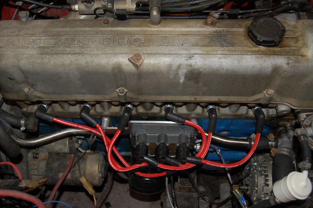
The Magnecore wires are really nice. They only took about a week to get here. I was skeptical at first about using the Ford coil but I kind of like the way they snap on.
Here's a shot of the wires. I'm planning on getting some looms. Taylor makes a nice 6 cylinder set that will work really well.
I know my engines really ratty. After I get my manifold done and working I'll be ripping the top end off as I have a oil leak between the head and the timing cover. It will be getting a major detailing then.
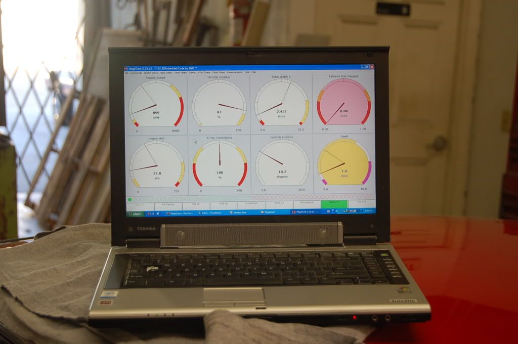
And here's the obligatory laptop on roof shot
A big thanks to all the pioneers on HybridZ that went before me. All the info made this a real piece of cake.
Now for the road test and the dreaded noise issues. I hope they're minor!
Derek
-
5.25" to the point where the wires come out of the connector.
I can sell you a like-new one, cheap, I just pulled out of my RX7. Has wiring, mini-filter and a nice heavy-duty insulator instead of the flimsy foam.
Thanks for the dimensions.
PM sent.
Derek
OOPS just reread the post. I think your talking about an in line pump. I'm looking for dimensions on an in tank.
-
I'm thinking about making a surge tank with an in tank pump something like this
http://www.geocities.com/hrayhouston/antisurgetank.html
I'm going to fab it out of aluminum. I need to know the overall height with the electric plug on to see if it's feasible to make it small enough to fit between the tank and the mustache bar.
Thanks
Derek
-
Wow Pete that really sucks. The fire really adds insult to injury.
Derek


Looking for new A/C vents
in Interior
Posted
Ok Big favor department.
I'm going to be redoing my center dash section. Here's what I have now.
I'll be making an entirely new plate.
I'm going to move the Vintage Air controls up to where the vent is and put vents in the section where the controls are currently located.
This gives me a working area of 6" x 2 1/2". I'm looking for a single unit with 2 separate vent assemblies. I'd like to have the option to close them off individually if I can.
If you have a car (any make) that has vents that fits that description can you post the make model and year.
I know it's a lot to ask but I've already bought a couple of vents on ebay and it's just not working out.
Thanks
Derek