
Derek
-
Posts
1317 -
Joined
-
Last visited
-
Days Won
40
Content Type
Profiles
Forums
Blogs
Events
Gallery
Downloads
Store
Posts posted by Derek
-
-
I have not investigated the 'vented cap' but if it was a one-way valve that may well be workable under EVAP restrictions at the time. It for sure could not let anything vent out. And from an early 71 240 I personally witnessed suck down the filler neck flat...it has to be the gas cap 'with ears' that has that kind of device present. I just don't know why they would bother with the EVAP Filtered Air setup if that was the case though---a one way diverter valve would have been much cheaper, as the makeup from the cap would be more than enough.
Here's more info for the "wiki"

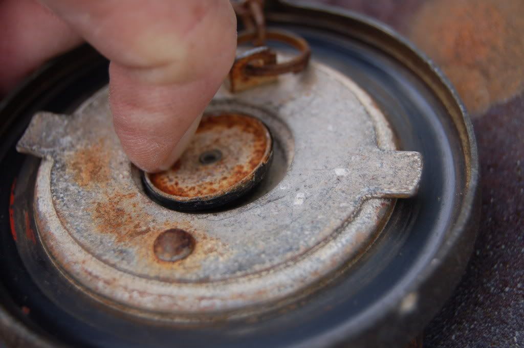
I never knew they were vented either. I was looking for alternatives to the way I was currently ventiing so I investigated the cap.
Derek
-
Well I got back on the old google and came up with a source for the DAG 213 that will sell me a quart. It's 95.00 plus shipping. They're going to see if they can sell me a pint but either way I'm going for it. $95.00 is very cheap insurance.
Her's a link to the data sheet if anyone is interested
http://www.laddresearch.com/SpecSheets/LaddDAG213.pdf
It's a baked on product. I'll have to do some trials first. Not sure how resilient it is. If it's too hard then the high area of the butterfly will just hit the DAG and continue to leave a gap. If it's flexible it will allow the butterfly to sink and create a seal.
Derek
-
A common solution is to engineer a tiny bit of play ( 0.020 - 0.050 ") into the linkage between the master and each individual throttle. That way, at idle, the individual adjustment screw controls that runner, allowing very fine adjustment. As the go-pedal is pushed, the master takes up the slack, and then controls all of them. Ideally, the play is equal for all, so that off-idle synch can be performed. But at WOT, they are all open fully against the stop anyway, and so any play becomes moot.
Carter
Hi Carter
Unfortunately that would require a redesign on the levers and linkage so that won't be happening right now. Thanks for the input though.
Hey Derek:I've been watching your thread! Nice work Buddy! Throttle Plate seal is critical, more than .002" "Butterfly to bore" clearance and the IAC Valve is a MUTE Point, as it will not idle less than 1300-1500rpm. The smaller the Displacement of the motor and the larger the ITB's are this Tolerance goes down from there!
Kevin
Hi Kevin
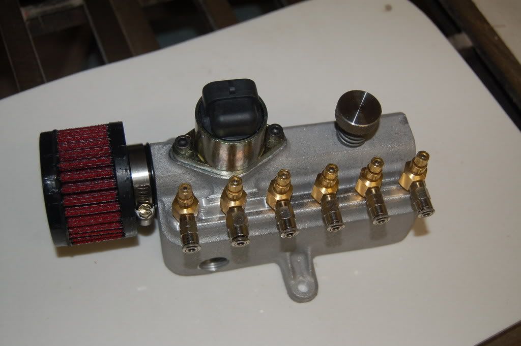
Well it was your idea to use the needle valves to begin with.
I have spys everywhere!Nice IAC Unit, you been Peaking in my Computer?
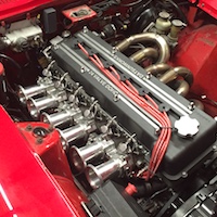
Actually I was looking at the IAC housing at DIY auto tune and the log on your site and figured that needs to be all one piece. Then the visual of the needle valves with the lines running over to the runners just sealed the deal. I had to have it!
Well this sounds like something you need to INSTALL it all for first. Really, You should start off w/ all your needle valves shut and see how much air leakage you have in your ITB's. the IAC should allow enough air through to get you idling. I though you were going to use that BMW/NISSAN goo stuff to seal the throttle platesPhar
That's my original plan. I'll establish a base line on the butterflies and then decide if I need to make changes. Right now I'm trying to get a feel for all this so that if I have a problem I'll have plan be ready to go. I can't get started on the install yet so I might as well work this crap out in the meantime.
I couldn't come up with any unless I bought $500.00 worth. That coating is really more of an antifouling/sticking compound anyway.I'd rather have it work without anything. This is really just a problem with the prototypes. There were a couple of areas I needed to be more precise on and kind of blew it. The embedded stainless tube idea is a winner. I just need to make a couple of changes in the way I align everything prior to the pour.I though you were going to use that BMW/NISSAN goo stuff to seal the throttle plates
Well It's my understanding that the needle valves introduce a small amount of air just behind the butterfly but in front of the balance tube. This simulates cracking the throttle plate a little. The needles are just for synchronization. The base idle is set manually with the large idle screw on the log. The IAC is for controlling cold start.one thing to keep in mind is that since all your TB's are connected via the balance tube, each of your needle valves are going to have an effect on each of the other cylinders. opening one valve even a little will allow air into your balance tube rather than front to back of each TB. isn't that the function of the IAC?Maybe I'm wrong, and perhaps I should have spoken up sooner, but these balancing valves aren't going to be very useful in that sure they work for carbs to balance pull from cylinder to cylinder, but for EFI, especially on a batch fired system (MS) they're just going to make it harder for the IAC to do it's job controlling idle. if you didn't have a Balancing tube between each cylinder & between the manifolds, then yes these valves would be invaluable in balancing flow at idle. Using just one valve should allow you to adjust your idle. This, and the IAC could have been built into your manifold. I had an idea for this that you could just mount to the end of the balance tube by Cyl 3 6 or better between the two manifolds. I'll draw up a pict...
of course, I've never built a manifold, and my EFI experience is limited to playing with GM EFI on a couple jeeps so maybe I'm wrong. if I am, please explain ...
And as far as mounting the IAC in the manifold it can't possibly look as cool as the log...I mean did you see that thing!!
Sniff...Sniff... I'm so proud....
Derek
-
Hey Derek. Im going to jump in here on the synchronizing of these things. Ive synched many of a motorcycle carbs and ITB's. There is a reason that the industry standard for doing this job is the mercury sticks. They just plain work. And Id say buy 2 and do them all at once. It will make your life so much easier. It is possible to make your own if you have a source for mercury. Hell my dad even went on the cheap before i had a set of the mercury sticks and used engine oil instead of mercury. You wont be able to get a "true reading" but it will read the same for all cylinders and its more about that than getting a certian number. Do a google on making your own and im sure you can find some plans for it. And then with your abilities im sure you can make something work for ya.
Well I figured with your background I'd be hearing from you on this one!
That will only match idle synchronisation. And all the throttles need to be connected to speed up the process. When you open one cylidner, they all get a higher vacuum.Having all six on a manifold 't'd' into his manifold block would be the way to set idle. With the over the horn gauge, you can quickly jump from each barrel to the next quickly checking where they all are and make the idle adjustments. You can get the off-idle done while the engine is warming up, and have it damned close by the time it's at operating temp to do the idle synch with the manifold needle valves.
INFORMATION OVERLOAD!!!!
I need to backup a bit and get a little egimikated on this hear synchronization thing.
So we have idle synchronization and off idle synchronization. In a perfect world the butterflies would be air tight and the idle would be handled with the base idle screw. there would be no need for idle synchronization. The off idle synchronization would be handled with the needle valves on the log.
Since I built this with a broad ax the butterflies are not perfect so I need a method of synchronizing them at idle. Or I need a way to get the butterflies as airtight as possible at idle.
I was running under the assumption that when the needle valves are set at idle then this would make all things equal the the off idle would follow suit.
Derek
-
Just how in the hell am I going to synchronize these things!
I'm thinking my old Uni-Syn just ain't gonna cut it.
Motion Pro sells this:
http://www.motionpro.com/motorcycle/partno/08-0411
And Morgan sells this:
http://www.carbtune.co.uk/c.com/index.html
Obviously since they're for a four cylinder I'll have to do it in stages.
The Morgan seems to get generally better reviews.
Thanks
Derek
-
Never mind its in May this year. You BETTER have this together by then!!!!
Man I really hope so!
-
Fantastic work, as usual Derek.
Pete
Thanks Pete.
Looks pretty darn cool! Me likee! I understand on the bank account side. it's after Xmas and $ is short all aroundLooks like it'll work, How hard was the machining for the IAC at the base?
Phar
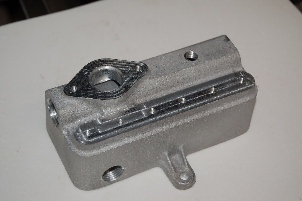
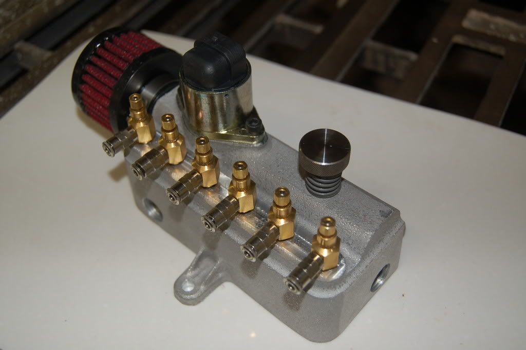
It was really straight forward. Drill a hole all the way through to the vacuum passage. pocket for o-ring, pocket for idle valve.
I could see TWM buying that piece and charging $1500 for it...So If I charge $1400.00 I'll be giving everyone a bargain!!!
It does look spiffy though. Maybe $1450.00
Derek
-
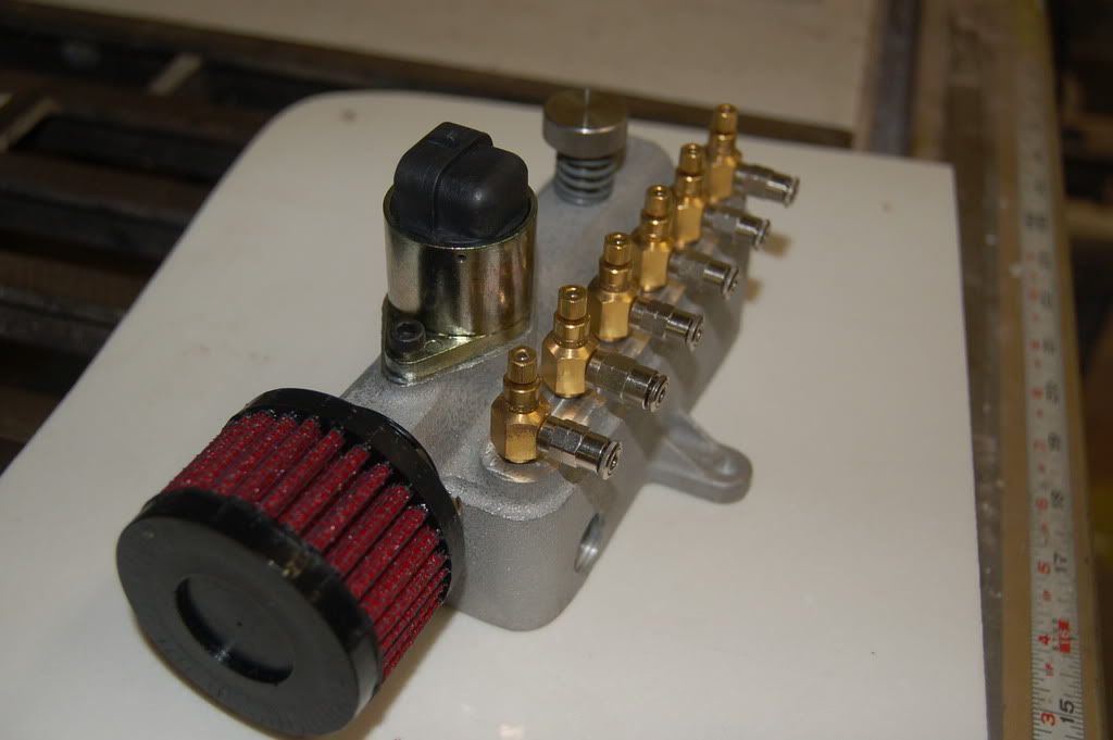
I'm doing a bunch of 3D scanning so I had some free time in between setups so I did the machine work on the log.
Now that's pretty tough looking!
The spring under the base idle screw will be replaced with something a little nicer.
The production model will have bigger mounting tabs as well as a second core for the vacuum side. I did a simple cross drill on this one but there was a large amount of mass in the casting which can cause problems in the metal.
The second core will lighten the casting as well as create a larger reservoir for the vacuum.
Derek
-
Okay so you gonna do the install this coming long weekend? (assuming you're taking MLK day off)
Phar
Not this weekend.
Just paid all the bills and checked the bank. YIKES!!! Warning...account below comfort level.
Probably going to take me a couple weeks to get back ahead of the curve.
Derek
-
Wow. N I thought I was geeky... hehehe
Well, it all looks like it is a doable situation, though from what I understand MS doesn't do sequential injection so even if you find that your cylinders aren't even, how are you to fix them without changing to some more expensive EFI computer or piggy back?
I'm still a fan of GM EFI, but without a piggyback, you can't change the individual cylinders either. Seems this project has become much more expensive.
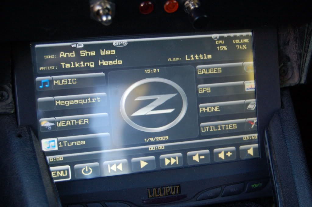
Your Carputer looks awesome! I'd thought many times about building one. Is yours touch screen?
it certainly mates your Car requirements:
Look cool.←
Look really cool ←
Actually run ←
yup passed
phar
Thanks Phar
The individual EGT sensors are merely a way for me to analyze the performance of the individual runners. Assuming the injectors are flow matched (supposedly they are) and Megasquirt delivers consistant amounts of fuel (it should) then any anomilies in temperatures can (sorta maybe) be atributed to intake design or assembly.
The carputer has a 7" touchscreen.
Derek
-
Crap I wish I had seen that before I got the kit from Dakota. I'll get ahold of Rostra. I'll bet they sell the cable separately.
Thanks for the heads up
Derek
-
What the heck... WOW this thread kinda budded and thrived over the course of today, that was unexpected... "divorced" lol.
I only posted about the EGT gauges to get sappy and talk about how I liked the dual needle sweep, because I'm used to seeing it in the old fast cars from when I was a little kid... (and I thought I helped to illustrate the low resolution obtainable from one of them, not contradict it) but now all of a sudden... carputer? I don't think I've bumped into that term yet, although the concept has been on my mind for nigh a decade now... must research soon, thank you!
Yes it's my first divorce! So Sad.....
Everything you ever need to know about carputers
http://www.mp3car.com/vbulletin/
Right now mine has my music, GPS navigation, and I integrated Megatune into it. I'm working on a better solution than Megatune as the gauges are tiny tiney incy wincy little things!
Derek
-
Oops, almost forgot, if you use the AD595, remember the output is 10mV/degree C, not F. Also, look at McMaster-Carr for thermocouples.
Carter
Hi Carter
Glad to see we finally found a subject that piques your interest.
Thanks for the info. I checked Mcmaster for the thermocouples but they were a bit pricey. Probably better than the ones I'm looking at but still pricey!
Ok. they made it way too hard to figure out something so simple as exactly what you can and can't do with an analog input signal. My wife really isn't so happy i'm spending so much time on the PC tonight.so what i figure is that you need at least 1700*F (~927*C) on your readout. but that gives you just under 10V output from the AD595 IC. so if you can drop that voltage by half across the scale then you should be able to use it with the brain.
then its just a simple matter of using their program to double the voltage value read by the brain and then use their handy dandy included celsius to fahrenheit conversion factor already built in to the program and you should be golden. but because your dividing the voltage by two you are doubling the error factor of the chip to 6*C add that to the 4.88mV resolution of the brain and you get an error of about 10*C or 18*F i would guess. thats pretty high.
only problem i see is that just adding a resistor to the output may not have the desired effect of cutting the voltage in half. i have no idea how the circuit inside the IC will affect the overall resistace over the spectrum and that just adds more room for error.
but, like previously mentioned, if your only using this to measure the difference between the individual cylinders, not to get the exact temp of each, it should work fine. at least good enough to give you some warning before one of your cylinders goes too lean and burns down.
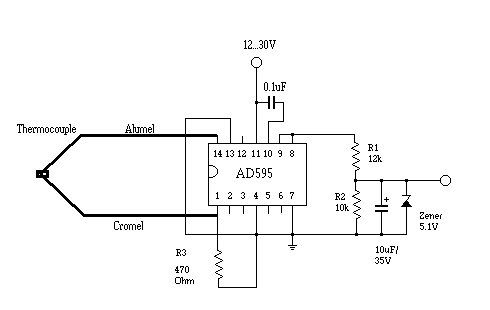
Check out this schematic from the innovate site:
And here's the description from Klaus who I think is an engineer there:
"Attached is the AD595 circuit for EGT measurement.
With a minimum of 13V supply voltage it measures up to 1100 deg C (2012 deg F).
Set the LogWorks input to:
0V = 32 deg F (0 deg C)
5V = 2012 deg F (1100 deg C)
The AD595 can handle a supply voltage of up to 36 Volts. So it can run on a car's 12V supply without any regulator. Minimum supply voltage required to go up to 1100 deg C is 13V, which should be no problem for most cars. Lower supply voltage just reduces the max temp, not the measurement.
The AD595 outputs 10mV/deg C, up to a max of supply voltage - 2V.
The divider circuit of R1 and R2 divides the AD595 output by 5/11.
R1 and R2 should be 1% resistors. Wattage for the resistors does not matter (1/10th Watt is enough).
The Zener diode protects the LM-1 if the AD595 fails.
The capacitors of 0.1uF and 10uF filter noise.
R3 is required only if the TK used has an isolated junction. On those there is no continuity between the TK wires and the TK body.
Type K TKs have color coded wires. Yellow and red. I don't recall which one is which. If you hook them up wrong you won't damage anything, but it will not measure."
You can see he's using R1 and R2 to reduce the output. I don't know if this method reduces accuracy or not. Keep in mind they're using this for EGT reading to a 0-5v gauge so it should work for the fusion brain.
I found this place (I'm sure there's others) to make the circuit boards.
http://www.expresspcb.com/index.htm
I was toying with the idea of making them myself but for that kind of pricing it's just not worth it.
I'm not sure how many inputs to have on the board. Once I'm done testing the manifold 6 inputs should be plenty for any temp sensing I want to do.
One for EGT, one for oil temp, ok that's all that come to mind but I'm sure there will be others.
Derek
-
Ok, i've been quitetly following this project of yours for quite a while now and I've very impressed with the project! but now i have to ask a question.
i just spent the last hour and a half looking into this fusion brain thing. its very interesting and i think it will solve my problem of how to get additional features into my Mini ITX computer I'm going to run in my car without going through the very limited options megasquirt offers. mainly the amount of sensors i want to feed into it has been the problem. also the lack of quality megatune offers.
anyways, how are you planning on feeding the K-type thermocouples into the brain? i've been searching their fourm section like mad on MP3car.com but can't find much. i have some very elaborate schematics i drew and tested for an standalone, digital EGT sensor readout with built in alarms but i have to use the AD595 IC to process the data from the thermocouple. are you planning on building a complete second board to process the data from the thermocouples and then feed it into the brain in a 0-5v format? not hard to do once you figure it out but it's a little bit of work.
sorry to take the thread off course.
Well about 5 hours ago I had no Idea what I was going to do!
At this point I'm probably going with 6 of the AD595 on a separate board.
Digikey has them for $11.00 each.
I found this post on the innovate forum that has a lot of good info:
http://www.innovatemotorsports.com/forums/showthread.php?t=371&highlight=ad595
You probably have this but I'll post it for others
PDF for the AD595 http://www.analog.com/static/imported-files/data_sheets/AD594_595.pdf
Am I correct in thinking that you can vary the range that it reads by changing the value of a resistor or am I confused.
I was planning on getting the Fusion Brain anyway and I have a Fluke pyrometer so I can always read the thermocouples individually.
We may want to spin this off to another thread if there's interest.
Derek
-
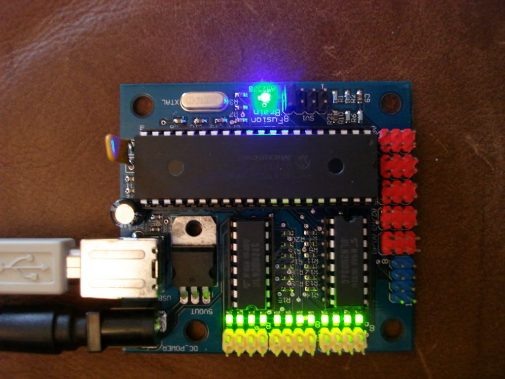
Here's what I'm thinking
6 of these
Running into one of these
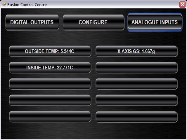
http://www.fusioncontrolcentre.com/FusionStore//catalog/product_info.php?products_id=62
hooked up to this
My current carputer
With this skin
But with 6 inputs labeled cylinders 1-6
I'm pretty sure this is doable. I just need to calculate whether the resolution of the fusion brain will give me an accurate enough reading. it's 10 bit over a 0-5v input if any of you geniuses out there know what the hell that means. I don't!
The software has data logging over all the inputs.
$59.00 for the brain
7.00 each for the thermocouples
carputer already installed
Cool factor........
Priceless
Derek
-
The Aussie dollar is most often referrenced to the USA dollar. When I said our dollar was not doing well, I meant that it wasn't doing well to the USA dollar.
Haltech and Motec are both Australian Computers. Hence the comment. Sorry Derek, it is late over here, I will stop taking up all your thread.
No worries (in my best yank does Australian accent)!
The individual bungs are in each tube of the header so that after I have the car running and tuned I can then analyze the mixture on each cylinder by screwing in an 02 sensor and hooking it to megasquirt (or a standalone reader if that's problematic). That way if there's a glaring problem in the design I'll be able to gauge weather changes I make are making a difference.
Derek
-
Divorced from Derek's cast intake manifold thread http://forums.hybridz.org/showthread.php?t=129941 --RTz
Thanks guys. Sounds like I'm heading in the right direction. I'll pull the vacuum for the map sensor from the log.
Since this is a test mule of sorts would it behoove me to weld in 6 O2 sensor bungs in the header while I have it off. This would allow me to read each individual cylinder. I'd have to move an O2 sensor from hole to hole but it's doable. I can make the bungs up on the lathe so it's not a big deal.
Any thoughts?
Derek
-
If ya do t this, document it well and let us know!
No problemo.
Derek
-
My plan is to use this 8K signal generator
I'm not positive on this but I don't think there's enough room between the tunnel and the transmission for this. I might need to locate a 90 degree speedo cable adapter or a cable that's about 6"
long with females on both ends.
derek
-
Id like to know if you can get this to work also. Im really wanting to install cruise control into my Z for the 12hr. trips from FL to TN. or from TN to KS
Hey Jeff I just got the Rostra setup for Christmas. I'll be installing it right after I install my manifold. It looks like a nice system.
Derek
-
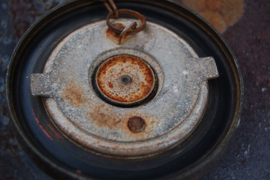
I was looking at my gas cap the other day and I noticed that it has a one way flapper valve in it allowing air in the tank but not letting anything escape. Don't know if it works or not as I have a vent line on mine but that's the design of the cap. there are 2 ridges that run across the cap. I used to think these were strengthening ribs but upon closer examination they are the vents.
Derek
-
I have these as well as the Spal central locking system and couldn't be happier. Smooth quiet and fast.
Derek
-
No, I do not believe it is vented to the fuller neck, should I just run a line to it from the small feed on the tank?
It's been a while since I did mine but there's a large diameter (3/4" i think)
nipple on the top od the tank. I ran a 3/4" fuel hose from that through the car and into the filler neck.
Derek
-
Thank you Tony D. Also, is there a reason my tank only fills about half full? Does not having an expansion tank have something to do with this? We bought the car without one.
Did they vent the tank to the filler neck? If not this may be a problem.
Derek


Fuel lines....will they work for fuel injection?
in Nissan L6 Forum
Posted
I'll get right on it!
Derek