
Derek
-
Posts
1317 -
Joined
-
Last visited
-
Days Won
40
Content Type
Profiles
Forums
Blogs
Events
Gallery
Downloads
Store
Posts posted by Derek
-
-
Seeing it mounted. I was thinking about the PCV , you could run a tube down into your balance tube between the manifolds. It would help milage and actually lower pressure in the valve cover. tho your original idea of using a small filter there would work well too. just a thought since positive ventilation also pulls fumes from the crankcase and neutral ventilation relies on blowby to push the fumes out. What are your thoughts?
Hi Phar
The PVC is going to be mounted on a 90 degree boss that's welded to the bottom of the balance tube between 2 and 3. This way the stock hose can be shortened and still utilized. I'll have a K&N breather on the VC for now.
Just say no to bling! No colored anodizing either! Think old school 70's factory race team.
My plan on the valve cover is to clean it up and then start out walnut blasting. If that won't do it then I'll switch to glass spheres then back to the walnut shells. Same with the water outlet. The thermostat housing is new and off of a 280 as I have to mount the coolant sensor in it. The valvecover, timing cover, water outlet are all die cast. That's why they have a smoother finish than things like a manifold that's sand cast. So if you go at them with too heavy of an abrasive they start looking a little rough.
Right now the plan (until it changes again) is to run a cable from the existing bell crank under the the manifold to a lever on the bottom of #4 throttle shaft. Better than driving it from #6 and very workable. I have 1 extra lever so I don't have to set up to do a run. By using the bell crank I can do a stealth mounting of my cruise control and snake the cable behind the brake booster. I hope.
I stripped the manifolds down to make all the final mods and re machined the flange angles. Had to pull 4 degrees off in order to get hood clearance. Looks better too.
I have to move the TPS to #5. On #6 it's too close to the header tube.
At this point I'm transferring the manifold and header over to the mock up head so I can start finalizing the boss arrangements. After everything's good to go it's time to goop.
And oh, I'm supposed to make a living while all this is going on!
Derek
-
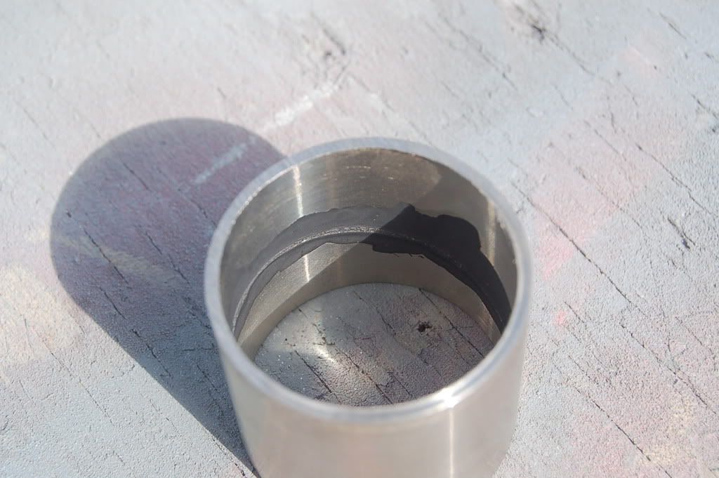
It's a dessert topping and a throttle body bore sealer.
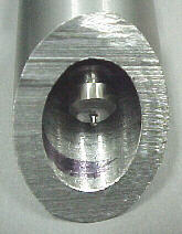
This stuffs the sh!t! I did a test on a spare tube and old butterfly. I balanced the butterfly in the tube and it had a lot more gap than my worst bore. I painted a fairly liberal coat on both sides of the butterfly. I let it flash for about 20 min. and then baked it at 350 for an hour. Perfect. The goop maintained its structure and the bore was air tight. The butterfly popped right open and out as there wasn't a shaft.

You can see the sealing ridge it left. The camera makes it look a lot larger than it is. After baking the stuff is uber tough. I couldn't scratch it off with a set of needle nose pliers. I put the butterfly back in and even though it wasn't in the same exact spot I couldn't see any light.
Needless to say they'll be getting the Goop 213 treatment.
Oh and my hood is staying on and unmolested.
Derek
-
I will measure a dodge coilpack with the calipers, and take some pics to verify I did it accurately. I have to go out to the farm to get it, might take a bit.
Cheers, Clint
Hi Clint
I have a drawing of a coil pack. I really need the pack itself so that I can make sure the offset on the standoffs is correct.
Derek
-
All that and a mechanical fuel pump
Love it man! Keep up the good work.
What and you didn't notice the coil and the Hi-fire box with an EDIS system.
This here's a very special Z car!
Derek
-
Thanks guys.
This is the part I've been waiting (dreading) for. What fits what doesn't fit.
The hood issue is really minor. the hardest part of that is pulling the Kurt vice off of the mill and wrestling the angle table in. The setup is pretty simple.
Everything fits right now underneath but when I tilt it I'm going to have to move a few bosses that will hit the header tubes. But that's why they invented the word prototype!
but yea, the angle does look a little funny to me.
also, you mentioned that you may redo the lines? If it were me, i would leave the lines all parallel at the main bend around the back of the head, and then open up to meet the spacings on the block.
It'll look neater, and transition around the head a bit better.
The fuel lines were one of those "I have a vision" deals but when I started actual fabrication there were a lot of issues that popped up. If the concept of this works out in the August heat then I'll redo it. I had the lines all bent before I realized I need to have enough spacing on the fuel block to get a line wrench on the fittings so that part is especially convoluted.
The vacuum block fits no problem. I kind of wish there was a little more separation between the firewall and manifold but that's one that won't be changing.
It looks like the best way to handle the throttle is going to be with a cable. I was hoping that I would be able to make the existing bell crank on the firewall work. Theoretically I could put a second bell crank closer to the hood latch and run it from there but it's starting to get crowded over there.
I don't know whether to run a cable directly from the pedal or to go from the bell crank. I had also hoped to drive the throttles from the rear lever only, leaving the top of the manifold clean but I'm getting a little nervous on that setup. I'll probably play it safe at this point and run it over to the center tie bar. I'm using a stainless shrouded cable so it won't look too bad.
I may have to move the TPS over to another shaft as it looks like it's going to be a bit close to the #6 header tube.
All in all not too bad for a first fitting.
Thanks again for all the support. This probably wouldn't of happened without you guys.
Derek
-
Wait for it
.
.
.
.
.
.
.
.
.
.
.
.
.
.
.
.
Keep waiting
.
.
.
.
.
.
.
.
.
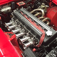
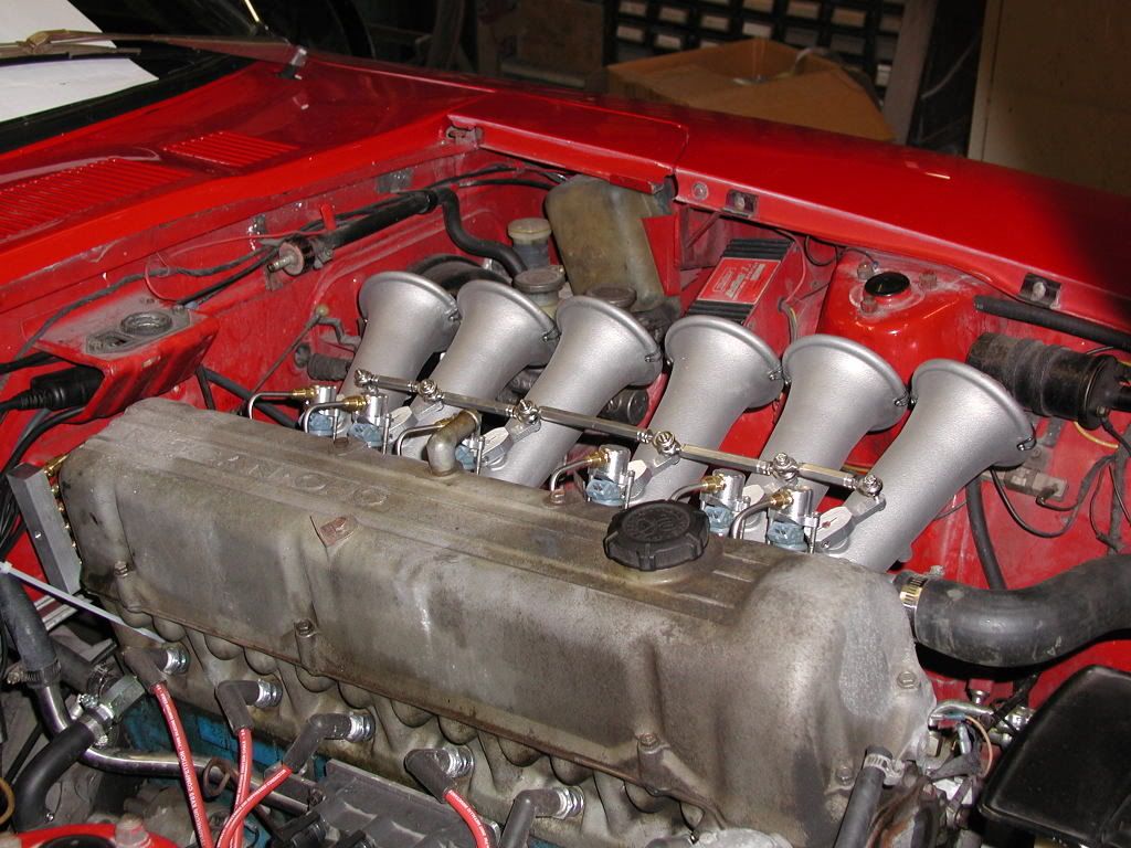
BAM!
Ok the scuzzy ass engine makes this pretty anticlimactic but I promise I'll improve that before I do the final install. It really looks a lot better in person.
And now for the bad news. I'm not really happy with the ascetics of the angle of the manifold. I feel it's pointing upward a little more than I would of liked.
Now for the good news. It hit's the hood so I have no choice but to fix it!
I designed it to have the best possible (in my mind) angle into the head. I knew it was going to be close so I have plenty of meat on the intake flange so I can bring it down a few degrees.
It's definitely Tuff looking though
Now comes the hard part. Staying focused on work while this is going on.
Derek
-
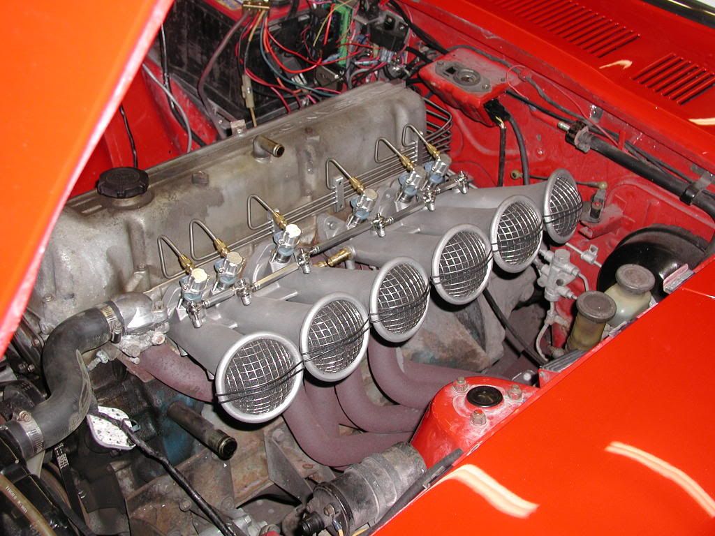
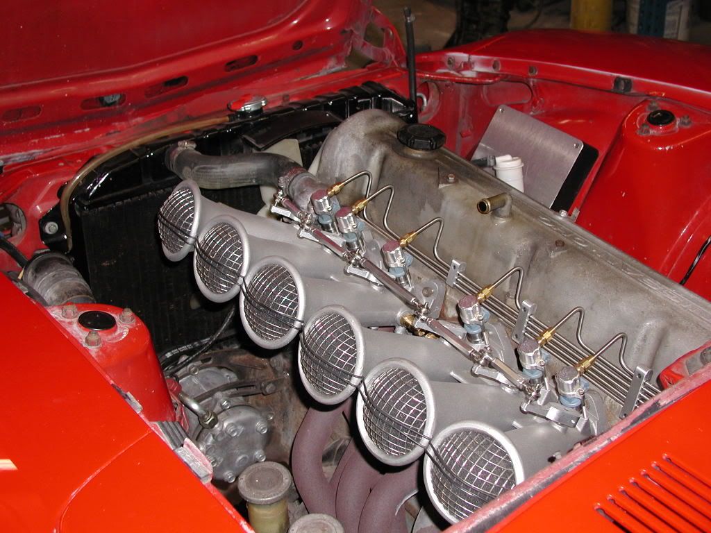
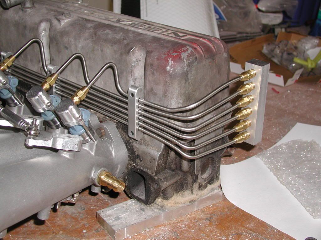
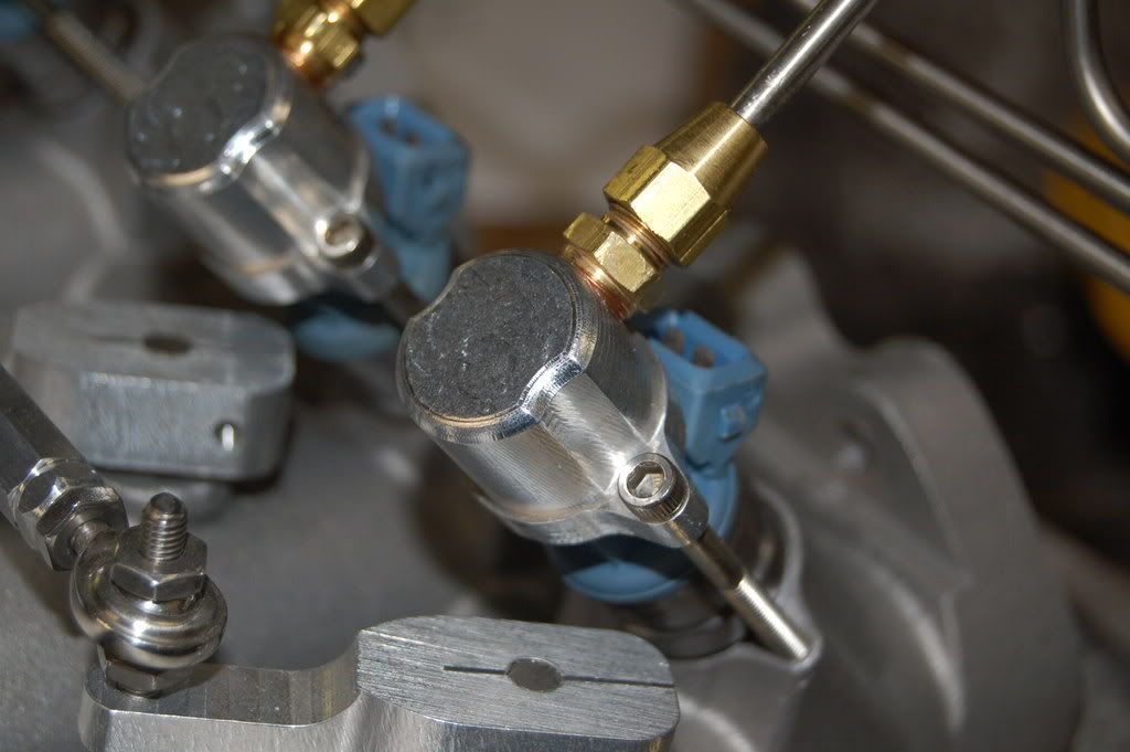
Got everything done for the test fit. The last part was the injection line looms.
My plan was to anchor the looms with insulators to stop the heat transfer. I changed plans after the first set and decided to let the lines free hang and anchor the fuel block to the head. There's nylon tubing between the looms and the stainless lines. Mostly to stop electrolysis but it will help in heat transfer.
The fuel block has the inlet on the bottom and the regulator goes on the side.
There's a decent amount of air gap between the valve cover and the lines. If there's a version 2.0 I'll bring them even further out. I'm pretty happy with the lines as a first effort but I'd relly like to scrap them and start from scratch. Wouldn't be prudent at this point though!
-
I am in for everything including the trigger wheel, looks like a great package at a fair price. Have you considering offering the option for mounting the dodge coil pack?? Some people don't wan to run the strange FORD wires, although the ends do look like the would do a better job.
If someone sends me a coil I can make a bracket.
PM sent
-
Got her running with MSII. Was runnig MS-Extra last year. EDIS isn't advancing the timing for some reason so it is running in limp-home mode (10deg advance).
http://upload.streetfire.net/video/Dual-Throttle-Body-Datsun_501660.htm
No Fair you got yours running before mine!!
I had the same problem with my install on the EDIS. Had the saw wire in the wrong spot. My 49 year old eyes let me down!
Great work Pete!
Derek
-
Alright here's the deal.
I did a few hubs for three members to get a feel for it before proceeding.
Here's the prices
Everything includes the required bolts.
Sensor mount $48.00
Ford Coil bracket $25.00
Hub 85.00
Laser cut 36-1 trigger wheel... That depends. If I buy 4 from the laser cutter it's $50.00 each. If I buy 8 it comes down to $30.00 each. IF I can get 4 people to commit to hubs and trigger wheels I'll buy 8 and hope to sell the rest over time.
If someone wants to send me a dodge coil I'll make a bracket for the same price.
So there's no confusion this is for a damper with 2 pulleys only.
I offered to machine the escort wheels for the three people that bought the hubs for $15.00 each. The bottom line on that is It's going to be cheaper in the long run to just use the laser cut wheels. The escort wheels are all (so far) slightly different and one was bent pretty badly.
So we need 4 brave souls to buy hubs and wheels so I can order 8 and get the price within reason.
Let me know
Derek
-
I wouldn't move the pintile caps. Strange things happen to the injector spray pattern when you do that---unless they are talking about somie sort of pintile/o-ring combination fitting like an MSD GM style injector or something.
Nissan clamped their injector bodies down using that big rubber ring, and a smaller flat o-ring on the pintile. I mounted mine using a standard O-Ring on the nose sealing like Nissans design, with the body clamp and everything. This let me the freedom to free float my fuel rail separately due to the close areea in which I was working. I got it all to fint inside, but there has to be an easier way. When I get the time, I'll work on it some more and eventually get it to where I like it.
Too late!
Since I opted to go with the procedure I mentioned earlier the manifold won't even accept an injector with a pintle cap.
I guess we'll just have to see how it runs.
Derek
-
The injectors should be free-floating. They should be able to rotate. The fuel blocks should be at a fized distance to affect a seal, but not solidly clamp an injector. It should float slightly axially, bottoming before a seal is broken, and should easily rotate when everything is bolted down. A firm clamp will not only transmit a LOT of heat (o-ring being the only thing touching doesn't allow direct metal-to-metal transfer through conduction) it has a chance to distort the body when something grows through heat expansion.
Hi Tony
I based my injector mounting on this info
We usually make these out of 1 inch bar stock. We like to seal the vacuum side of the injector with a 5/8 ID- 3/4 OD O-ring slid over the nose of the injector body. This will work on any standard injector. You can pull off the stock O-ring and pintle cap. Bore the bar stock to .640-.650, straight through. This allows a slight air gap between the boss and injector to reduce heat transfer and fuel boiling. A .740 counterbore, .040 deep is machined at the end for O-ring retention and sealing. We usually cut off the bosses at 45 degrees so that they are about 1.35 to 1.5 inches long. This is a good entry angle for many injectors into the runner and is an easy angle to saw at.
Taken from this site http://www.sdsefi.com/techinta.htm
At the time it seemed like the best way to go. There is quite a bit of air gap between the manifold and injector. The base of the injector body is sitting on an o-ring . I'm afraid if I don't have the injector clamped down I'll have a vacuum leak at the base of the injector.
I did use Tefzel as well due to my concerns with the heat. If it can lay across the bleed air plenum of a GE F100 Engine in an F15C, I figure it's good enough for me. Aircraft Spruce has it available, shielded as well for those TPS and CAS triggers.After putting together a few CNC retrofits I'm a big fan of multi conductor shielded wire. I'm using it on everything. injectors, sensors, the works. And single point grounds as well. I learned one thing early on, noise sux.
Derek
-
How about running a second stainless line to each injector like you have for the fuel and putting the wires through that. You could somehow clamp the tubes to each injector together, with the wiring one on the bottom.
Actually my plan is to drill a small hole in the web and run the wires straight down and under the manifold. They'll go into the same loom as the balance vacuum lines and pop out at the log. I'll put the upper wires in gray heat shrink so they'll kind of disappear. I'm waiting until I get the header on my mock up head so I can see what kind of room I have to work with.
Derek
-
Ahhh, Lucal Slide Valve Injection...
I got SO lambasted for making comments about the way that system injects fuel (take a close look at the injection orientation)...
It looks like they're pointing towards the air stream. Kind of like "pissing in the wind"
Well I have a plan to try and hide the wires. Not sure if it will work or not though.As for moving the injector position, they will have the exact same rotation possibilities as the stock setup did, it's more movement than you think.You could orient them all the same angle to front or rear, depending on 'harness drape' to give maximum visual effect with the loops of injection harness going to them...
Well I orbited in with a .375" mill and then brought it to size with a boring head. Super smooth and true bore. I put a chamfer on the hole to aid in the insertion of the injector. The top of the injector hits a shoulder and then compresses the injector into the manifold making the vacuum seal.The only thing different I did on mine (other than mine leaked like a seive and sidelined my project---hint, don't simply think drilled finish is anywhere close enough! LOL) was I put the retention 'ears' for the screws up a little higher using a wider guide and the body of the screw to hold the cap straight instead of putting them at the bottom of the thing.This kept the injector from hitting the 'ears' the screws go through, further restricting movement.
Derek
-
Lookin great Pete.
Looks like you need some "butterfly goo®"
I couldn't help myself.
Derek
-
Please don’t take insult here, but I'd also put several hundred (or even thousand) miles on the setup to test for quality control. Wouldn’t want an angry mob of Hybrid Zers knocking at your door with pitchforks and torches.
I hear ya
With this crowd you never no what to expect!
Actually everything I sell is artwork and only meant for display purposes only. I never imagined anyone would try and use these items on anything as vulgar as an automobile.
Hows that for a disclaimer.
Derek
-
That means it will be running in January. Woohoo. You did promise us it January and it looks like you will succeed. Well done.
It will be installed in January but running..... Hopefully I can get my arms around the whole megasquirt injection setup. Time to contact Speeder and see if his offer from a year and a half ago is still in play.
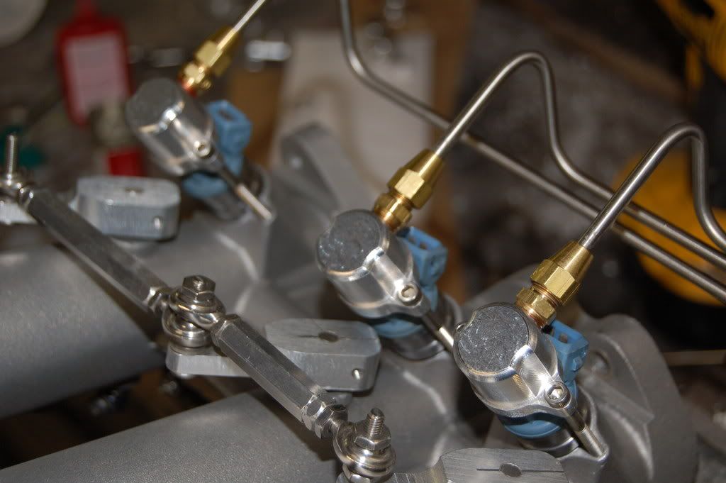
Maybe I can't see it well in the pics, but are'nt your lines directly in the way of your injector connectors?It's the angle of the dangle. The clips are tight but you can get them on and off without removing the line. And your right there's no turning the injector. Not only will it hit the linkage arm but it negates design criteria #1 "Looks Cool"
I'll make them available as soon as I get the manifold squared away. Although I did pressure test the clamp and injector at 125 psi with no leaks so I guess I got the bore size right!So... I was thinking about how neat its gonna be seeing it all with lines, and the vacuum fittings, and fully installed on the car, and stuff (sorry I am kinda getting obsessed here) and I started thinking, "hey, didn't we want some of those injector fuel plug/holddowns? What was the deal with those again?"Derek
-
This is going to be a reality very soon... I can't believe how excited I am getting!!
you *are* going to put a big horn or two on the exhaust, right?? not trumpet-style horn like the intakes, but more like old school, low-tech megaphone style.... I've never been fond of superTrapps, but the shape is about right.. and a pair of flared exits on slightly upward tilting, dual pipes (say, 2" apiece, you can flatten a couple sections for clearance to make the run back and across the car with 'em and they'll flow as well as a single 3"; just gotta make sure you have about a linear foot of "collector pipe" in the system then split it back into two pipes) just fit this intake....
After all, you are "that horny Z guy..."
Too late. 5" round magnaflow resonator and a Magnafow straight through oval as the muffler. Sounds sweet. And in a few weeks should sound even sweeter!
Derek
-
Well since Phar pointed out just how fugly the clamps were without the radius edge I had to add it to the final design.
And I'm glad I did! Thanks for the push, it definitely made a big difference in the look.
Check out that awesome chatter in the cuts. People pay big bucks for that you know.
I guess I'm going to have to splurge and get some decent mills.
Now on to the injector line looms.
Derek
-
Nissan, Too used the Goo.
Techline Coatings may have something in a 'sample' they could send your way. They have offices in Murietta CA (Temecula) and Texas as I recall.
They make rotor coatings that are semi-abradable for blower rotors. And they can be applied and cured fairly easily. That may work as well. But if you can get the same stuff the OEMs' use...
One Quart of the official goo will be arriving on Monday or Tuesday. Which is a good thing as it looks like I'll be starting the install on Monday or Tuesday!!
Busted butt and got far enough ahead of the foundry to get it started. I won't be able to stick with it exclusively so I'm figuring on a 2 week window.
Derek
-
Here's how I plan to do it.
5/16" hose from fuel tank drain plug conversion to lift pump. lift pump to surge tank. surge tank to high pressure pump. high pressure pump to 5/16 metal line passengers side. 1/4" return to surge tank. 3/16" line becomes atmospheric vent for tank. The vent to the filler neck is there for refueling only.You would need to T into that 3/4" line at the filler neck and run that either to the front of the car via the 3/16" line or vent it to the atmosphere in the rear of the car. Not a great idea as the fumes may find their way into the cabin. You should also add a rollover valve at the T. If you come up with on let me know as I haven't found one yet. If you don't T off of the filler neck and just use one of the extra fittings on the tank every time you fill up fuel will find it's way through the vent line. If it's in the 3/4" line at the neck it's mostly above the fuel level. This part I know from experience!
Derek
-
What's 0.125" divided by 6? Equivalent to about a 0.020" hole in each throttle plate. Assuming total circumfrential seal.
Now, take the diametrical distance to find circumfrence and divide that legnth into 0.020" and you start seeing where Accurate Injection gets his data about less than 0.002" being too much on a 45mm bore!
There is a BIG difference between breathing through ONE plate, and SIX!
I cracked my dual SU plates less than the 0.003 mentioned to get my idle speed correct. I could have drilled a hole in the throttle plates, but since I didn't have any spares and didn't want to JB Weld any mistakes I defaulted to throttle position instead of a hole. I figures something on the order of 1/16" in each of the two plates would be more than enough with throttle angle being used to 'trim up' to the final idle speed during synch.
But that's only two plates, not six!
The old cumulative error problem.
And that's my biggest fear. I'm going around and around on the goo. As Tony has said before there is a very real problem of build up of crud between the butterfly and bore. So much so that ford got a patent specifically for their goo. BMW uses it as well. Heck even Rochester used it on their tri-power setups. The DAG 213 is a dry lubricant that just so happens to provide a bit of sealing depending on how it's applied. Put it on a bore surface and install the butterfly and it's a lubricant. Paint it on a bore with the butterfly installed and it's a sealer and lubricant.
Here's my reasoning for buying the goo.
1) It's my daily driver and I want it to be dependable.
2) I'm hoping to sell a few of these and I want them to be the best quality.
3) In the time it will take me to pull the manifold and apply the DAG I can earn more than $95.00
4) I've spent many thousands in time (not hobby time but pattern making a living time) and materials on this rig so what's another $95.00
I'm ordering it today.
Derek
-
Derek, how long ago did you contact them about making their patterns for them? It would have to be more than a year ago, right?
Any word on the status of their product?
In April it will be just over 2 years. I'm not sure of the status of the manifold.
Derek
-
When I first started my lust for a unique intake for my car I figured a triple SU would be cool. I then learned the Z Therapy had already made one and had a video on you tube. I called out there and talked to them about making the patterns for them. They said that they had already secured a pattern maker to produce the patterns. That's when I started looking for something else to make and the rest is history... or at least in a few weeks it should be history. All and all I'm glad it turned out the way it did!
Derek


Injector wire gauge question
in Ignition and Electrical
Posted
I'm ordering up the wire for my manifold install. I'm using 4 conductor shielded wire. One positive and one negative for each bank. So each wire will be supplying 3 injectors. Is 18ga sufficient?
Thanks
Derek